

Protekdevices 587B051, 587B301, 587B201, 587B151 Datasheet
05016
587B051
thru
. . . engineered solutions for the transient environment™
120V AC POWER LINE SURGE SUPPRESSOR
APPLICATIONS
✔ Hard Wired Equipment AC Power Protection
✔ Load Side Distribution Systems
✔ Secondary Protection for Light Industrial AC Power
IEC COMPATIBILITY (EN61000-4)
✔ 61000-4-5 (Surge): 1kA, 8/20µs - Level 4(Line-Line) & 333A Level 4(Line-Ground)
FEATURES
✔ Meets ANSI/IEEE C62.41 Requirements
✔ Listed to CSA, File LR65240
✔ Differential and Common Mode Protection
✔ Low Clamping Voltage
✔ Nanosecond Response Time
✔ Long Life and Maintenance Free
MECHANICAL CHARACTERISTICS
✔ Plastic Package
✔ Weight 485 Grams (Approximate)
✔ Flammability Rating UL 94V-0
✔ Device Marking: Part Number , Logo, Voltage and Current Rating
DESCRIPTION
587B301
U.S PATENT 4,563,720
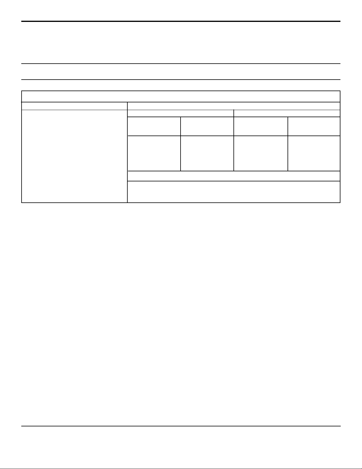
FIGURE 1
CONDITION
Time - µs
8
6
4
Kilovolts
2
0
TRANSIENT VOLTAGE THREAT
0 10 20 30 40 50 6 0
The 587B Series of 120 Volt AC Surge Suppressors is designed for use by the OEM,
equipment installer and or maintenance contractor. These modules employ a three
stage technology proven to be the most cost effective and reliable method in protecting
sensitive electronic equipment from over voltage transients.
This series is designed to protect AC powered equipment from the 6,000 Volt peak
open circuit voltage and 3,000 Amp short circuit current as defined in ANSI/IEEE
C62.41, Category CI.
The 587B Series offers a high degree of protection against 120 VAC line noise. It is
ideal for protecting 400 Volt components because the solid state TVS technology
assures that the line-to-neutral voltage will not exceed 400 Volts. While the modules
are designed for transient voltage protection, the advanced circuitry will also attenuate
the amplitude and slow the rate of rise of high frequency noise. The 587B Series
includes differential mode and common mode protection, which is effective in reducing
interference from line to equipment and are effective in reducing equipment generated
noise to meet FCC, VDE and CSA interference requirements.
05016.R3 11/02
1
TYPICAL CLAMPING ACTION
6
4
2
Kilovolts
0
0 10 20 30 4 0 50 60
Figures 1 and 2 are photographs of digitized waveforms
showing the typical clamping action of a 15 ampere module.
A 12 Ohm resistor is used to represent a 10 Amp equipment
load. The load is then subjected to the ANSI/IEEE C62.41
Category CI test conditions (6,000V/3,000A). These photographs contrast the effect on equipment with and without the
protector.
FIGURE 2
OF A 15 AMP MODULE
Time - µs
www.protekdevices.com
DEVICE CHARACTERISTICS
SPECIFICATIONS @ 25°C
MAXIMUM RATINGS
Operating Line Voltage:
Maximum Line Current:
(Line-to-Neutral Only)
Transient Voltage:
Transient Current:
Current Leakage:
Line-to-Neutral:
Neutral-to-Ground:
Storage & Operating
Temperature:
(Measured at center of
mounting surface)
130 VAC Max
587B051: 5A
587B151: 15A
587B201: 20A
587B301: 30A
6000V
peak
3000A
peak
@ 130 VAC
1.0mA
0.5mA
-40°C to 85°C
PROTECTION
MODE
DIFFERENTIAL
(Line-to-Neutral)
COMMON
(Neutral-to-Ground)
Frequency (MHz)
Common Mode Attenuation
Differential Mode Attenuation
587B051
587B301
RESPONSE TO TRANSIENT VOLTAGES
CLAMPING TEST CONDITION
MAXIMUM
CLAMPING
VOLTAGE
295V
350V
500V
650V
FILTER CHARACTERISTICS (Noise Attenuation dB)
OPEN CIRCUIT
0.15
0.5
10
25
30
55
VOLTAGE
@ 1.2/50 µs
1000V
6000V
1000V
6000V
1.0
5.0
35
55
55
55
SHORT CIRCUIT
10
30
50
40
50
45
CURRENT
@ 8/20 µs
thru
500A
3000A
500A
3000A
ARRESTER DEFINITIONS
Clamping Voltage: The clamping voltage of an arrester is the voltage that appears across its terminals during conduction of a transient current.
Standard Wave Form: The waveform of a surge current or voltage is designated by a combination of two numbers. The first number is for the time
of the wave front expressed in microseconds from zero to the peak of the wave. The second number is for the time of the wavetail also expressed in
microseconds from zero to the instant that the wavetail reaches one half of the crest or peak value. Example, 8/20 µs waveform.
Transient Current: The transient current of an arrestor is the peak surge current which flows through the arrester when voltage clamping occurs.
OPERATION
For maximum effectiveness, the protector should be installed directly after the AC line on/off switch and fuse. This will protect the electronics from
the AC line switch arcing and the severe transients caused by a fuse clearing.
Some heat is produced when operating at full current load, and heat sinking may be required to maintain case temperature below 85°C. The case
temperature is measured at the center of the mounting surface. The unit should not be mounted to a low combusting temperature material such as
wood.
High energy transients will cause a large circulating current in the AC input line (2,500A is possible). To prevent electromagnetic coupling, the AC line
on the input side of the protector must be dressed away from other wiring; magnetic shielding may be required. In addition, the electrical service must
be connected to a low impedance earth ground.
www.protekdevices.com205016.R3 11/02
 Loading...