

Protekdevices 485ELC Datasheet
05039
. . . engineered solutions for the transient environment™
HIGH SPEED ETHERNET DATA LINE PROTECTOR
APPLICATIONS
✔ Ether net - 10/100 Base T
✔ Catagory 5 Systems
✔ RS-485 Serial Communication Lines
✔ ISDN Equipment/Systems
✔ Video Transmission Systems
IEC COMPATIBILITY (EN61000-4)
✔ 61000-4-2 (ESD): Air - 15kV, Contact - 8kV
✔ 61000-4-4 (EFT): 40A - 5/50ns
✔ 61000-4-5 (Surge): 8/20µs - 95A, L4(Line-Gnd) & 48A, L4(Line-Line)
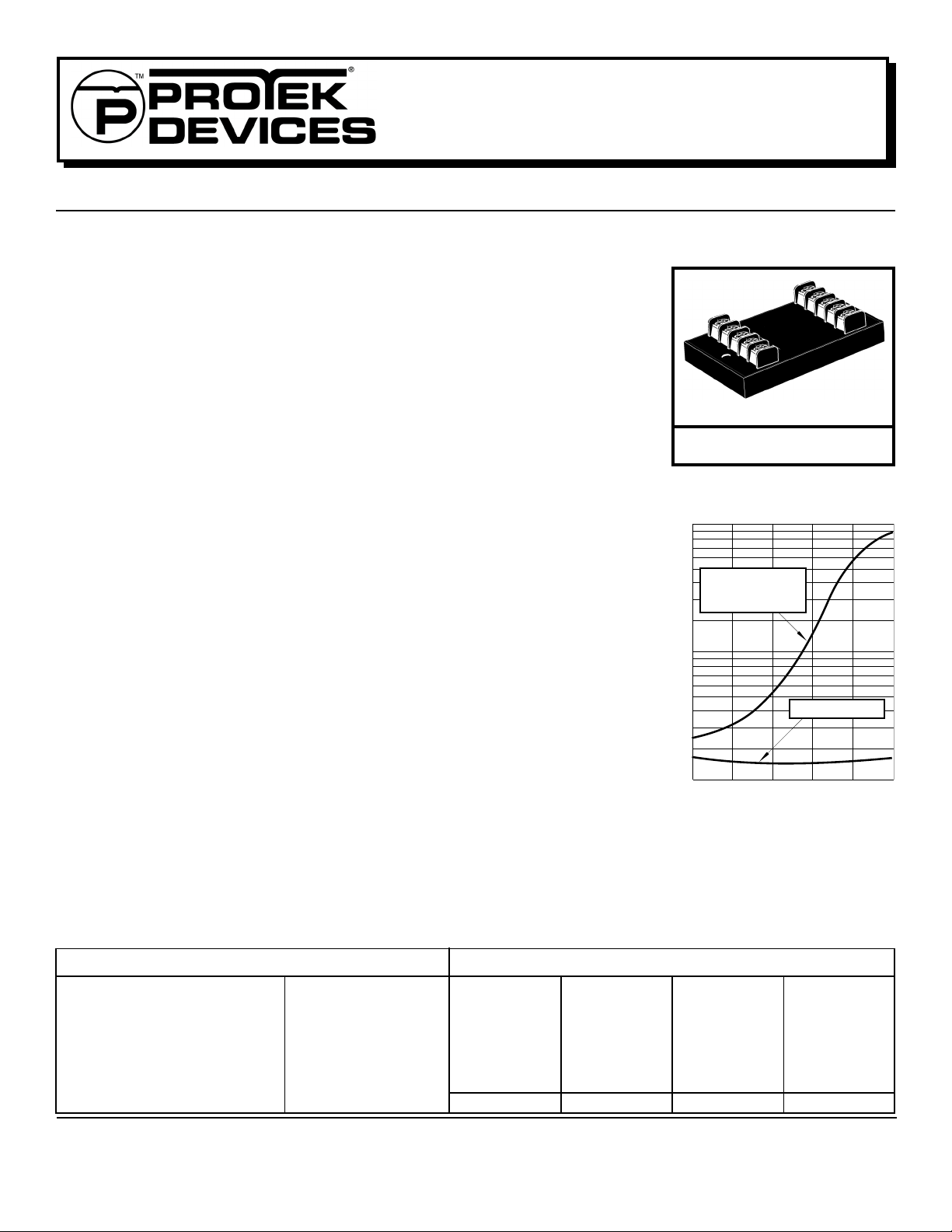
485ELC
485ELC
FEATURES
✔
Low Capacitance - 25pF
✔ Designed for EIA Standard RS-485 Data Lines
✔ Permanent Two-Stage 2 Line Pair Protection
✔ Subnanosecond Response Time
✔ Common & Differential Mode Protection
✔ Automatic Reset - Does Not Interupt Service
✔ Effective Against Lightning, Inductive Switching and ESD
MECHANICAL CHARACTERISTICS
✔ Weight: 485ELC - 142 grams(Approximate)
✔ Flammability Rating UL 94V-0
✔ Device Marking: Logo, Part Number & Terminal Designations
DESCRIPTION
The 485ELC is low capacitance, two-stage transient voltage protector the provides primary and
secondary protection against lightning, inductive switching and electrostatic discharge (ESD)
transient threats. The first stage diverts the transient current through the ground terminal return
path and the second stage clamps the voltage to a safe level without interuption of servic.
The 485ELC is designed to protect data lines, transmission lines, timing and control interface
circuits from common-mode (line-to-ground) or differential (line-line) transients. Terminals 1 & 2
and 3 & 4 are designed as line pairs. A transient voltage suppressor is connected across each
line pair for differential mode protection.
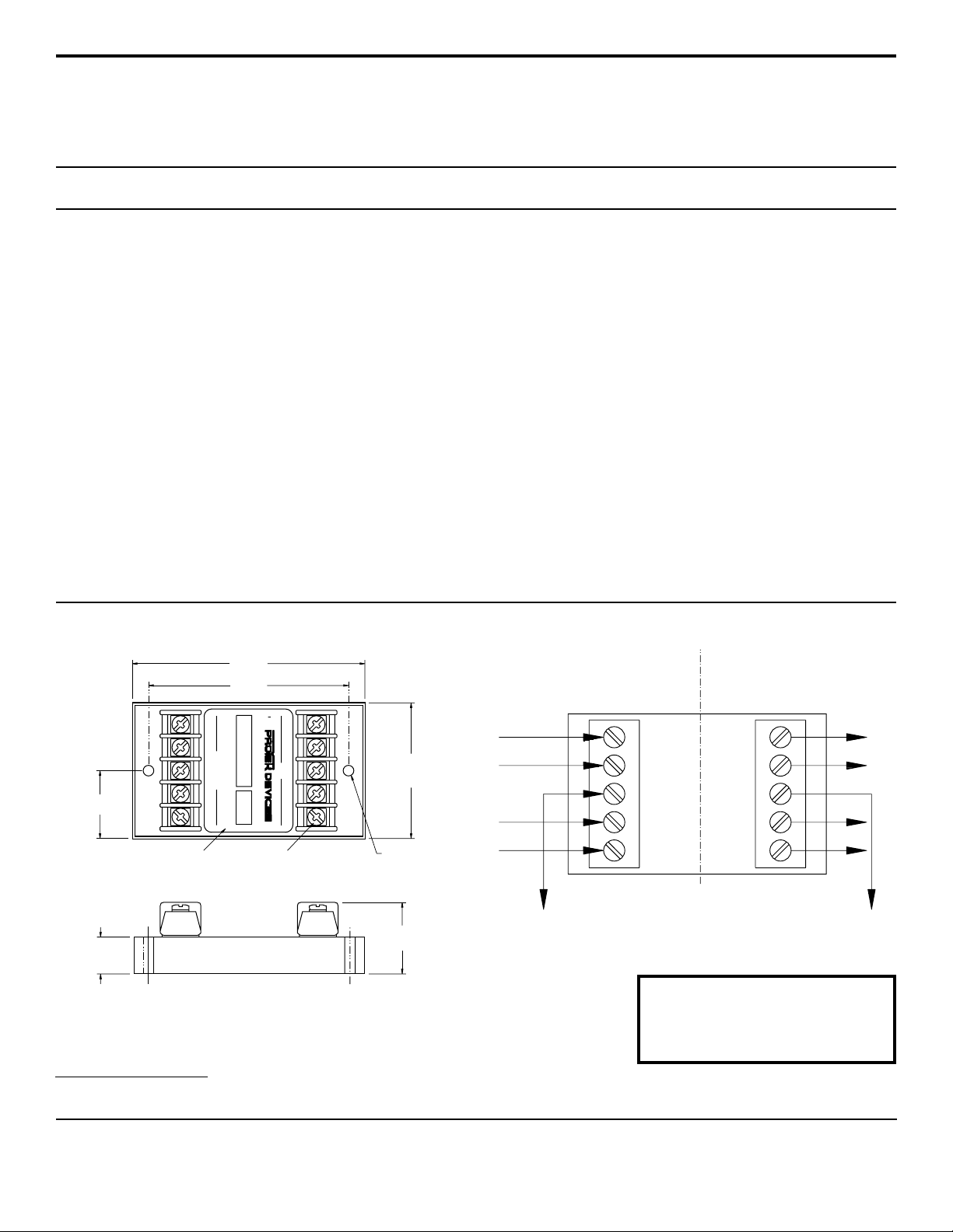
Capacitance over the operating voltage range is important. If capacitance is non-linear, distortion,
loss of data or access to the I/O port can occur (See Figure 1).
FIGURE 1
LINEAR CAP ACIT ANCE VS
1,000
100
C - Capacitance - pF
1,0
NON-LINEAR CAP ACIT ANCE
Industry Standard
Low Capacitance
Solid State Protector
ProT ek’s 485ELC
0 2 4 6 8 10
- Data Line Operating Voltage - Volts
V
OP
MAXIMUM RATINGS @ 25°C
Peak Operatiing Line Voltage (VOP)
Operating Line Current (IO)
Maximum Transient Voltage
Maximum Transient Current
(8/20µs waveform)
Operating & Storage Temperature
Response Time
±7V
250mA
20kV
10kA/Wire
40kA/Protector
-55°C to 100°C
< 1 nanosecond
ELECTRICAL CHARACTERISTICS @ 25°C
MAXIMUM
CLAMPING
VOLTAGE
MAXIMUM LINE
THRUPUT
RESISTANCE
(8/20µs)
@ 500A
V
C
VOLTS
R
OHMS
20 12 10 25
1 www.protekdevices.com05039.R2 4/02
MAXIMUM
LEAKAGE
CURRENT
@ 7V
OP
I
D
µA
MAXIMUM
CAPACITANCE
@ 0-7V, 1MHz
C
pF
INSTALLATION INSTRUCTIONS
485ELC
This product should be located as close as possible to the equipment
being protected. A low impedance grounding system is important to
maintain a low clamping voltage between the line-to-ground connection.
There are five (5) terminals on both the line and equipment side of the
485ELC - four data line terminals and two ground terminals. Both ground
terminals, as shown on the label, are connected internally. A single
ground connection is sufficient. However, it is recommended that both
ground connections be used for a lower impedance path to earth. This
connection can be made through the green AC power ground wire or a
known earth ground. The ground wire should be #14 stranded wire.
Incoming data lines are to cut or disconnected from the equipment to
insert the 485ELC product. The line side of the terminals are to be
connected to data lines from the outside world or lines that carry the
transient threats into the equipment to be protected. The equipment
side of the terminals are to be connected to the equipment to be
3.8” MAX
(95.5mm)
3.25”±0.015”
(82.6mm±0.38mm)
WARNING:
protected . The location of the product should be such that these wires
are as short as possible. A #18 or 20 gauge wire can be used for these
connections.
ProTek’s data line protector is designed with a short circuit failure mode
to give maximum protection. A fuse, fussable link, or circuit breaker is
recommended for each data/signal line on the input (line) side of the
protector for those applications that require an open circuit failure mode.
Caution: A low DC resistance ground may not be indicative of a good
lightning ground. Lightning contains a broad spectrum of frequencies up to 1 MHz. A low impedance path to ground at the transient frequencies is necessary. A ground strap is recommended or a #6 AWG
stranded wire. For wire lengths over 1.5 meters, there may be some
excessive line to earth potential under severe thunderstorm conditions.
For these applications, an additional protector may be necessary at the
equipment interface.
INST ALLA TION DIA GRAM485ELC Case Outline
Unprotected Side Protected Side
1
2
GND
3
4
1.125”
(30.2mm)
Adhesive Mylar Label
T erminal Strip
0.61” MAX
(15.5mm)
124 GND3
EQUIPMENT
#6 Screw
LINE
21 4GND 3
Te rminal Screw
2.25” MAX
(57.2mm)
Mounting
Hole for #8
Screw
1.19” MAX
(30.2mm)
1
2
GND
3
(Line Input Terminal)
Data Line From Outside World
Earth Ground Earth Ground
Note: Both ground terminals are common. Use second ground wire
to reduce impedance on long runs to earth ground connections
4
ProTek Devices
2929 South Fair Lane, Tempe, AZ 85282
Tel: 602-431-8101 Fax: 602-431-2288
E-Mail: sales@protekdevices.com
Web Site: www.protekdevices.com
COPYRIGHT © ProTek Devices 2001
SPECIFICATIONS: ProTek reserves the right to change the electrical and or mechanical characteristics described herein without notice (except JEDEC).
DESIGN CHANGES: ProTek reserves the right to discontinue product lines without notice, and that the final judgement concerning selection and specifications is the buyer’s and that in furnishing
engineering and technical assistance, ProTek assumes no responsibility with respect to the selection or specifications of such products.
05039.R2 4/02
2 www.protekdevices.com
(Equipment T erminal)
T o T ransmit/Receiv e Circuits
 Loading...