

Protekdevices 420LE60, 420LE35, 420LE28, 420LB60, 420LB35 Datasheet
...
05048
420LE28
thru
. . . engineered solutions for the transient environment
TWO LINE PAIR 4-20mA CONTROL LOOP PROTECTOR
APPLICATIONS
✔ Multi Process Control Loops
✔ Fire & Security Systems
✔ Petro-Chemical Plants
✔ Refineries & Tank Farms
IEC COMPATIBILITY (EN61000-4)
✔ 61000-4-2 (ESD): Air - 15kV, Contact - 8kV
✔ 61000-4-4 (EFT): 40A - 5/50ns
✔ 61000-4-5 (Surge): 8/20µs - 95A, Level 4(Line-Gnd) & 48A, Level 4(Line-Line)
FEATURES
✔ Designed for 4-20mA Current Loops
✔ Automatic Reset - Will Not Interrupt Service
✔ Permanent Two-Stage Line Pair Protection
✔ Line-to-Ground (Common) & Line-to-Line (Differential) Protection
✔ Subnanosecond Response Time
✔ Effective Against Lightning, Inductive Switching & ESD
420LB60
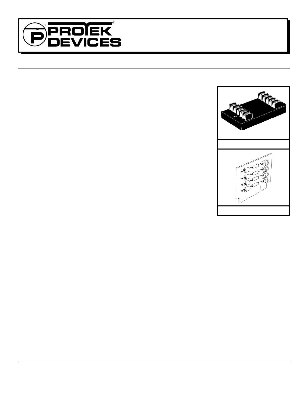
420LE PACKAGE
MECHANICAL CHARACTERISTICS
✔ Module Weight 160 grams (Approximate)
✔ Board Weight 32 grams (Approximate)
✔ Flammability Rating UL 94V-0
✔ Device Marking: Part Number, Logo, Date Code, and Ter minal Designations for the LE Device
420LB BOARD
DESCRIPTION
The 420LE/B series is a two stage transient voltage protector providing primary and secondary protection against lightning, inductive
switching and electrostatic discharge (ESD) transient threats. The first stage diverts the transient current through the ground terminal
return path and the second stage clamps the voltage to a safe level without interruption of service.
The 420LE/B series is designed to protect data lines from differential (line to line) and common mode (line to ground) transients.
Terminals 1 and 2, 3 and 4 for the 420LE and pins 2 and 3, 4, and 5 for the 420LB are designated as line pairs. Each line pair is
referenced to ground. A transient voltage suppressor is connected across each line pair for differential mode protection. Each line
pair is referenced to ground.
This product can also be used on telephone, signal/data lines, security, timing and control interface circuits. For most applications,
the product should be located as close as possible to the equipment being protected. A low impedance grounding system is important to maintain a low voltage clamp between the line-to-ground connection.
05048.R2 7/02
1
www.protekdevices.com
DEVICE CHARACTERISTICS
420LE28
thru
420LB60
MAXIMUM RA TINGS @ 250C
Operating Line Current 100mA
Operating Temperature -55 to 100
Storage Temperature -55 to 100
Transient Source Voltage 6kV
Transient Current (8/20µs) 10kA
ELECTRICAL CHARACTERISTICS @ 250C Ambient Temperature
MAXIMUM
OPERATING
0
PROTEK
C
0
C
PART
NUMBER
LINE VOLTAGE
V
OP
± VOLTS
420LE28
420LE35
420LE60
420LB28
420LB35
420LB60
28.0
35.0
60.0
28.0
35.0
60.0
MAXIMUM
LEAKAGE
CURRENT
@ V
OP
I
D
µA
5.0
5.0
5.0
5.0
5.0
5.0
MAXIMUM
CLAMPING
VOLTAGE
(8/20µs)
@2,000A
V
C
VOLTS
40
60
85
40
60
85
MAXIMUM
CAPACITANCE
@ 0 V, 1 MHz
C
pF
2800
1500
1000
2800
1500
1000
MAXIMUM
LINE THRUPUT
RESISTANCE
R
OHMS
12
12
12
12
12
12
INSTALLATION INSTRUCTIONS
There are five (5) terminals on the LINE SIDE and five (5) terminals on the EQUIPMENT SIDE of the 420LE, 4 data lines and one ground. Both
grounds are connected together internally. A single low impedance is ground sufficient. Incoming data lines are cut or disconnected from the
equipment to insert the 420LE/B products. The incoming lines are to be connected to the line side terminals as the equipment side lines are
connected to the equipment side terminals. The location of the product should be as close to the equipment as possible. The 420LE/B series is
designed with a short circuit failure mode to give maximum protection. A fuse, fussable link, or circuit breaker is recommended for each data/signal
line on the input side for those that require an open circuit failure mode.
Caution: A low DC resistance ground may not be a good ground. Lightning contains a broad spectrum of frequencies up to 1 MHz. A low
impedance path to ground at the transient frequencies is necessary. A ground strap is recommended or a #6 AWG stranded wire. For wire
lengths over 1.5 meters, there may be some excessive line to earth potential under severe thunderstorm conditions.
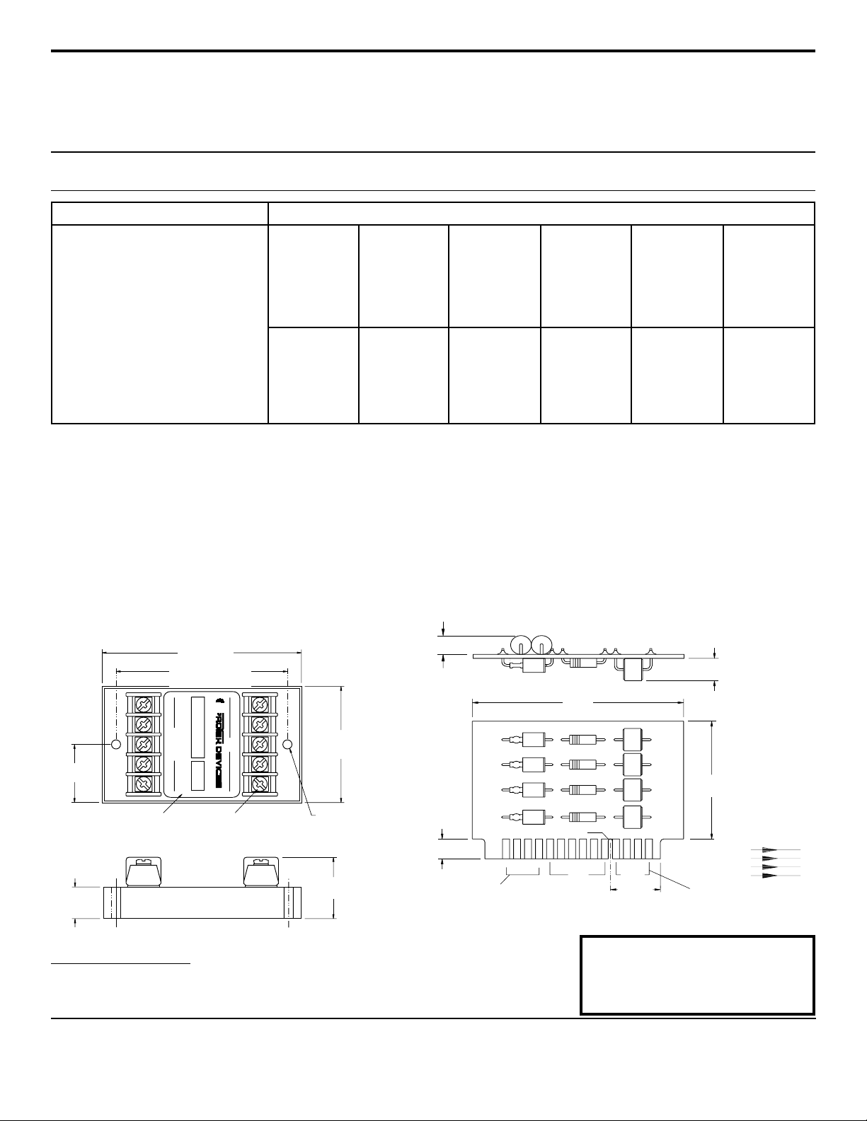
420LE CASE OUTLINE
420LB BOARD OUTLINE
3.8” MAX
(96.5mm)
3.25”±0.015”
(82.6mm±0.38mm)
WARNING:
EQUIPMENT
LINE
1.125”
(28.575mm)
Adhesive Mylar Label T ermi nal Screw
T erminal Strip
0.61” MAX
(15.5mm)
COPYRIGHT © ProTek Devices 2001
SPECIFICATIONS: ProTek reserv es the right to change the electrical and or mechanical characteristics described herein without notice (except
JEDEC).
DESIGN CHANGES: ProT ek reserves the right to discontinue product lines without notice, and that the final judgement concerning selection and
specifications is the buyer’s and that in furnishing engineering and technical assistance, ProT ek assumes no responsibility with respect to the
selection or specifications of such products.
124 GND3
#6 Screw
21 4GND 3
Mounting Hole for #8 Screw
2.25” MAX
(57.2mm)
1.19” MAX
(30.2mm)
0.325” MAX
(8.25mm)
EQUIPMENT
0.30” MAX
(7.6mm)
OUTPUT Connected to
Transmit/Receiver Circuits
NOTE: I/O contacts spaced at 0.156” (3.96 mm) centers
Orientation Notch
2
5
3.8” MAX
(95.5mm)
3.0” MAX
(76.2mm)
1.9” MAX
LINE
(48.2mm)
GND
12 15
0.07
(17.8mm)
INPUT Connected to Lines
From Out Side World
ProTek Devices
2929 South Fair Lane, Tempe, AZ 85282
Tel: 602-431-8101 Fax: 602-431-2288
E-Mail: sales@protekdevices.com
Web Site: www.protekdevices.com
www.protekdevices.com205048.R2 7/02
CONTINUITY
INPUT
12
13
14
15
OUTPUT
5
4
3
2
 Loading...