

Protekdevices 422E, 422B, 232E, 232B Datasheet
05060
232B
&
. . . engineered solutions for the transient environment™
INDUSTRIAL COMPUTER DATA LINE PROTECTOR
APPLICATIONS
✔ RS-232 Transmission Lines
✔ Catagory 3 Systems
✔ Control & Monitoring Systems
✔ Analog Signal Transmissions
✔ Telemetry Outstations
IEC COMPATIBILITY (EN61000-4)
✔ 61000-4-2 (ESD): Air - 15kV, Contact - 8kV
✔ 61000-4-4 (EFT): 40A - 5/50ns
✔ 61000-4-5 (Surge): 8/20µs - 95A, L4(Line-Gnd) & 48A, L4(Line-Line)
FEATURES
✔
4 Wire Line-Ground Protection
✔ Designed for EIA Standard RS-232 Data Lines
✔ Permanent Two-Stage Two (2) Line Pair or Four (4) Line Protection
✔ Subnanosecond Response Time
✔ Automatic Reset - Does Not Interupt Service
✔ Effective Against Lightning, Inductive Switching and ESD
232E
232B
232E
MECHANICAL CHARACTERISTICS
✔ Weight: 232E - 142 grams, 232B - 28 grams (Approximate)
✔ Flammability Rating UL 94V-0
✔ Device Marking: Logo, Part Number & Terminal Designations
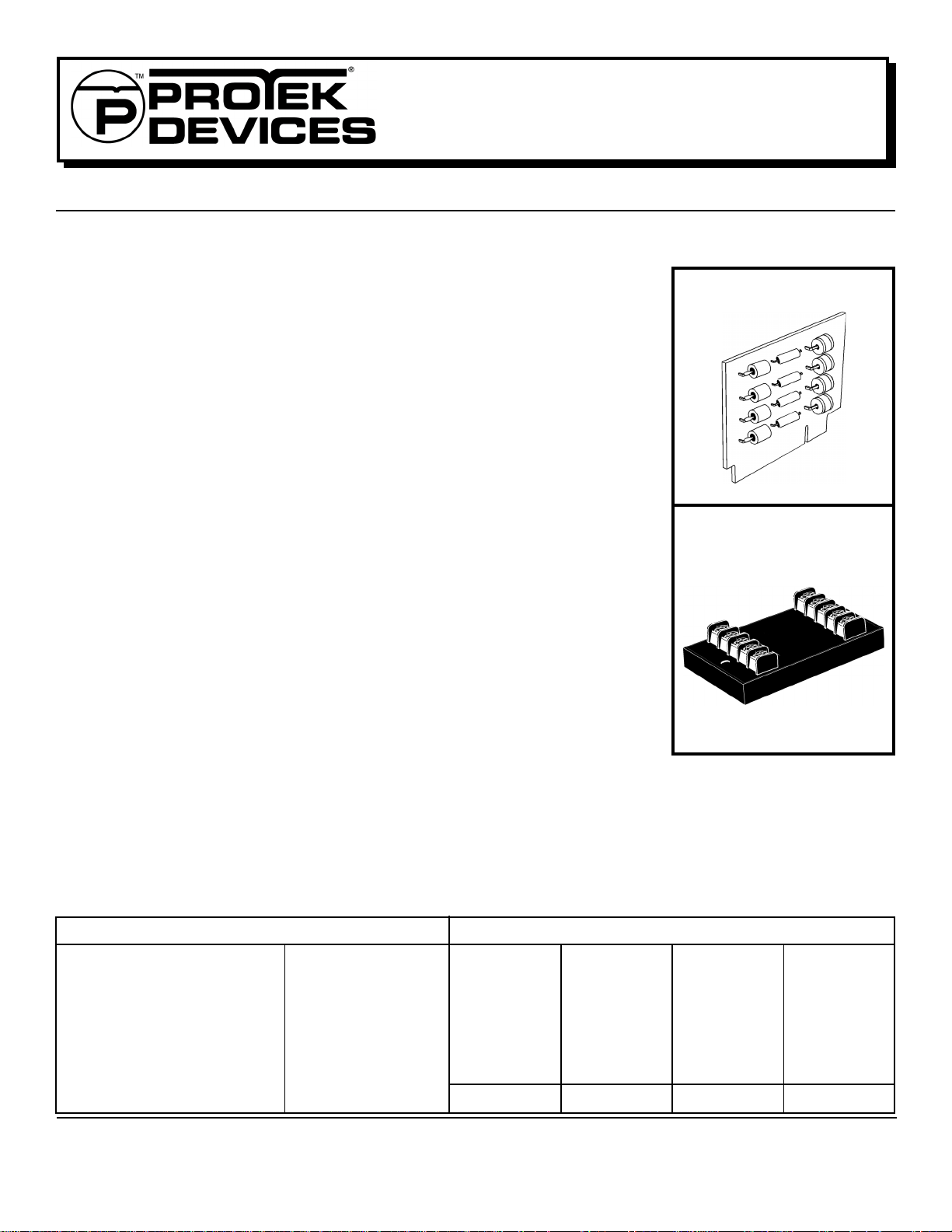
DESCRIPTION
The 232B/E is a two-stage transient voltage protector the provides primary and secondary protection against lightning, inductive switching and
electrostatic discharge (ESD) transient threats. The first stage diverts the transient current through the ground terminal return path and the second
stage clamps the voltage to a safe level without interuption of service.
The 232B/E is designed to protect two line pairs or four (4) data lines from common-mode (line-to-ground) lightning or switching transients. The
datalines are isolated to prevent near or far end cross talk problems. This product can also be used on data and transmission lines, security, timing
and control interface circuits.
MAXIMUM RATINGS @ 25°C
Peak Operatiing Line Voltage (VOP)
Operating Line Current (I
Maximum Transient Voltage
Maximum Transient Current
(8/20µs waveform)
Operating & Storage Temperature
Response Time
)
O
±25V
200mA
10kV
10kA/Wire
40kA/Protector
-55°C to 100°C
< 1 nanosecond
ELECTRICAL CHARACTERISTICS @ 25°C
MAXIMUM
CLAMPING
VOLT AGE
(8/20µs)
MAXIMUM
LINE
THRUPUT
RESISTANCE
@ 500A
V
C
VOLTS
R
OHMS
40 12 5 2000
MAXIMUM
LEAKAGE
CURRENT
@ 25V
OP
I
D
µA
MAXIMUM
CAPACITANCE
@ 0V, 1MHz
C
pF
1 www.protekdevices.com05027.R2 4/02
INSTALLATION INSTRUCTIONS
232B
&
232E
There are five (5) terminals on both the line and equipment side of the
232E - four data line terminals and two ground terminals. Both ground
terminals, as shown on the label, are connected internally. A single
The 232B circuit board requires an edge connector interface for
installation. The circuit board should be located at the building interface
for incoming lines from the outside world.
ground connection is sufficient. However, it is recommended that both
ground connections be used for a lower impedance path to earth. This
connection can be made through the green AC power ground wire or a
known earth ground. The ground wire should be #14 stranded wire.
Both the 232B and 232E can be mounted on a data line circuit panel
which must be hard wired to the incoming data lines. Unprotected input
lines and ground wires are to be separated from protected output lines to
prevent electromagnetic coupling of noise from high transient currents
Incoming data lines are to cut or disconnected from the equipment to
on the input lines.
insert the 232E product. The line side of the terminals are to be
connected to data lines from the outside world or lines that carry the
transient threats into the equipment to be protected. The equipment
side of the terminals are to be connected to the equipment to be
protected . The location of the product should be such that these wires
ProTek’s data line protector is designed with a short circuit failure mode
to give maximum protection. A fuse, fussable link, or circuit breaker is
recommended for each data/signal line on the input (line) side of the
protector for those applications that require an open circuit failure mode.
are as short as possible. A #18 or 20 gauge wire can be used for these
connections.
Caution: A low DC resistance ground may not be indicative of a good
lightning ground. Lightning contains a broad spectrum of frequencies Protectors should be installed at both ends of the data lines, at the point
of entry to buildings. Use the shortest possible connection to a low
impedance earth ground. Proper grounding and bonding are essential
for computer installation applications.
up to 1 MHz. A low impedance path to ground at the transient frequen-
cies is necessary. A ground strap is recommended or a #6 AWG
stranded wire. For wire lengths over 1.5 meters, there may be some
excessive line to earth potential under severe thunderstorm conditions.
For these applications, an additional protector may be necessary at the
equipment interface.
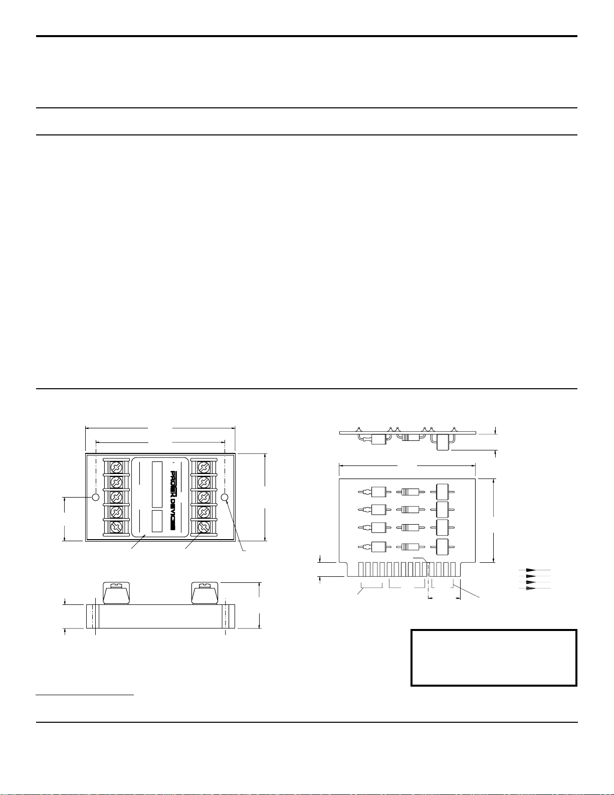
232B Board Outline
3.0” MAX
(76.2mm)
5
GND
12
(17.8mm)
ProTek Devices
2929 South Fair Lane, Tempe, AZ 85282
0.07”
0.50” MAX (12.7mm)
1.90” MAX
LINE
(48.2mm)
CONTINUITY
INPUT OUTPUT
12
15
INPUT Connected to Line From
Outside World
13
14
15
1.125”
(30.2mm)
Adhesive Mylar Label
T erminal Strip
0.61” MAX
(15.5mm)
232E Case Outline
3.8” MAX
(95.5mm)
3.25”±0.015”
(82.6mm±0.38mm)
WARNING:
EQUIPMENT
LINE
21 4GND 3
124 GND3
Te rminal Screw
#6 Screws
2.25” MAX
(57.2mm)
Mounting
Hole for #8
Screw
1.19” MAX
(30.2mm)
EQUIPMENT
030” MAX
(7.6mm)
OUTPUT Connected to
T ransmit/Receive Circuits
Note:
I/O contacts spaced at 0.156”
(3.96mm) centers.
Orientation Notch
2
Tel: 602-431-8101 Fax: 602-431-2288
E-Mail: sales@protekdevices.com
Web Site: www.protekdevices.com
COPYRIGHT © ProTek Devices 2001
SPECIFICATIONS: ProTek reserves the right to change the electrical and or mechanical characteristics described herein without notice (except JEDEC).
DESIGN CHANGES: ProTek reserves the right to discontinue product lines without notice, and that the final judgement concerning selection and specifications is the buyer’s and that in furnishing
engineering and technical assistance, ProTek assumes no responsibility with respect to the selection or specifications of such products.
5
4
3
2
05060.R2 4/02
2 www.protekdevices.com
 Loading...