

PROTEK TEL185E, TEL185B Datasheet
05050
TEL185B
&
. . . engineered solutions for the transient environment™
TELEPHONE INTERFACE PROTECTOR
APPLICATIONS
✔ Telecom Equipment Connected to Telcom Lines
✔ Line Connected Modems & Fax Machines
✔ Remote Telephone Extensions
✔ Private Wire/Leased Phone Lines
IEC COMPATIBILITY (EN61000-4)
✔ 61000-4-2 (ESD): Air - 15kV, Contact - 8kV
✔ 61000-4-4 (EFT): 40A - 5/50ns
✔ 61000-4-5 (Surge): 8/20µs - 95A, L5(Line-Gnd)
FEATURES
✔ Designed for ±185 Volt (Peak) Telephone Lines
✔ 4 Wire, Line-to-Ground Protection
✔ Permanent Two-Stage Protection
✔ Subnanosecond Response Time
✔ Automatic Reset - Does Not Interupt Service
✔ Effective Against Lightning, Inductive Switching and ESD
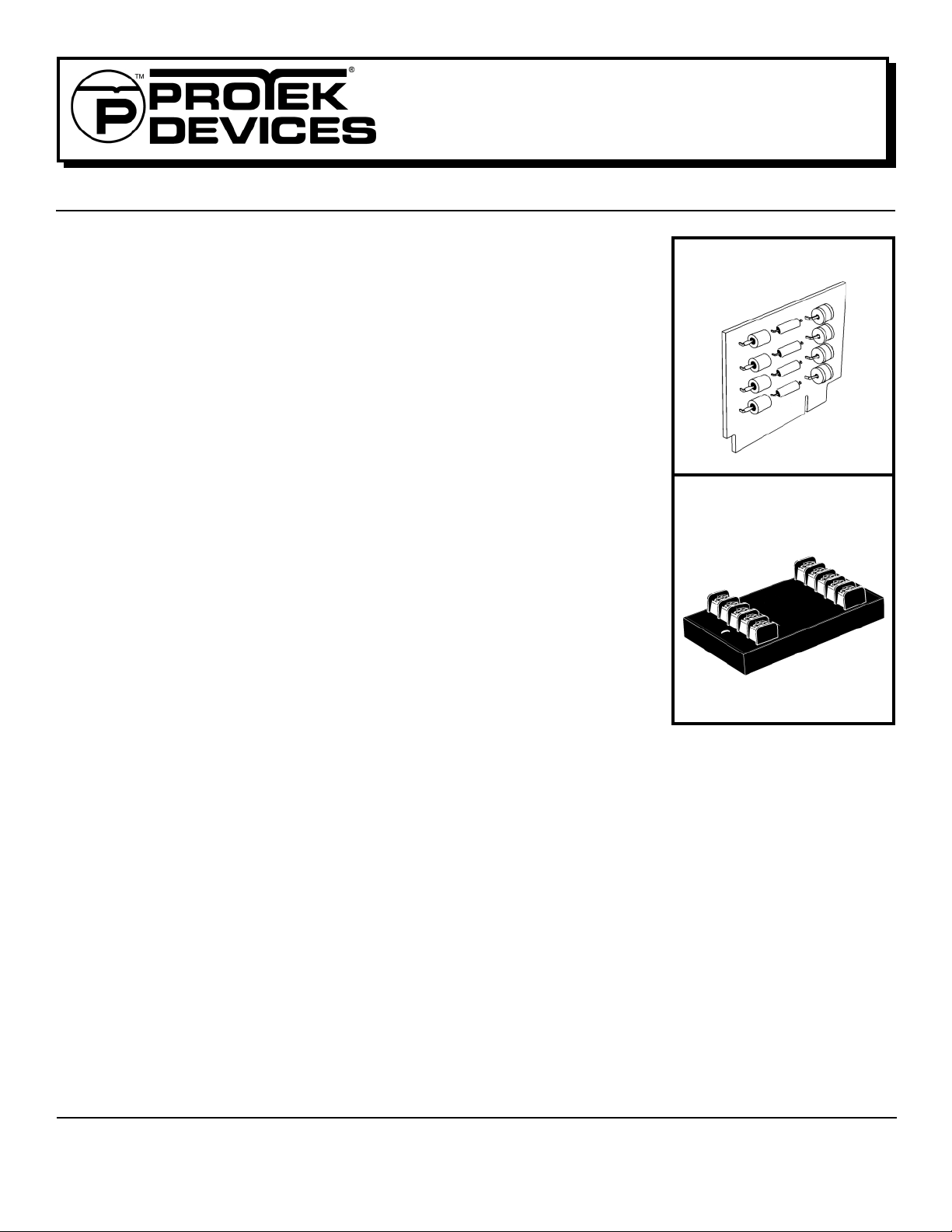
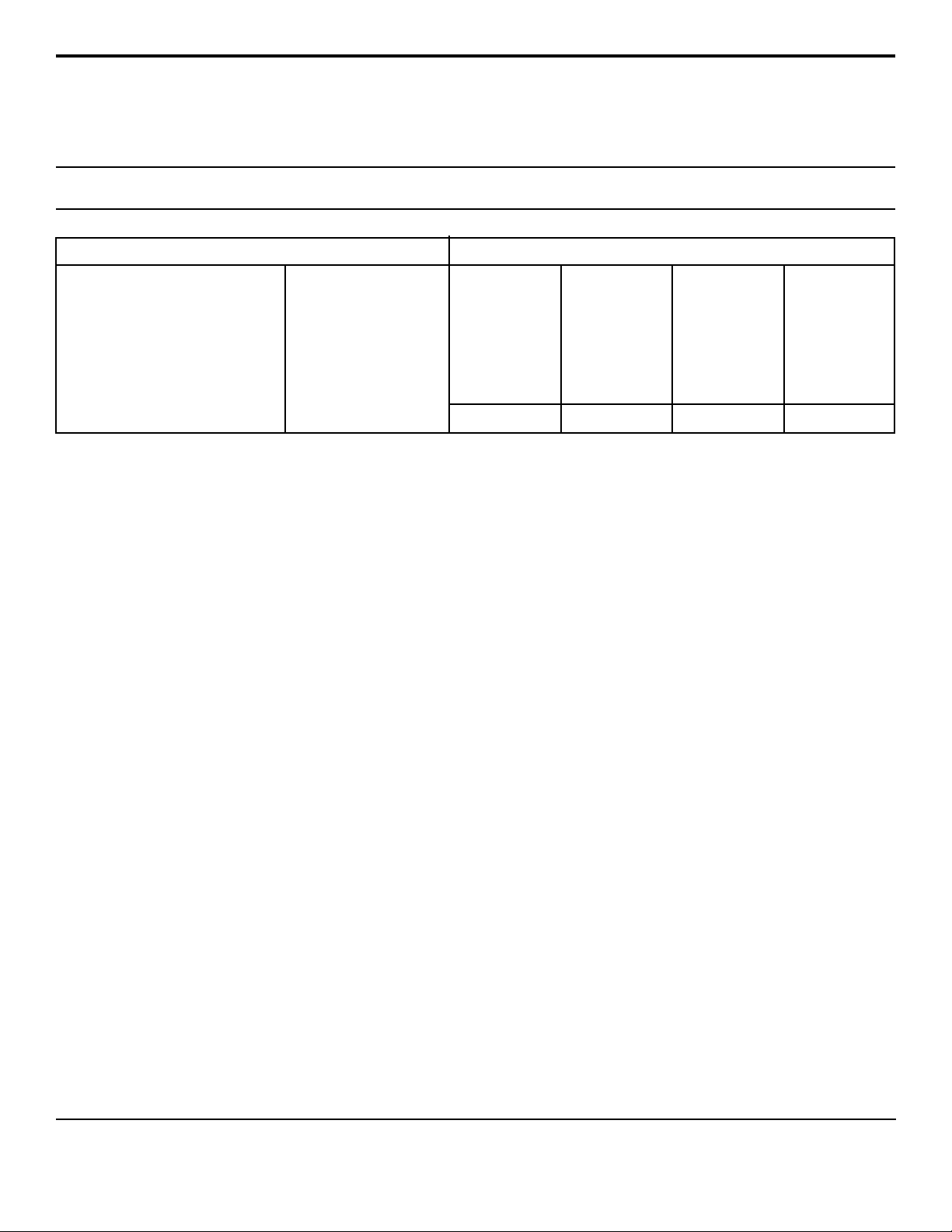
TEL185E
TEL185B
TEL185E
MECHANICAL CHARACTERISTICS
✔ Weight: TEL185E - 142 grams, TEL185B - 28 grams (Approximate)
✔ Flammability Rating UL 94V-0
✔ Device Marking: Logo, Part Number & Terminal Designations
DESCRIPTION
The TEL185B/E is a two-stage transient voltage protector the provides primary
and secondary protection against lightning, inductive switching and electrostatic discharge (ESD) transient threats. The first stage diverts the transient
current through the ground terminal return path and the second stage clamps
the voltage to a safe level without interuption of service.
The TEL185B/E is designed to protect telcom lines from common mode (line-toground) transients. There are four (4) independent lines referenced to the
ground terminals.
1 www.protekdevices.com05050.R2 1/03
DEVICE CHARACTERISTICS
TEL185B
&
TEL185E
MAXIMUM RATINGS @ 25°C
Peak Operatiing Line Voltage (VOP)
Operating Line Current (I
)
O
Maximum Transient Voltage
Maximum Transient Current
(8/20µs waveform)
Operating & Storage Temperature
Response Time
INSTALLATION INSTRUCTIONS
There are five (5) terminals on both the line and equipment side of the
TEL185E - four telcom line terminals and one ground terminal. The
ground terminal, as shown on the label, is connected internally. A single
ground connection is sufficient. However, it is recommended that both
ground connections be used for a lower impedance path to earth. This
connection can be made through the green AC power ground wire or a
known earth ground. The ground wire should be #14 stranded wire.
Incoming telcom lines are to cut or disconnected from the equipment to
insert the TEL185E product. The line side of the terminals are to be
connected to outside telephone or telecommunication lines that carry the
transient threats into the equipment to be protected. The equipment
side of the terminals are to be connected to the equipment to be
protected . The location of the product should be such that these wires
are as short as possible. A #18 or 20 gauge wire can be used for these
connections.
±185V
PEAK
200mA
20kV
10kA/Wire
40kA/Protector
-55°C to 100°C
< 1 nanosecond
ELECTRICAL CHARACTERISTICS @ 25°C
MAXIMUM
CLAMPING
VOLTAGE
(8/20µs)
MAXIMUM
LINE
THRUPUT
RESISTANCE
@ ±500A
V
C
VOLTS
R
OHMS
330 12 5 300
The TEL185B requires an edge connector interface for installation. A
standard 15 position edge connector can be use. When mounting or
wiring the connectors onto a printed circuit board, be sure that the
correct terminals are soldered. The line side of the board connections
are finger contacts 2 thru 5. The boards are conformal coated for limited
protection against moisture.
ProTek’s telcom line protector is designed with a short circuit failure
mode to give maximum protection. A fuse, PTC, fussable link, or circuit
breaker is recommended for each signal line on the input (line) side of
the protector for those applications that require an open circuit failure
mode.
Caution: A low DC resistance ground may not be indicative of a good
lightning ground. Lightning contains a broad spectrum of frequencies up to 1 MHz. A low impedance path to ground at the transient frequencies is necessary. A ground strap is recommended or a #6 AWG
stranded wire. For wire lengths over 1.5 meters, there may be some
excessive line to earth potential under severe thunderstorm conditions.
For these applications, an additional protector may be necessary at the
equipment interface.
MAXIMUM
LEAKAGE
CURRENT
@ ±185V
I
D
µA
MAXIMUM
CAPACITANCE
@ 0V, 1MHz
OP
C
pF
05050.R2 1/03
2 www.protekdevices.com
 Loading...