

PROTEK SMS12C, SMS15, SMS12, SMS15C, SMS05 Datasheet
...
SMS05
05132
Only One Name Means ProTek’Tion™
STANDARD CAPACITANCE TVS ARRAY
APPLICATIONS
✔ Ethernet - 10 Base T
✔ Cellular Phones
✔ Handheld Electronics
✔ FireWire & USB Interfaces
IEC COMPATIBILITY (EN61000-4)
✔ 61000-4-2 (ESD): Air - 15kV, Contact - 8kV
✔ 61000-4-4 (EFT): 40A - 5/50ns
✔ 61000-4-5 (Surge): 12A, 8/20µs - Level 1(Line-Gnd) & Level 2(Line-Line)
FEATURES
✔ 350 Watts Peak Pulse Power per Line (tp=8/20µs)
✔ Monolithic Design
✔ Available in Multiple Voltage Types Ranging From 5V to 24V
✔ Protect 4 Lines
✔ ESD Protection > 25 kilovolts
✔ Low Clamping Voltage
✔ Unidirectional & Bidirectional Configurations
✔ Low Leakage Current
thru
SMS24C
SOT-23-6
MECHANICAL CHARACTERISTICS
✔ Molded JEDEC SOT-23-6 Package
✔ Weight 0.6 grams (Approximate)
✔ Flammability rating UL 94V-0
✔ 8mm Tape and Reel Per EIA Standard 481
✔ Marking: Marking Code & Pin One Defined By DOT on Package
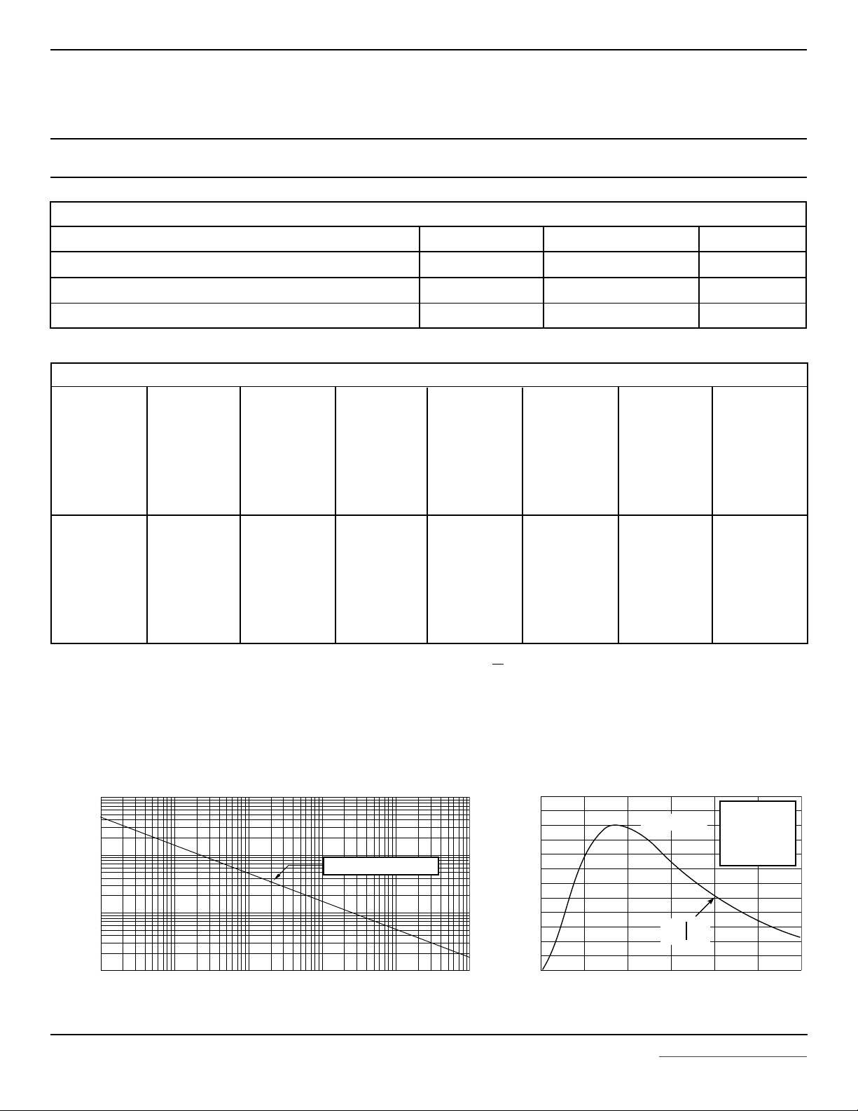
PIN CONFIGURATIONS
UNIDIRECTIONAL
1
2
3
6
5
4
BIDIRECTIONAL
1
2
3
6
5
4
105132.R3 9/03 www.protekdevices.com
DEVICE CHARACTERISTICS
MAXIMUM RATINGS @ 25°C Unless Otherwise Specified
SMS05
thru
SMS24C
PARAMETER
Peak Pulse Power (tp = 8/20µs) - See Figure 1
Operating Temperature
Storage Temperature
SYMBOL VALUE
P
PP
T
J
T
STG
350 Watts
-55°C to 150°C
-55°C to 150°C°C
ELECTRICAL CHARACTERISTICS PER LINE @ 25°C Unless Otherwise Specified
PA RT
NUMBER
(See Notes 1-3)
SMS05
SMS05C
SMS12
SMS12C
SMS15
SMS15C
SMS24
SMS24C
DEVICE
MARKING
PRH
PRL
PRI
PRM
PRJ
PRN
PRK
PRO
RATED
STAND-OFF
VOLTAGE
V
WM
VOLTS
5.0
5.0
12.0
12.0
15.0
15.0
24.0
24.0
MINIMUM
BREAKDOWN
VOLTAGE
@ 1mA
V
(BR)
VOLTS
6.0
6.0
13.3
13.3
16.7
16.7
26.7
26.7
MAXIMUM
CLAMPING
VOLTAGE
(See Fig. 2)
= 1A
@ I
P
V
C
VOLTS
9.8
9.8
19
19
24
24
40
40
MAXIMUM
CLAMPING
VOLTAGE
(See Fig. 2)
@8/20µs
VC @ I
PP
21.0V @ 17.0A
21.0V @ 17.0A
29.2V @ 12.0A
29.2V @ 12.0A
34.6V @ 10.0A
34.6V @ 10.0A
58.3V @ 6.0A
58.3V @ 6.0A
MAXIMUM
LEAKAGE
CURRENT
@V
I
D
µA
20
20
1
1
1
1
1
1
WM
UNITS
°C
TYPICAL
CAPACITANCE
(See Note 4)
@0V, 1 MHz
C
j
pF
150
150
80
80
50
50
40
40
Note 1: Part numbers with an additional “C” suffix are bidirectional devices, i.e., SMS05C.
Note 2:
Unidirectional Only:
Note 3:
Bidirectional Only:
Note 4:
Unidirectional Only:
10,000
1,000
100
- Peak Pulse Power - Watts
PP
P
10
0.1 1 10 100 1,000 10,000
Test between pin 1 to 2 or 5, 4 to 2 or 5, 6 to 2 or 5, 3 to 2 or 5.
Test between pin 5 to 1 or 3 or 4 or 6. Electrical characteristics apply in both directions.
Capacitance measured between pins 1, 3, 4, 6, to 2.
FIGURE 1
PEAK PULSE POWER VS PULSE TIME
350W 8/20µs Waveform
td - Pulse Duration - µs
2 www.protekdevices.com05132.R3 9/03
FIGURE 2
120
PP
100
80
60
40
- Peak Pulse Current - % of I
20
PP
I
0
0 5 10 15 20 25 30
PULSE WAVE FORM
t
f
Peak Value I
-t
e
td = t
t - Time - µs
PP
IPP/2
TEST
WAVEFORM
PARAMETERS
tf = 8µs
td = 20µs
 Loading...