

PROTEK SM8LC05, SM8LC08, SM8LC12, SM8LC15, SM8LC24 Datasheet
SM8LC05
05019
Only One Name Means ProTek’Tion™
LOW CAPACITANCE TVS ARRAY
APPLICATIONS
✔ Video On-Demand
✔ ISDN Telecom Interface
✔ USB, ADSL & SCSI Interfaces
✔ Modems
✔ LAN Interconnects
✔ Portable Electronics
IEC COMPATIBILITY (EN61000-4)
✔ 61000-4-2 (ESD): Air - 15kV, Contact - 8kV
✔ 61000-4-4 (EFT): 40A - 5/50ns
✔ 61000-4-5 (Surge): 24A, 8/20µs - Level 2(Line-Gnd) & Level 3(Line-Line)
FEATURES
✔ 800 Watts Peak Pulse Power per Line (tp=8/20µs)
✔ Bidirectional Configuration
✔ Available in 5 Voltage Types: 5V to 24V
✔ Protects Up to Two Line Pairs
✔ ESD Protection > 40 kilovolts
✔ ✔
✔
LOW CAPACITANCE: 25pF
✔ ✔
thru
SM8LC24
SO-8
MECHANICAL CHARACTERISTICS
✔ Molded JEDEC SO-8 Package
✔ Weight 15 milligrams (Approximate)
✔ Flammability rating UL 94V-0
✔ 12mm Tape and Reel Per EIA Standard 481
✔ Marking: Logo, Marking Code, Date Code & Pin One Defined By Dot on Top of Package
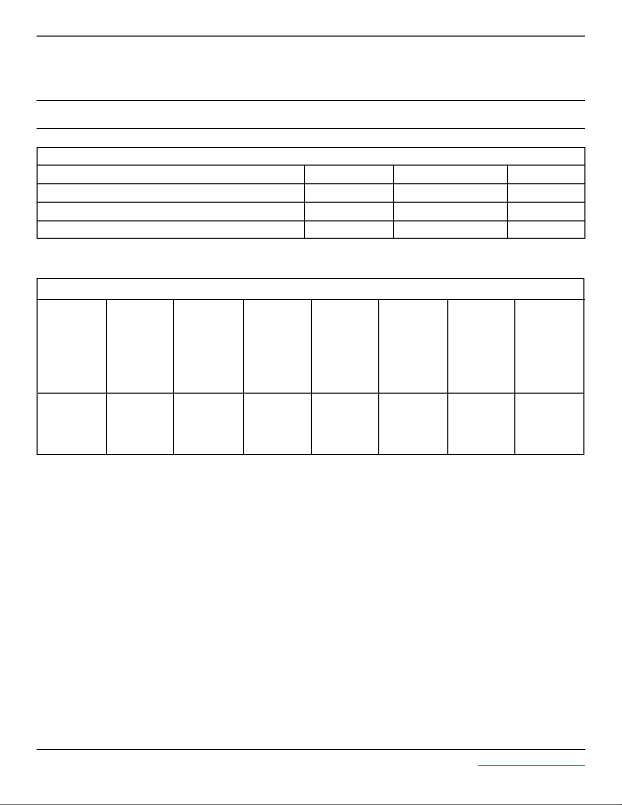
PIN CONFIGURATION
8
1
7
2
6
3
5
4
105019.R3 8/03 www.protekdevices.com
DEVICE CHARACTERISTICS
MAXIMUM RATINGS @ 25°C Unless Otherwise Specified
SM8LC05
thru
SM8LC24
PARAMETER
Peak Pulse Power (tp = 8/20µs) - See Figure 1
Operating Temperature
Storage Temperature
SYMBOL VALUE
P
PP
T
J
T
STG
800 Watts
-55°C to 150°C
-55°C to 150°C
UNITS
°C
°C
ELECTRICAL CHARACTERISTICS PER LINE @ 25°C Unless Otherwise Specified
PA RT
NUMBER
(See Note 1-2)
SM8LC05
SM8LC08
SM8LC12
SM8LC15
SM8LC24
Note 1: Devices are designed to be used in parallel (See Circuit Diagram) Page 1. For other applications, contact the factory. Do not surge in the
“forward” direction of the TVS.
Note 2: Do not surge from pins 1 to 8, 7 to 2, 6 to 3 and 4 to 5. PIV typically greater than 100 volts for each rectifier diode.
DEVICE
MARKING
PGA
PGB
PGC
PGD
PGE
RATED
STAND-OFF
VOLTAGE
V
WM
VOLTS
5.0
8.0
12.0
15.0
24.0
MINIMUM
BREAKDOWN
VOLTAGE
@ 1mA
V
(BR)
VOLTS
6.0
8.5
13.3
16.7
26.7
MAXIMUM
CLAMPING
VOLTAGE
(See Fig. 2)
@ IP = 1A
V
C
VOLTS
9.8
13.3
19.0
25.5
40.0
MAXIMUM
CLAMPING
VOLTAGE
(See Fig. 2)
@8/20µs
VC @ I
PP
24.6V @ 45A
25.5V @ 40A
32.9V @ 34A
38.5V @ 27A
48.5V @ 22A
MAXIMUM
LEAKAGE
CURRENT
@V
WM
I
D
µA
100
10
4
4
4
MAXIMUM
CAPACITANCE
0V @ 1 MHz
C
pF
25
25
25
25
25
2 www.protekdevices.com05019.R3 8/03
 Loading...