

SM20MT05C
thru
SM20MT24C
105079.R4 9/03 www.protekdevices.com
STANDARD CAPACITANCE TVS ARRAY
Only One Name Means ProTek’Tion™
APPLICATIONS
✔ Parallel Port
✔ RS-232, RS-422 & RS-423 Data Lines
✔ Industrial & Instrumentation Equipment
✔ Board Level Interface Protection
✔ I/O Port Protection
IEC COMPATIBILITY (EN61000-4)
✔ 61000-4-2 (ESD): Air - 15kV, Contact - 8kV
✔ 61000-4-4 (EFT): 40A - 5/50ns
✔ 61000-4-5 (Surge): 24A, 8/20µs - Level 2(Line-Gnd) & Level 3(Line-Line)
FEATURES
✔ 1500 Watts Peak Pulse Power per Line (tp=8/20µs)
✔ ESD Protection > 40 kilovolts
✔ Protection for 8 or 9 Bidirectional Data Lines
✔ Externally Low Clamping Voltage
✔ Available in 4 Voltage Types Ranging From 5V to 24V
✔ Bidirectional Configuration
✔ Monolithic Design
MECHANICAL CHARACTERISTICS
✔ Molded JEDEC SO-20WB (Wide Body) Package
✔ Weight 0.6 grams (Approximate)
✔ Flammability rating UL 94V-0
✔ 24mm Tape and Reel Per EIA Standard 481
✔ Marking: Logo, Part Number, Date Code & Pin One Defined By Dot on Top of Package
SO-20WB
(Wide Body)
05079
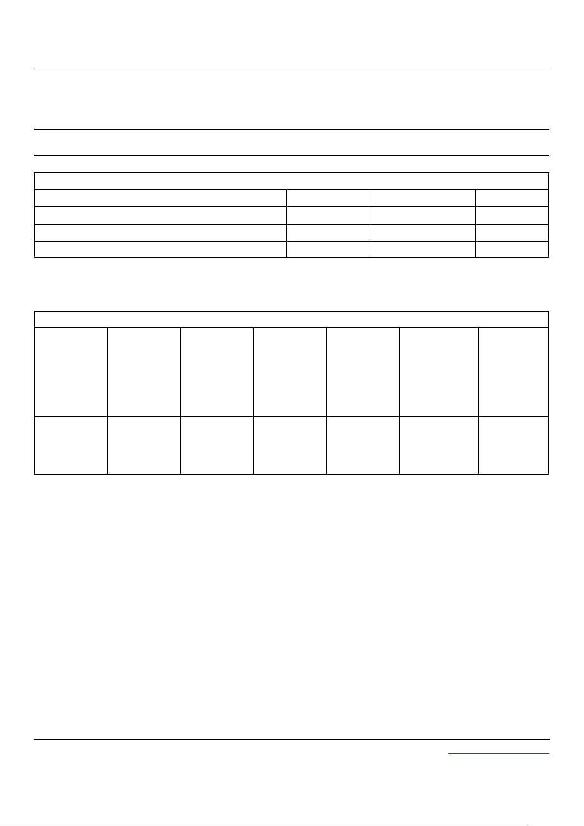
PIN CONFIGURATIONS
2
5
4
20
3
6
7
8
11
12
13
15
16
17
18
1
9
10
14
19
IN 1
IN 2
IN 3
IN 4
IN 5
GND
IN 6
IN 7
IN 8
I N 9
OUT 1
OUT 2
OUT 3
OUT 4
OUT5
GND
OUT 6
OUT 7
OUT 8
OUT 9
2
5
4
20
3
6
7
8
11
12
13
15
16
17
18
1
9
10
14
19
GND
IN 1
IN 2
IN 3
IN 4
IN 5
IN 6
IN 7
IN 8
GND
GND
OUT 1
OUT 2
OUT 3
OUT4
OUT 5
OUT 6
OUT 7
OUT 8
GND
EQUAL TO 8 BIDIRECTIONAL TVS DEVICES EQUAL TO 9 BIDIRECTIONAL TVS DEVICES
2 www.protekdevices.com05079.R4 9/03
SM20MT05C
thru
SM20MT24C
DEVICE CHARACTERISTICS
MAXIMUM RATINGS @ 25°C Unless Otherwise Specified
Operating Temperature
SYMBOL VALUE
-55°C to 150°C°C
°C
-55°C to 150°C
UNITS
T
J
T
STG
PARAMETER
Storage Temperature
Peak Pulse Power (tp = 8/20µs) - See Figure 1
P
PP
1500 Watts
ELECTRICAL CHARACTERISTICS PER LINE @ 25°C Unless Otherwise Specified
PA RT
NUMBER
(See Note 1)
RATED
STAND-OFF
VOLTAGE
V
WM
VOLTS
MINIMUM
BREAKDOWN
VOLTAGE
@ 1mA
V
(BR)
VOLTS
MAXIMUM
CLAMPING
VOLTAGE
(See Fig. 2)
@ I
PP
= 10A
V
C
VOLTS
SM20MT05C
SM20MT08C
SM20MT15C
SM20MT24C
5.0
8.0
15.0
24.0
6.5
10.0
18.0
25.0
9.5
13.0
23.0
31.0
11.0
12.0
26.0
36.0
MAXIMUM
LEAKAGE
CURRENT
@V
WM
I
D
µA
MAXIMUM
CAPACITANCE
@ 0V, 1 MHz
C
J
pF
50
10
4
4
700
360
250
140
Note 1: These devices are bidirectional only. Electrical characteristics apply in both directions. The monolithic TVS array is based on 10 unidirectional P/N junctions with a common cathode and can be configured to offer 8 to 9 bidirectional lines of protection. The inputs are symmetrical and can
be reversed for specific application layout requirements.
MAXIMUM
CLAMPING
VOLTAGE
(See Fig. 2)
@ 8/20µs
VC @ I
PP

3 www.protekdevices.com05079.R4 9/03
SM20MT05C
thru
SM20MT24C
GRAPHS
0 25 50 75 100 125 150
T
L
- Lead Temperature - °C
20
40
60
80
100
% Of Rated Power
Peak Pulse Power
8/20µs
Average Power
FIGURE 3
POWER DERATING CURVE
0
0 5 10 15 20 25 30
t - Time - µs
0
20
40
60
80
100
120
I
PP
- Peak Pulse Current - % of I
PP
TEST
WAVEFORM
PARAMETERS
tf = 8µs
td = 20µs
t
f
Peak Value I
PP
e
-t
td = t
IPP/2
FIGURE 2
PULSE WAVE FORM
0.1 1 10 100 1,000 10,000
td - Pulse Duration - µs
1,500W 8/20µs Waveform
100
1,000
10,000
100,000
P
PP
- Peak Pulse Power - Watts
FIGURE 1
PEAK PULSE POWER VS PULSE TIME

4 www.protekdevices.com05079.R4 9/03
SM20MT05C
thru
SM20MT24C
COPYRIGHT © ProTek Devices 2003
SPECIFICATIONS: ProTek reserves the right to change the electrical and or mechanical
characteristics described herein without notice (except JEDEC).
DESIGN CHANGES: ProTek reserves the right to discontinue product lines without notice, and that
the final judgement concerning selection and specifications is the buyer’s and that in furnishing
engineering and technical assistance, ProTek assumes no responsibility with respect to the
selection or specifications of such products.
PACKAGE OUTLINE & DIMENSIONS
ProTek Devices
2929 South Fair Lane, Tempe, AZ 85282
Tel: 602-431-8101 Fax: 602-431-2288
E-Mail: sales@protekdevices.com
Web Site: www.protekdevices.com
TAPE & REEL/BULK ORDERING NOMENCLATURE
1. Surface mount product is taped and reeled in accordance
with EIA-481.
2. Suffix-T13 = 13 Inch Reel - 1,000 pieces per 24mm tape,
i.e.,
SM20MT05C-T13.
3. No Suffix = Product Shipped in Tubes of 37 pcs per Tube.
Outline & Dimensions: Rev 1 - 11/01, 06018
A
B
C
D
F
G
J
K
P
R
12.95
7.60
2.65
0.49
0.90
1.27 BSC
0.32
0.25
10.55
0.75
0.499
0.292
0.093
0.014
0.020
0.05 BSC
0.010
0.004
0.395
0.010
0.510
0.299
0.104
0.019
0.035
0.05 BSC
0.012
0.009
0.415
0.029
12.65
7.40
2.35
0.35
0.50
1.27 BSC
0.25
0.10
10.05
0.25
DIM MIN MAX MIN MAX
MILLIMETERS
INCHES
PACKAGE DIMENSIONS
NOTES
1. - T - = Seating Plane and Datum Surface.
2. Dimensions “A” and “B” are Datum.
3. Dimensions “A” and “B” do not include mold protrusions.
4. Maximum mold protrusion is 0.015” (0.380 mm) per side.
5. Dimensioning and tolerances per ANSI Y14.5M, 1982.
6. Dimensions are exclusive of mold flash and metal burrs.
PACKAGE OUTLINE
SO-20WB
(Wide Body)
MOUNTING PAD
-A-
P
D
G
-T-
K
C
J
R X 45º
F
0.010” (0.25 MM)
M
B
M
10 PL
0.010” (0.25 MM)
S
B
M
20 PL
T
A
S
20 11
10
1
0.050” TYP
0.030” ± 0.005”
0.420” MIN
0.325” ± 0.005”
0.045” ± 0.005”
0º - 7º
-B-
 Loading...