

PROTEK PSD05C, PSD08, PSD08C, PSD03, PSD03C Datasheet
...
PSD03
1
2
05118
Only One Name Means ProTek’Tion™
STANDARD CAPACITANCE TVS ARRAY
APPLICATIONS
✔ Laptop Computers
✔ Cellular Phones
✔ Digital Cameras
✔ Personnal Digital Assistant (PDA)
IEC COMPATIBILITY (EN61000-4)
✔ 61000-4-2 (ESD): Air - 15kV, Contact - 8kV
✔ 61000-4-4 (EFT): 40A - 5/50ns
✔ 61000-4-5 (Surge): 24A, 8/20µs - Level 2(Line-Ground) & Level 3(Line-Line)
FEATURES
✔ Unidirectional: 500 Watts Peak Pulse Power per Line (tp = 8/20µs)
✔ BidirectionalL 400 Watts Peak Pulse Power per Line (tp = 8/20µs)
✔ Unidirectional & Bidirectional Configurations
✔ Replacement for MLV (0805)
✔ Protects One Power or I/O Port
✔ ESD Protection > 40 kilovolts
✔ Low Clamping Voltage
✔ Available in Multiple Voltage Types Ranging from 3V to 36V
thru
PSD36C
SOD-323
MECHANICAL CHARACTERISTICS
✔ Molded JEDEC SOD-323
✔ Weight 10 milligrams (Approximate)
✔ Flammability Rating UL 94V-0
✔ 8mm Tape and Reel Per EIA Standard 481
✔ Device Marking: Marking Code & Polarity Band
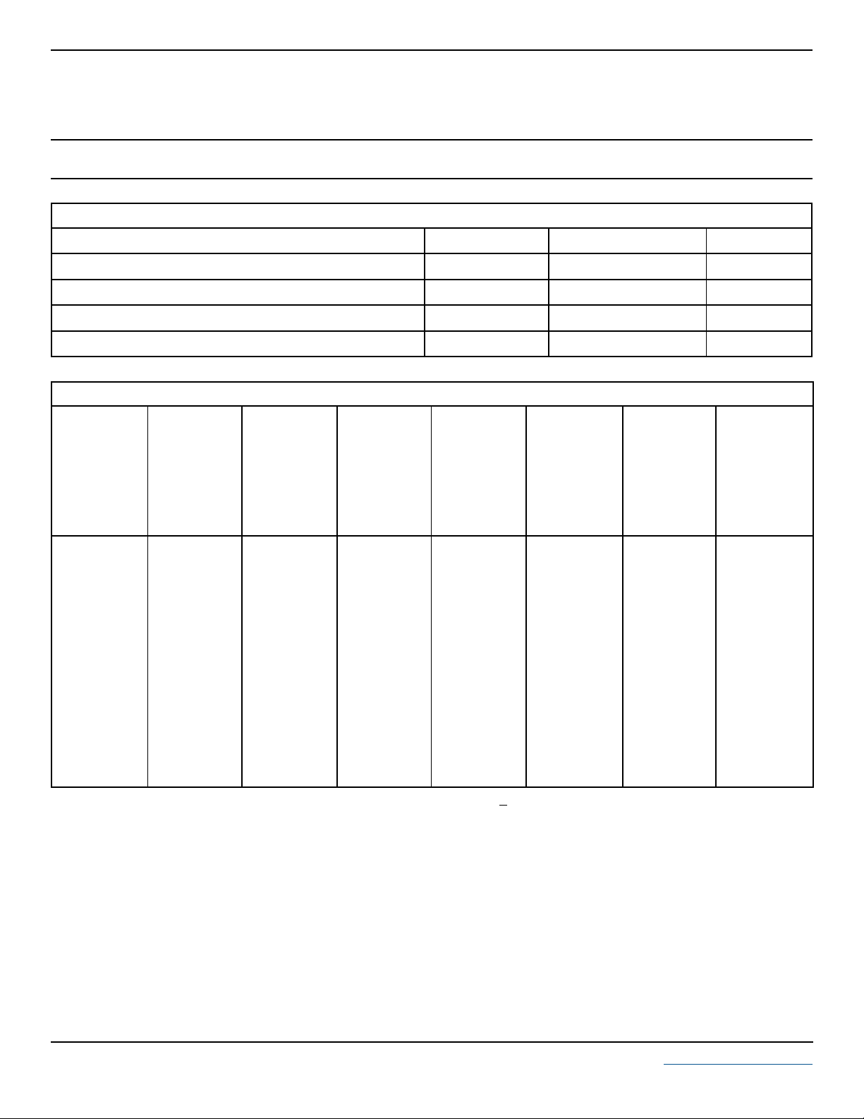
PIN CONFIGURATIONS
UNIDIRECTIONAL
(Unidirectional Only)
1
2
BIDIRECTIONAL
105118.R5 10/03 www.protekdevices.com
DEVICE CHARACTERISTICS
MAXIMUM RATINGS @ 25°C Unless Otherwise Specified
PSD03
thru
PSD36C
PARAMETER
Undirectional: Peak Pulse Power (tp = 8/20µs) - See Fig. 1
Bidirectional: Peak Pulse Power (tp = 8/20µs) - See Fig. 1 Watts400P
Operating Temperature
Storage Temperature
SYMBOL VALUE
P
PP
PP
T
J
T
STG
500
-55°C to 150°C
ELECTRICAL CHARACTERISTICS PER LINE @ 25°C Unless Otherwise Specified
PA RT
NUMBER
DEVICE
MARKING
(See Notes 1-2)
PSD03
PSD03C
PSD05
PSD05C
PSD08
PSD08C
PSD12
PSD12C
PSD15
PSD15C
PSD18
PSD18C
PSD24
PSD24C
PSD36
PSD36C
Note 1: Part numbers with an additional “C” suffix are bidirectional devices, i.e., PSD05C.
Note 2:
For Bidirectional Devices Only:
A
G
B
H
C
J
D
K
E
L
G
N
F
M
R
T
RATED
STAND-OFF
VOLTAGE
MINIMUM
BREAKDOWN
VOLTAGE
MAXIMUM
CLAMPING
VOLTAGE
(See Fig. 2)
= 1A
@ 1mA
V
WM
VOLTS
3.3
3.3
5.0
5.0
8.0
8.0
12.0
12.0
15.0
15.0
18.0
18.0
24.0
24.0
36.0
36.0
Electrical characteristics apply in both directions.
V
(BR)
VOLTS
4.0
4.0
6.0
6.0
8.5
8.5
13.3
13.3
16.7
16.7
20.0
20.0
26.7
26.7
40.0
40.0
@ I
P
V
VOLTS
6.5
7.0
9.8
9.8
13.4
13.4
19.0
19.0
24.0
24.0
29.0
29.0
43.0
43.0
60.0
60.0
C
MAXIMUM
CLAMPING
VOLTAGE
(See Fig. 2)
@8/20µs
VC @ I
PP
10.9V @ 43.0A
10.9V @ 39.0A
13.5V @ 42.0A
14.5V @ 28.0A
16.9V @ 34.0A
18.5V @ 17.0A
25.9V @ 21.0A
29.5V @ 14.0A
30.0V @ 17.0A
33.0V @ 12.0A
40.0V @ 9.0A
40.0V @ 9.0A
49.0V @ 12.0A
46.2V @ 9.0A
75.0V @ 5.0A
75.0V @ 5.0A
MAXIMUM
LEAKAGE
CURRENT
@V
I
D
µA
125
125
10
10
10
10
1
1
1
1
1
1
1
1
1
1
WM
UNITS
Watts
°C-55°C to 150°C
°C
TYPICAL
CAPACITANCE
@0V, 1 MHz
C
J
pF
500
200
350
175
250
150
150
50
100
40
90
40
88
40
75
35
2 www.protekdevices.com05118.R5 10/03
 Loading...