

PROTEK PMMAD1106, PMMAD1107, PMMAD1109, PMMAD130, PMMAD1103 Datasheet
...
®
®
. . . . . Engineered solutions for the transient environment
PMMADPMMAD
PMMAD
PMMADPMMAD
SERIESSERIES
SERIES
SERIESSERIES
STEERING DIODE (RAIL CLAMP) ARRAY
APPLICATIONS
● High Frequency Data Lines
● RS-232 & RS-422 Interface Networks
● 10 Base T Networks
● LAN/ WAN
● Computer I/O Ports
FEATURES
● IEC 1000-4-2, -4 & -5 Industry Requirements
● Designed for Rail Clamp Protection
● ESD Protection > 40 kilovolts
● Working Voltage > 50 Volts
● UL 94V-0 Flammability Classification
● Available in Standard SO-14 Surface Mount Package
IEC 1000-4 COMPATIBLE
SO-14 PACKAGE
RAIL CLAMP CIRCUIT
+
I/O
Port
GND or (-)
DESCRIPTION
This series is designed with discrete diodes for complete isolation. Each diode
can be individually tested according to the electrical characteristics. For transient
voltage protection, two diodes are configured in series with the anode of one
connect to the cathode of the other diode (See Rail Clamp Circuit).
MAXIMUM RATINGS @ 25°C Ambient Temperature (unless specified)
Continuous Power Dissipation
Operating & Storage Temperature
Continuous Forward Current
MECHANICAL CHARACTERISTICS
Package
Packaging
Approximate Weight
Device Markings
Miscellaneous
500mW
-65° to +150°C
400mA
Molded SO-14 Surface Mount Package
Tube or 16mm Tape per EIA 481
0.15 grams
Logo & Part Number
Pin No. 1 Indicated by Dot on Top of Package
SEE DIAGRAMS ON FOLLOWING PAGE.
FIGURE 1
PULSE WAVE FORM
t
f
PP
100
50
- Peak Pulse Current - % of I
PP
I
0
0 10 20 30
Peak Value I
-t
e
= t
t
d
t - Time - µs
PP
IPP/ 2
TEST
WAVEFORM
P ARAMETERS
= 8 µs
t
f
= 20µs
t
d
Tel 602-431-8101 • Fax 602-431-2288 • E-mail sales@protek-tvs.com • Web www.protek-tvs.com
2929 South Fair Lane • Tempe, Arizona 85282 • USA
19
ELECTRICAL CHARACTERISTICS @ 25° C Ambient Temperature
PROTEK
PART
NUMBER
REPETITIVE
PEAK REVERSE
VOLTAGE
REVERSE
LEAKAGE
CURRENT
MAXIMUM
FORWARD
VOLTAGE
FORWARD
PEAK PULSE
CURRENT
MAXIMUM
CAPACITANCE
(See Fig. 1)
@ 10 µA
V
PRP Min
VOLTS
See Note 1 50
Note 1: Device Types Include: PMMAD130, PMMAD1103, PMMAD1105, PMMAD1106, PMMAD1107 and PMMAD1109. Electrical characteristics applies to all device types.
@ 40 V
I
RM
µA
0.1 1.2 25
@ 100 mA
V
F
VOLTS
@ 8/20 µs
I
PP
AMPS
40
@ 4 V, 1 MHz
C
pF
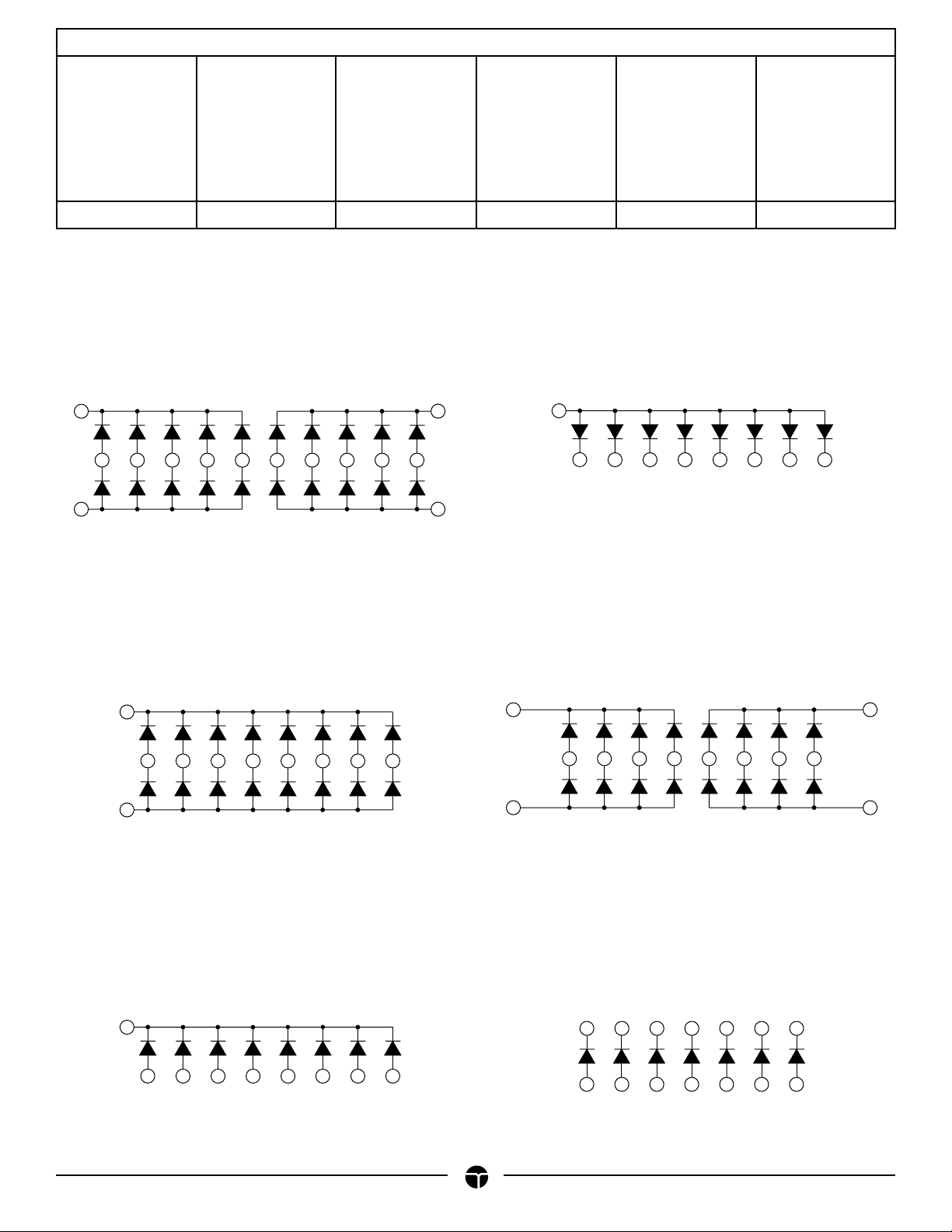
CIRCUIT DIAGRAM
PMMAD130
11
8
10 13 14 1 4 5 6 7
9
3
212
14
2
PMMAD1106
5 7 8 9 11 12
3
8 DIODE COMMON ANODE ARRAY
NC Pin 1, 4, 6, 10 & 13
DUAL 10 DIODE ARRAY
PMMAD1103
1
2
14
5 7 8 9 11 12
3
16 DIODE ARRAY
NC Pins 4, 6, 10 & 13
1
2
PMMAD1105
PMMAD1107
8
3 11 12 4 5 9 10
714
DUAL 8 DIODE ARRAY
NC Pins 6 & 13
PMMAD1109
20
14
2
5 7 8 9 11 12
3
8 DIODE COMMON CATHODE ARRAY
NC Pins 1, 4, 6, 10 & 13
8 5 4 3 2 1
7
8
9
11 12 13 14
10
7 ISOLATED DIODE ARRAY
(Independent)
®
5089 10/98
 Loading...