

Page 1

Page 2

PROTEK 9216A
Digital LCR Meter
User’s Manual
Volume 1: Basic Operation Rev. 3.0
Page 3

Table of contents
Introduction ........................................................................................................................................................... 4
Warranty......................................................................................................................................................... 4
General Safety Summary .............................................................................................................................. 5
Preventing Injury ..................................................................................................................................... 5
Preventing Instrument Damage .............................................................................................................. 5
Maintenance, Repair, and Storage ................................................................................................... 5
Product Damage Prevention ............................................................................................................ 6
Line Voltage Requirements .............................................................................................................. 6
Fuse Requirements .......................................................................................................................... 6
Conventions Used in This Manual ................................................................................................................. 7
Safety Terms ........................................................................................................................................... 7
Product Familiarization ......................................................................................................................................... 8
Front Panel Components ............................................................................................................................... 8
Fixture Inputs ........................................................................................................................................... 8
Measurement Modes and the Mode Selection Keys ............................................................................... 9
Alphanumeric Displays and Parameter Indicators .................................................................................. 9
Programming and Operator Interface Keys .......................................................................................... 10
Rear Panel Components .............................................................................................................................. 12
Specifications ............................................................................................................................................... 13
Display ................................................................................................................................................... 13
Test Conditions ...................................................................................................................................... 13
Accuracy ................................................................................................................................................ 13
Features and Options ................................................................................................................................... 14
General Features................................................................................................................................... 14
Options .................................................................................................................................................. 15
Basic Operations ................................................................................................................................................. 16
Operation of the LCR Meter For the First Time ........................................................................................... 16
Unpacking and Inspection ..................................................................................................................... 16
Installation ............................................................................................................................................. 16
Startup Procedures ...................................................................................................................................... 17
Before Applying Power .......................................................................................................................... 17
Before Using the Test Fixture................................................................................................................ 17
Fixture Options ............................................................................................................................... 17
Null Calibration Procedure .............................................................................................................. 18
Changing Test Setup Parameter Settings.................................................................................................... 18
2
Page 4

.
.
.
.
.
.
Default Setup ......................................................................................................................................... 19
Changing, Storing, and Recalling Custom Setups ................................................................................ 20
Measurement Mode........................................................................................................................ 20
Frequency ....................................................................................................................................... 20
Drive Voltage .................................................................................................................................. 21
Bias ................................................................................................................................................. 22
Measurement Rate ......................................................................................................................... 24
Settling Time .................................................................................................................................. 25
Triggering........................................................................................................................................ 25
Store and Recall ............................................................................................................................. 26
Range ............................................................................................................................................. 26
Series and Parallel Equivalent Circuits .......................................................................................... 29
Display Types ................................................................................................................................. 29
3
Page 5

Chapter
Introduction
Important Background Information
The PROTEK 9216A DIGITAL LCR Meter is a high quality instrument that gives you
many years of good service. Please read the information in this chapter before using or
applying power to the meter. Information on operating and using the meter is given in
the following chapters.
Warranty
PROTEK warrants that this product will be free from defects in materials and
workmanship for a period of one year from the date of purchase. If any such product
proves defective during this warranty period, PROTEK, at its option, either will repair the
defective product without charge for parts and labor, or will provide a replacement in
exchange for the defective product.
In order to obtain service under this warranty, the customer must notify PROTEK of
the defect before the expiration of the warranty period and make suitable arrangements
for the performance of service. The customer shall be responsible for packaging and
shipping the defective product to the service center designated by PROTEK, with
shipping charges prepaid. PROTEK shall pay for the return of the product to customer if
the shipment is to a location within the country in which the PROTEK service center is
located. The customer shall be responsible or paying all shipping charges, duties, taxes,
and any other charges for products returned to any other locations.
This warranty shall not apply to any defect, failure or damage caused by improper
use or improper or inadequate maintenance and care. PROTEK shall not be obligated
to furnish service under this warranty:
To repair damage resulting from attempts by personnel other than PROTEK repre-
sentatives to install, repair or service the product;
To repair damage resulting from improper use or connection to incompatible
equipment; or
To service a product that has been modified or integrated with other products when
the effect of such modification or integration increases the time or difficulty of
servicing the product.
This warranty is given by PROTEK with respect to this product in lieu of any other
warranties, expressed or implied. PROTEK and its vendors disclaim any implied
warranties of merchantability or fitness for a particular purpose.
4
Page 6

.
.
.
.
.
.
PROTEK’s responsibility to repair or replace defective products is the sole and
exclusive remedy provided to the customer for breach of this warranty. PROTEK
and its vendors will not be liable for any indirect, special, incidental, or
consequential damages irrespective of whether PROTEK or the vendor has
advance notice of the possibility of such damages.
General Safety Summary
Review the following safety precautions to avoid injury and prevent damage to this
product or any products connected to it.
NOTE: Only qualified personnel should perform service procedures.
Preventing Injury
Use Proper Power Cord. To avoid fire hazard, use only the power cord specified for this
product.
Avoid Electrical Overload. To avoid electric shock or fire hazard, do not apply a voltage
to a terminal this is outside the range specified for that terminal.
Ground the Product. This product is grounded through the grounding conductor of the
power cord. To avoid electric shock, the grounding conductor must be connected to
earth ground. Before making connections to the input or output terminal of the product,
ensure that the product is properly grounded.
Do Not Operate Without Cover. To avoid electric shock or fire hazard, do not operate
this product with covers or panels removed.
Use Proper Fuse. To avoid fire hazard, use only the fuse type and rating specified for
this product.
Do Not Operate in Wet/Damp Conditions. To avoid electric shock, do not operate this
product in damp or wet conditions.
Do Not Operate in an explosive atmosphere. To avoid injury or fire hazard, do not
operate this product in an explosive atmosphere.
Keep Probe Surface clean. To avoid electric shock and erroneous readings, keep the
probe surface clean.
Preventing Instrument Damage
Maintenance, Repair, and Storage
This equipment is composed of many high-precision components and components
which require high internal pressure. Care is required when handling or storing this
equipment.
Occasionally, if the surface of the panel is dirty, rub the affected area lightly with a
soft cloth soaked in a light neutral detergent or alcohol. Never use highly volatile
material such as benzene or paint thinner.
The ideal ambient temperature range for storing this equipment is 10C to 60C
(14F to 140F).
5
Page 7

To avoid personal injury, do not remove the product covers. Do not operate the
Rating
Operating Voltage Range
AC 115 V
AC 98 V–132 V
AC 230 V
AC 196–253 V
product without the covers properly installed.
Two spare fuses are shipped with this equipment.
In order to maintain this equipment in a stable and efficient operating condition,
calibrate the equipment after every 1,000 hours operating time or every 6 months,
whichever is shorter.
Product Damage Prevention
Use Proper Power Source. Do not operate this product from a power source that
applies more than the voltage specified.
Provide Proper Ventilation. To prevent product overheating, provide proper ventilation.
Do Not Operate With Suspected Failures. If you suspect there is damage to this
product, have it Suspected Failures inspected by qualified service personnel.
Do not immerse in Liquids Clean the probe using only a damp cloth. Refer to the
cleaning instructions.
Line Voltage Requirements
Refer to the following table for the correct operating voltage ranges for this LCR meter.
Check the line voltage prior to connecting to the power source, and verify that it is within
a voltage range listed below.
If the LCR meter is to be used at a voltage other than 230V AC, the operating voltage
may be changed by the following procedure ·
Remove the power cable from AC input.
Insert a flat-bladed screwdriver into the slot located on right side of the fuse holder
cap; remove the cap by pressing and then pulling up the screwdriver.
Rotate the cap on the fuse holder to set the voltage to the desired level.
Connect power cable to the AC input.
If a voltage below AC 115 V is required, the power cable and fuse may need to be
changed. In such case, contract your nearest dealer for appropriate service.
After use, disconnect the equipment from the AC outlet.
Fuse Requirements
In order to prevent circuit damage resulting from over current, use the correct fuse value.
The fuse ratings are as follows.
6
Page 8

.
.
.
.
.
.
Circuit No.
Shape (diameter length) mm
Rating
Remarks
F1101
5.2 20
250 V T500 mA
For AC l15V
250 V T250 mA
For AC 230 V
F601
5.2 20
250 V F250 mA
Circuit No.
Shape (diameter length) mm
Rating
Remarks
F602
5.2 20
250 V F250 mA
The internal fuse rating is as follows:
Note: Refer to the section on troubleshooting in the Reference Manual for instructions
on replacement of the internal fuse.
Conventions Used in This Manual
In this manual, you will find various procedures, which contain steps of instructions
for you to perform. To keep these instructions clear and consistent, this manual
uses the following conventions:
Operating procedures and names of front panel controls are in uppercase and
The case of each name used in the manual is the same (Initial Capitals or
Instruction steps are numbered (1, 2, 3, ), unless there is only one step.
When steps require that you make a sequence of selections using front panel
Safety Terms
The following terms are also used in this manual:
WARNING identifies conditions or practices that could result in injury.
CAUTION identifies conditions or practices that could result in damage to this
NOTICE identifies conditions or practices that could result in incorrect test
boldface print.
UPPERCASE) as that used on the instrument itself.
controls and keys, an arrow () is used in the text to indicate an LED result when a
front panel entry is made. Also, whether a name is a key or LED display reading is
clearly indicated:
Example: Press DISP (Entry) ENTER
product or other property.
data.
7
Page 9

Product Familiarization
Test Frequency
Measurement Rate
Bias
Test Voltage
Display option
Back space
Measurement modeFixture inputs
Trigger
Setup Key pad Enter
Chapter
2
Description of the LCR Meter and Its Features
In this chapter, the controls and connections of the LCR Meter are described, and its
basic operation is summarized in terms of the meter’s specifications, features and options,
and operating modes.
Front Panel Components
The front panel and its displays, controls, and connections are shown in the following
illustration:
First, the displays, controls, and connections on the left side of the front panel are explained, and then the many buttons and keys on the right side are described.
Fixture Inputs
The input terminals labeled IL, PL, PH, and IH connect the test fixture or adapter to the
instrument, as discussed in the section in Chapter 3 on “Connecting a Component.” Two
of the terminals provide a current source to the component under test, and the other two
terminals provide a high impedance connection to measure the voltage across the device.
This four-wire or “Kelvin” type of measurement setup is designed to increase accuracy by
reducing the amount of current in the voltage-sensing wires. Warning: Do not connect
any active voltage source to these terminals, especially high voltages.
Measurement Modes and the Mode Selection Keys
These keys select the measurement to make on the component under test. One of five
measurement modes may be selected: Auto, R+Q, L+Q, C+D or C+R. The selected
8
Page 10

mode is indicated by LEDs above the alphanumeric displays. The operation of each
1
mode can be explained as follows:
AUTO In this mode, the meter automatically selects the most appropriate
measurement on the device. The selection is made according to the following
criteria:
If |Q| < 0.125, the meter selects the R+Q measurement mode.
If Q > +0.125, the meter selects the L+Q measurement mode.
If Q < 0.125 and the meter is in the series equivalent circuit mode, the C+R
measurement mode is selected.
If Q < 0.125 and the meter is in the parallel equivalent circuit mode, the C+D
measurement mode is selected.
R+Q In this mode, resistance is displayed on the main parameter display
and the Q (quality factor) is displayed on the secondary parameter display. The R-
value is either the series or parallel equivalent resistance of the component under test.
The unit for R is , k, or M. The Q value is the dimensionless ratio of the
imaginary part of the component’s impedance to its real part. If Q has a positive (+)
value, the reactive component of the device under test is inductive. If Q has a
negative () value, it is capacitive.
L+Q In this mode, the series or parallel equivalent inductance value of a
component under test is displayed on the main parameter display units in units of µH,
mH, or H, and its dimensionless Q value is displayed on the secondary parameter
display.
C+D In this mode, the series or parallel equivalent capacitance value of a
component under test is displayed on the main parameter display in units of pF, nF,
or µF. On the secondary parameter display, the dimensionless ratio D 1/Q is given.
D is normally a small value for a good capacitor.
C+R In this mode, the capacitance is displayed on the main parameter
display and the equivalent resistance is displayed on the secondary parameter
display. The unit for resistance is unless the k indicator LED is lit.
Alphanumeric Displays and Parameter Indicators
The two 5-digit (plus sign) LED1-segmented alphanumeric displays provide measurement
results, entered parameter values, and status messages. The left display gives the value
of the main parameter of the component under test (L, R, C) and the right display gives
the value of its secondary parameter (Q,D, R, %). Above and next to these two
alphanumeric displays are various LEDs that, when lit, indicate something about the
measurement:
LED = light-emitting diode
9
Page 11

AUTO, R L, C, % LEDs that indicate the measurement type for the main parameter
2
2
Q, D, R, % LEDs that indicate the measurement type for the secondary
parameter
, k, M LEDs indicating the units of the value being displayed on the left
µH, mH, H
pF, nF, F
k The right-side display is dimensionless or has units of ohms
unless this LED is on.
REM, ACT, ERR These LEDs give information on the status of the remote control
(computer) interface operations.
REM: Indicates that the display is being controlled remotely via the interface
connector on the rear panel.
ACT: Indicates that the remote control interface is active.
ERR: Indicates that a remote command contained an error.
NOM, LIM, LIM Indicates which Binning
Programming and Operator Interface Keys
On the right side of the front panel of the LCR meter, there are many buttons and keys for
programming test conditions and for general operator interface. These keys are grouped
according to function, and some groups have LED indicators associated with them show
which option has been selected.
parameter is being entered
Frequency The 9216A has five selectable fixed frequencies with an accuracy to
100ppm (0.01%). 100Hz, 120Hz, 1kHz, 10kHz or 100 kHz may be selected by
pressing the up/down keys on the front panel keypad until its corresponding LED is
illuminated.
Drive Voltage
VOLT Pressing the VOLT key, the output voltage will cycle through three
fixed output drive voltages (0.1V, 0.25V, 1.0V). An LED indicates the selected
drive voltage. If NO LED is lit, then the output drive voltage is in the vernier
mode.
CONS This key sets the meter to the constant voltage mode.
BIAS The bias mode is used only for capacitance measurements. Pressing
these keys for any other measurement will generate the “bias for c” error message.
INT Selects a 2.0 VDC internal bias.
EXT Selects a voltage from an external source to be applied to the
capacitor under test.
Binning is explained later.
10
Page 12

MEAS RATE Selects the measuring rate. At frequencies of 1 kHz or greater, slow
(2 measurements per second), medium (10 measurements per second, and fast
measurements (20 measurements per seconds) may be selected.
DISPLAY
Average The average of 2 to 20 measurement readings will be displayed.
The number of measurements in the average is selected from the keypad.
HOLD This key holds the meter in its current measurement range. Pressing
the hold key a second time returns the meter to the Auto-Range mode. A
specific range may also be entered from the numeric keys on the keypad.
EQU This key toggles the equivalent circuit for the component under test
between a series or parallel circuit.
DISP The DISP key cycles through the display parameters that may be
selected. The display parameters that may be selected are:
VALUE The measured value of the device under test is displayed.
DEV The deviation from a value previously entered is displayed.
% DEV The percent deviation from a previously entered value is
displayed.
ENTRY Used for entering parameter values.
BINS Selects the bin number when Binning is enabled.
Note: Certain displays are not available unless data has been entered. For example,
DEV and % DEV are not available unless a nominal value has already been entered.
Also, BINS is not available unless binning data has previously been entered.
Backspace key used for correcting mistakes when entering
numeric data. This key also serves as the “Local” function.
[0]...[9] These keys are used to enter parameters and are only active
when the meter is in the ENTRY mode.
ENTER [, µH, pF], [k, mH, n F], [M, H, µF]. These three keys are
used for entering numeric parameters in the entry mode (e.g. R, L, C
values). The bottom-most key (M, H, µF) may be used as a general
entry key for entering parameters not listed on the keypad, such as
percent %.
SETUP
STO, RCL The 9216A can store up to nine setups in the memory. To
store the present configuration in memory location #n, press STO [n]
ENTER. To recall a setup, press RCL [n] CAL ENTER.
CAL Enables a series of internal calibration routines, including
open/short and settling time calibration, output amplitude drive, and
internal self-tests.
BIN#, NOM, LIM These keys are used to enter Binning parameters.
The BINNING LED is on when Binning is enabled and the optional
handler is active.
11
Page 13
TRIGGER
MODE This key toggles between continuous (CONT) or TRIGGERED
measurements .
TRIG When TRIGGER mode is selected, measurements are initiated when this
key is pressed or by the handler or computer interfaces. The TRIG LED will flash
when this mode is enabled.
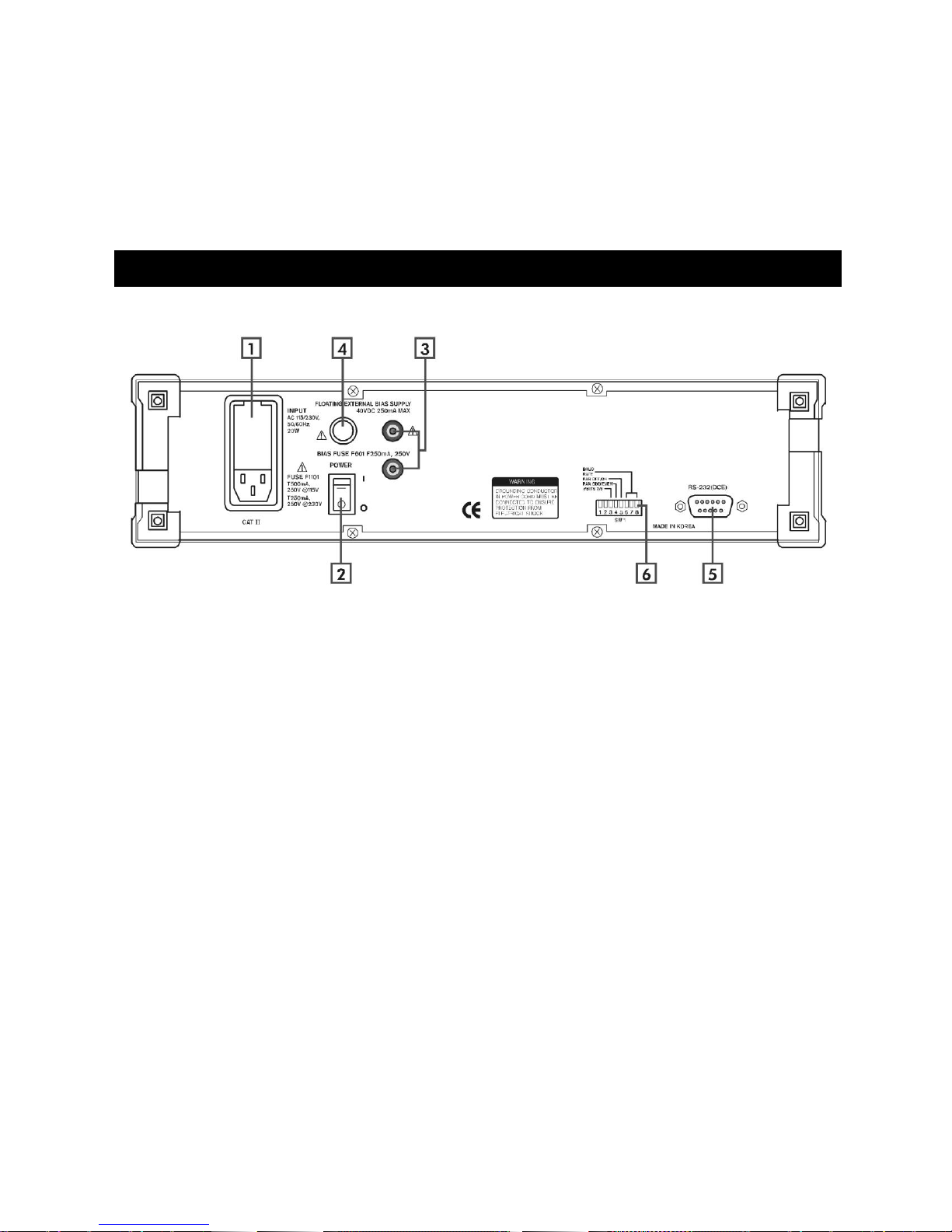
Rear Panel Components
The rear panel and its controls and connections are shown in the following illustration:
[1] AC POWER CONNECTOR The AC power cord is inserted into this connector. The
fuse and line voltage selector are located in the connector housing.
[2] POWER SWITCH Turns the meter on and off.
[3] EXTERNAL BIAS INPUT Two banana plugs are used to input an external bias
voltage. The bias supply voltage must be floating and well filtered. Neither input
connector can be referenced to ground.
[4] EXTERNAL BIAS FUSE Protects external bias circuit from currents greater than 250
mA.
[5] RS232 DB25 This connector allows the meter to communicate as a DCE (data
communications equipment, e. g. a modem) to a DTE (data terminal equipment, e.g.,
a computer) using the RS-232C protocol. For further information, refer to the
material on remote programming in the Reference Manual.
[6] SW1 The switches set the RS232C protocol parameters. The Baud rate, word
length and parity may be set.
12
Page 14

Specifications
Display
Measurement Modes: Auto, R+Q, L+Q, C+D, C+R
Equivalent Circuit: Series or Parallel
Parameters Displayed: Value, Deviation, % Deviation or Bin Number. Deviation
and % deviation are calculated from a stored relative value
Averaging: 2–10 Measurements
Measurement Range: R+Q: R: 0.0001–2000 M
Q: 0.00001–50
L+Q: L: 0.0001 µH–99999 H
Q: 0.00001–50
C+D: C: 0.0001 pF–99999 µF
D: 0.00001–10
C+R: C: 0.0001 pF–99999 µF
R: 0.00001–99999 k
Test Conditions
Accuracy
Test Frequency: 100 Hz, 120 Hz, 1 kHz, 10 kHz, 100 kHz
Frequency accuracy: ±100ppm.
Drive Voltage: Preset Levels: 0.10, 0.25, and 1.0 Vrms.
Vernier: 0.1 to 1.0 Vrms with 50 mV resolution.
Drive level accuracy: ±2%.
Measurement Rates: (a) Slow (2 meas./sec.), Medium (10 meas./sec.), or Fast
(20 meas./sec.) for test frequencies of 1 kHz and above.
(b) Approx. 0.6, 2.4, or 6 measurements per second at
100 Hz and 120 Hz.
Ranging Auto or Manual
Triggering Continuous, Manual, or Remote over RS232 or
Handler Interface
Bias Voltage Internal: 2.0 VDC ±2%
External: 0 to +40 VDC (fused @ 0.25 A)
Conditions: Allow 30 minutes of warmup before measurements; all accuracies are at
23° C (73F) ±5°C
Basic accuracy 0.05%. Refer to the accuracy section in the Reference Manual for
detailed specifications.
The following summarizes typical accuracy specifications:
13
Page 15

Feature
Specification
Fixture
4-wire Kelvin fixture for parts with radial and axial leads
Protection
Protected up to 1 Joule of stored energy, 200 V DC for charged capacitors;
fused at 0.25 A output current for biased measurement
Zeroing
Open and short circuit compensation. Compensation Limits: short circuit:
R<20, Z<50, open circuit: Z>10k
Binning
Up to 8 Pass Bins, QDR and General Fail Bins, all defined by the front panel or
computer interface. Binning setups may be stored in nonvolatile memory
Self Test
Tests the ROM, CPU, nonvolatile RAM, clock generator, A/D converter,
internal bias, multiplier, output drive circuitry, gain circuitry, and source
resistances.
Store and Recall
memory
Stores and recalls nine complete instrument setups. Recall 0 recalls the default
setup.
RS232 Interface
All instrument functions can be controlled or read over the interface.
Operating Conditions
0 to 50°C at a relative humidity of 0 to 80%
Power
20 Watts, 110/220 VA, 50/60 Hz
Dimensions
4 ¼ " H 14 ¼ " W 15" D
Weight:
12 ¾ lbs
Warranty
Two year parts and labor on materials and workmanship
Accuracy Value
better than 1% for R > 0.125 and R < 16 M
L > 2.5 H and L < 25 kH
C > 1.25 pF and C < 12.8 mF
better than 5 % for R > 21 m and R < 96 M
L > 420 nH and L < l50 kH
C > 0.21 pF and C < 77 mF
at the following conditions:
1.0V, 0.5V, or 0.25V output voltage
Slow or medium measurement speed
Q and D < 0.1 for R and C
Q > 10 for L
100Hz, 120Hz or 1 KHz test frequency for R
100 Hz test frequency for L
10 KHz test frequency for L
Features and Options
General Features
max
min
and C
and C
max
min
14
Page 16

Feature
Specification
IEE-488 interface
Instrument functions can be controlled and read over this interface
Handler/sorter interface
DB male connector provides the signal lines for binning, instrument
status and input trigger.
Note: option consists of both interfaces
Kelvin clips
Provides connection to devices that are not easily accommodated by the
test fixture. Polarity is indicated for biased measurements.
SMD Tweezers
Provides connection to surface mount components
BNC fixture adapter
Connects remote fixtures or devices to the 9216A
Options
15
Page 17

Basic Operations
Chapter
3
How the 9216A Operates and What It Can Do
The 9216A LCR meter is very versatile in that the user can customize the
measurement and operating modes to obtain the best results in a particular
situation. In this chapter, the basics of the meter’s operation are summarized.
Operation of the LCR Meter For the First Time
Before using 9216A LCR Meter, ensure that it is properly installed, and powered
on.
To get the maximum accuracy for your most critical measurements you
should know how to select the various options and to set up the test conditions
and the proper use of the test fixture you have chosen to use with your meter.
Unpacking and Inspection
After unpacking the 9216A LCR Meter, verify that all parts are included and have
not been damaged during transportation. Retain the packing materials.
Packing Contents:
9216A LCR Meter
Radial Fixture
Power Cord
User Manuals
Installation
To properly install and power on the meter, perform the following steps:
Be sure you have the appropriate operating environment.
Leave a space of at least 5.1 cm (2 in) on each side of the meter for proper
ventilation.
Check the fuse for proper type and rating.
Check for proper electrical connections.
Connect the proper power cord to the power connector on the rear panel.
16
Page 18

Startup Procedures
When turned on, the meter will first enter the self-test mode and perform the
following procedure: first, it will display the program version “0X” and the model
number “HC9216” for about three seconds. Next, the meter will display “test” and
“…..” while it performs the self-test. If all tests are successful, “test pass” will be
displayed as a result. In order for the self-test to operate correctly, it is important
to follow certain startup procedures.
Before Applying Power
Prior to turning the unit on, be sure there are no components in the input fixture.
Components in the fixture will cause the self-test to fail and display an error code.
Before Using the Test Fixture
When the self-test is completed, “over range” will be displayed, and the user can
proceed to set up the test conditions and to make measurements. For maximum
accuracy, however, a “null calibration” of the test fixtures needs to be performed
before taking any measurements.
Fixture Options
On the front panel of the instrument there are four BNC connectors designated IL,
PL, PH, IH. In what is known as a “4-wire Kelvin connection,” two of these
terminals provide current to and from the device under test, and two of the
terminals sense the potential (voltage) across the device. Separate wires are
used for sensing the voltage so to minimize the effect of the current in the sensing
wires inside the meter and to minimize stray impedance that can cause
measurement errors.
There are several fixtures available for special measurements: Radial fixture
(standard), Kelvin clips, SMD tweezers, and BNC adapter. The optional fixtures
may be purchased through our distributors.
The standard 9216A test fixture attaches to the four input terminals on the front
panel of the meter and provides two polarized, spring-loaded connection slots to
secure radial-leaded components under test while they are being measured. The
fixture also accommodates axial-leaded components whose leads are bent to
enable insertion into the fixture. Most components will plug into this test fixture,
thereby eliminating the need for special fixtures.
17
Page 19

Null Calibration Procedure
Whenever the test configuration is changed, including a change of the fixture,
open and short circuit “null” calibrations should be made prior to taking
measurements to compensate for stray impedances, such as component lead
impedance, and fixture, cable and other stray capacitance. Null calibration should
be performed after any change in fixture configuration or for changes in the drive
amplitude. This calibration corrects for all frequencies and all ranges-it is not
necessary to re-calibrate for changes in frequency. For critical measurements,
null calibration should be performed frequently at some interval during the course
of measurements.
The LCR meter store open and short circuit calibration data in nonvolatile
memory. These data values are stored with the STO key and recalled using the
RCL key, allowing null calibration data to be saved for different fixtures.
The null calibration procedure is on the menu that is invoked by pressing the
CAL (Calibrate) key in the SETUP group of keys on the front panel of the meter.
To perform a null calibration, press the CAL key until the message “nuLL cAL”
appears on the alphanumeric display. Pressing the ENTER key while this
message is being displayed causes the message to change to “Short cAL.”
The short-circuit null calibration is done by placing a wire in the fixture
(thereby shorting the fixture’s terminals) that is between 26 to 16 AWG (0.02" to
0.05" or 0.51 to 1.30 mm dia.). The calibration proceeds automatically after the
user presses the ENTER key and moves hands and any miscellaneous objects
away from the fixture. When the short circuit calibration is finished, the meter
prompts the user for the next operation by displaying the message “oPEn cAL.”
To perform the open-circuit null calibration, remove the shorting wire, press
ENTER and again move hands away from the fixture. When the unit has finished,
it displays the message “cAL donE.” To dismiss this message and return to a
normal display mode, press the DISP (Display) key.
Changing Test Setup Parameter Settings
When powered on, the 9216A LCR Meter initially uses the default test setup
parameters, which include selection of the automatic (AUTO) measurement
mode, and the result of the measurement is displayed on the alphanumeric
readout. For most measurements, the test conditions in the automatic mode are
sufficient. However, by pressing the parameter keys on the front panel, the user
may enter customized test setup parameter selections, and by pressing the
keypad keys, enter the desired values of test parameters. Test parameters that
are not associated with dedicated keys on the front panel or keypad, such as the
number of measurements being averaged, deviation measurements, etc., may be
entered by pressing the DISP key to enter the ENTRY mode. Table 3-1 below
shows appropriate settings for typical component values.
18
Page 20

Table 3-1 Test Setup Parameter Settings for Typical Component Values.
Component
Value
Meas. Mode
Equiv. Circuit
Frequency
Unknown
Any
AUTO
Series
1 kHz
Resistor
< 1 k
> 1 k
R+Q
Series
1 kHz
100 or 120 Hz
Inductor
< 10 H
10 H–1 mH
1 mH–1H
> 1H
L+Q
Series
100 kHz
10 kHz
1 kHz
100 or 120 Hz
Capacitor
< 10 pF
10 pF–400 pF
400 pF–1 F
> 1 F
C+D
C+D
C+D
C+R or C+D
Parallel
Series or parallel
Series
Series
10 kHz
10 kHz
1 kHz
100 or 120 Hz
Setting
Value
Parameter
AUTO
Frequency
1KHz
Drive Voltage
1.0Vrms.
Bias
OFF
Measurement Rate
SLOW
Averaging
OFF
Range Hold
OFF
Equivalent Circuit
SERIES
Display
VALUE
Trigger Mode
CONT
Binning
OFF
Default Setup
Holding down the backspace key () key while turning on the power to the meter
causes the meter to have the default setup values as listed in the table below.
Note: All user calibration settings and values will be lost.
To prevent the user calibration settings from being destroyed, after turning on
the meter without pressing the backspace key, press RCL [0] ENTER. This
key sequence will reset the meter to the default settings listed in the table below
without affecting user-entered calibration values. See the sections that follow for
more details on the settings listed in the table below.
Table 1-1: 9216A default settings
19
Page 21

Changing, Storing, and Recalling Custom Setups
Measurement Mode
The measurement mode is selected by pressing one of the four keys in the
PARAMETER group of keys on the front panel.
AUTO In this mode, the meter automatically selects the most appropriate
measurement on the device. The selection is made according to the following
criteria:
If |Q| < 0.125, the meter selects the R+Q measurement mode.
If Q > +0.125, the meter selects the L+Q measurement mode.
If Q < 0.125 and the meter is in the series equivalent circuit mode, the
C+R measurement mode is selected.
If Q < 0.125 and the meter is in the parallel equivalent circuit mode, the
C+D measurement mode is selected.
R+Q In this mode, resistance is displayed on the main parameter display and the
Q (quality factor) is displayed on the secondary parameter display. The R-value
is either the series or parallel equivalent resistance of the component under test.
The unit for R is , k, or M. The Q value is the dimensionless ratio of the
imaginary part of the component’s impedance to its real part. If Q has a positive
(+) value, the reactive component of the device under test is inductive. If Q has a
negative () value, it is capacitive.
L+Q In this mode, the series or parallel equivalent inductance value of a
component under test is displayed on the main parameter display units in units of
µH, mH, or H, and its dimensionless Q value is displayed on the secondary
parameter display.
C+D In this mode, the series or parallel equivalent capacitance value of a
component under test is displayed on the main parameter display in units of pF,
nF, or µF. On the secondary parameter display, the dimensionless ratio D 1/Q
is given. D is normally a small value for a good capacitor.
C+R In this mode, the capacitance is displayed on the main parameter
display and the equivalent resistance is displayed on the secondary parameter
display. The unit for resistance is unless the k indicator LED is lit.
Frequency
The output frequency is accurate to 100ppm (0.01%). Frequencies are set by
pressing the up/down keys () on the front panel keypad until the LED
corresponding to the desired frequency is illuminated. If the meter is on range
hold on Range 0, the 100 kHz frequency selection is disabled. If 100 kHz is
selected while in Range 0, the meter will beep and “r-f error” (range frequency
error) will be appear on the alphanumeric display. For more details, see the
section on Range.
20
Page 22

Drive Voltage
The 9216A meter has three fixed output rms voltages, 0.1 V, 0.25 V and 1.0 V.
These voltages are selectable from the front panel. A variable rms voltage is also
available, which is adjustable from 0.1 V to 1.0 V with 50 mV resolution. The
accuracy of the voltage levels is 2% or greater. To select a fixed voltage, press
and release the VOLT key located in the DRIVE VOLT section on front panel
keypad until the LED indicates the desired voltage.
To set the variable output voltage:
1. Press the CAL keypad button. The DISP LED will indicate the ENTRY
mode. On the alphanumeric display, “vtest” and the current voltage will be
shown.
2. Enter the desired output voltage from the numeric keypad (0.1 to 0.9 may
be entered) and press ENTER (M H µF key).
3. The output voltage may be set in 50mV steps. NOTE: If the drive voltage
is a value other than one of the three fixed voltages the CONS LED will light .
The output voltage is applied to the device under test through a source
impedance. Thus, the voltage across the device is always less than or equal to
the output drive voltage. The available source impedances for the four auto
ranging selections made by the meter are 25 (Range 3), 400 (Range2), 6.4
k (Range 1) and 100 k (Range 0), all of which are accurate to 2%. The
source impedance is automatically selected as a function of the measurement
range, unless the unit is in the constant voltage mode. In the constant voltage
mode, the source impedance is always 25 . See the section on Range for
determining which measurement range the meter is using.
Figure 3-1 shows the voltage across the Device Under Test (DUT) vs. the
DUT impedance for the different measurement ranges. The values are
normalized to a 1.0-V output drive setting for different applied voltages; that is, the
Figure plots the normalized voltage across the DUT, given by
(V
DUT/Vsource
) = R
DUT
/(R
source
+ R
DUT
)
Note that the voltage applied to the DUT is nearly equal to the output voltage at
the upper end of each range and decreases due to lower impedance toward the
lower end of the range. This is because of the impedance of the voltage source.
If the meter is in the constant voltage (CV) mode, the source impedance is always
set to 25 . For any DUT with impedance significantly larger than 25, the
voltage across the part is essentially equal to the output drive voltage.
For most devices, including resistors and capacitors, and for many inductors,
the 1.0 Vrms setting is the most appropriate setting. For some inductors and for
semiconductor or active devices, such as diodes and transistors, the 0.25 or 0.1
Vrms setting should be used. Certain devices require a specific test voltage, such
as Z5U ceramic disk capacitors (test voltage = 0.5 Vrms). In these cases, use a
variable voltage setting to obtain the exact voltage required. In general, use the
largest voltage possible for the best signal-to-noise ratio and accuracy.
21
Page 23

Figure 3-1. Normalized Voltage Across DUT vs. DUT Impedance
Bias
Internal or external DC bias voltages can be applied to capacitors. Electrolytic
and tantalum capacitors need a positive bias for accurate measurements,
although the meter bipolar test voltage will not typically be enough to damage
them. The 2 VDC internal or up to 40 VDC external bias voltage allows
measurements to be made while approximating actual operating conditions. The
external bias capability also allows C-V measurements to be made on
semiconductor devices.
Notice: Always be certain that the capacitor being tested is inserted with the
correct polarity. The bias voltage is always positive to the right and is marked on
the meter. Failing to observe the correct polarity can result in the destruction of
the component under test and possibility injury. Beware that capacitors can hold
their charge for a long time if removed from the fixture without discharging the DC
bias voltage.
Warning: Care must be taken to discharge the capacitor after making
measurements, especially when using a high external bias voltage. Failing to
discharge the device can result in damage to the device, damage to the meter, or
possible injury. The meter is protected internally against discharging capacitors
with up to 1 joule of stored energy (C*V/2).
The internal and external bias circuitry will work only if the unit is in the C+D or
C+R mode. Bias voltage cannot be applied if the meter is in the R+Q, L+Q or
AUTO mode.
The error message “bias for c” will appear if the bias button is pressed in an
inappropriate mode. Whenever the bias circuitry is active, the meter is in the
constant voltage mode, so that the voltage across the capacitor under test will
22
Page 24

stabilize in a reasonable amount of time. See the section on the constant voltage
mode for effects on ranges and accuracy.
It will take a short while for the internal circuitry and the DUT to stabilize after
applying the bias voltage. The time is primarily determined by the RC time
constant of the source resistance and the capacitor under test, plus the internal
AC coupling capacitor of 0.47 F. During this time, the reading on the meter may
change if it is continuously triggered. In this case, the initial readings should be
disregarded. If this is a problem, use the triggered mode (simply wait a short time
before triggering) or increase the settling time. See the section on measurement
rate for information on how to set the settling time. In addition, the capacitance of
some capacitors will slowly drift after a change in DC voltage.
Internal Bias
To apply the 2.0V DC internal bias voltage to the capacitor under test, first verify
that the capacitor is connected to the test fixture with correct polarity (positive to
the right). Press the INT key to apply the bias voltage. After a second or two, the
reading should be stable. Before removing it from the fixture, press the INT key a
second time to switch off the bias in order to discharge the capacitor.
External Bias
The meter has rear panel connectors to allow an external bias voltage of up to
+40 VDC to be applied across the capacitor under test. This supply must be
floating (neither side connected to ground) and must be current limited to less
than 250mA. A linear supply is recommended (instead of a switching supply).
The supply should be well filtered, to remove ripple from the bias voltage.
Connections to the bias supply are made on the rear panel with two banana jacks.
The red jack is the positive side of the supply and the black, the negative. There
is an internal diode within the unit to prevent a negative voltage from being
applied. The bias supply lines are fused with a 250mA fuse on the rear panel,
next to the banana jacks. If the meter does not yield stable readings when the
external bias switched is on, check this fuse. If the bias supply is connected
backwards, there is a good chance that the bias supply fuse will blow. Provisions
are needed to discharge the bias voltage from the capacitor under test before
removing it from the fixture. In general, external switches or discharging resistors
should be provided along with the bias supply to ensure safe operation.
To apply an external bias voltage, ensure that the bias supply is connected
correctly. Verify that the capacitor is installed with the correct polarity in the test
fixture (positive to the right). Next press EXT button to apply the bias voltage.
After a second or two, the reading should be stable. After the measurement is
complete, discharge the capacitor under test before removing it from the fixture.
For occasional nonproduction use with small capacitors (<500 µF) and low
bias voltages (<20 VDC), the meter can discharge the capacitor internally. Press
the EXT button to switch off the bias. The capacitor will then discharge through
the meter in the same manner as the internal bias.
23
Page 25
Another solution for somewhat larger bias voltages and/or capacitors is to
Frequency
Slow
Medium
Fast
100KHz
2.8
14
28
10KHz
2.8
14
27
1KHz
0.7
13
24
120Hz
0.7
2.8
7
100Hz
0.6
2.4
6
connect a resistor across the terminals of the bias supply. Switch off the bias
supply and allow the capacitor to discharge through the resistor before removing
it from the fixture. Make certain the discharge resistor is rated to handle the
steady state current that the bias voltage will generate through it and that the
supply can provide this additional current. For larger capacitors or higher supply
voltages it will be necessary to provide external switches to remove the bias
voltage and discharge the capacitor.
Measurement Rate
The 9216A has three measurement rates, which are selected by pressing the
Rate button. Slow, medium or fast rate may be selected. Table 3-2 lists the
maximum measurement rates attainable when the meter is not in the auto-range
mode, binning is disabled, and the RS232 interface is active. The measurement
affects the accuracy with slow and medium being the most accurate and fast
being the least accurate.
The actual measurement time can be calculated from the following equation:
T
= Ts + (Ni /f + Tdi + Trs + Td) Nm+ T
meas
calc
where Ts = settling time, Ni = number of test frequency cycles used in the
measurement, f = test frequency, Tdi = deintegration time, T
delay time, Nm = number of submeasurements per measurement, and T
calculation time. Tdi, Td and T
are constants, while Trs and f are set by the
calc
= resync time, Td =
rs
calc
=
measurement frequency. Ni and Nm are determined by the measurement rate
and Ts can be set by the user. See Table 3-3 for the appropriate values.
In addition to these factors, the measurement time is increased when using
auto ranging, binning RS232 interface. Binning adds about 2.5 ms to the total
measurement time. Autoranging adds n*(T
range changes required and T
is calculated according the equation given
meas
1 ms) where n = number of
meas
above.
It is difficult to determine the exact amount of time added when using RS-232
interfaces, since it is dependent on baud rate, the speed of the computer, and the
software. It takes about 5 ms for the meter to respond to send back over the
interface. In general, simple commands and responses like
Table 3-2 Measurement Rates (Number of Measurements/Sec)
24
Page 26

Table 3-3: Table for appropriate values
Variables
Appropriate Values for Variables
Nm
Slow
8
Medium
8
Fast
5
Ni
100/120Hz
1KHz
10KHz
100KHz
Slow
20
40
400
4000
Medium
4
4
40
400
Fast
2
2
20
200
Txx
Trs
Tdi
Td
T
calc
Ts 1/f
2 ms
2 ms
3 ms
2–99 ms
setting the frequency or checking what range the meter is on, can be returned in
about l0 ms. Longer responses, like XALL?, can take as long as 2 seconds over
the RS-232. If communications speed is critical, the binary data format, which
reduces the number of bytes transferred, can be used.
Settling Time
Occasionally it is advantageous to delay making a measurement after the meter
is triggered. This allows bias voltages on capacitors to stabilize or contacts on a
handler to debounce. The settling time is set in 1ms intervals from 2 to 99 ms.
To set the settling time,
1. Press the CAL key until the “settle” message appears in the left
alphanumeric display and the present settling time, in the right display.
2. Enter the new settling time value, from 2 to 99.
3. Press the ENTER key.
If an illegal value is entered, the meter will beep and display “range error.”
Triggering
The 9216A can make measurements continuously or in response to a trigger. To
change the trigger mode:
1. Press the MODE key in the TRIGGER group of front panel keys until the
desired mode LED is on; either CONT or TRIGGERED may be selected.
2. In the continuous mode, the meter will trigger itself at its maximum
measurement rate. In the trigger mode, the trigger can be from the TRIG
button or from the RS232 or Handler interface.
The TRIG LED will flash whenever the TRIG key is depressed and the meter will
make a single measurement.
25
Page 27

Note: When making a measurement, the meter will ignore any triggers it
receives until the current measurement is complete.
Store and Recall
The STO and RCL buttons allow nine complete instrument setups to be saved in
nonvolatile memory. All the test conditions, including binning, configuration and
open short circuit compensation, are saved.
To store a setup,
1. Press the STO button, which will display the “store” message.
2. Press the number where the setting is to be stored ([1]–[9]), then press the
ENTER button.
To recall a stored setting,
1. Press the RCL button, which will display “rcl”.
2. Press the number where the setting is stored ([1]–[9]), and then press the
ENTER button
Notes: 1. STO 0 ENTER will give an error since the factory default setting is
stored in location 0.
2. RCL 0 ENTER returns the default setup, including null calibration
values.
3. If a “cal error 4” appears during the self-test, or a “rcl error” message
appears when recalling a setup, the stored setup was lost and must be re-
entered.
Range
The meter has four measurement ranges, designated by the numbers 0 to 3. The
range may be selected manually or the meter cans auto range. Table 3-4
specifies the impedance ranges for each of the measurement ranges. Each of
the four ranges has a source impedance of approximately the mid-scale
impedance. Note that the measurement ranges determine an impedance range
(not a parameter value range), so the ranges of inductance and capacitance
depend upon the test frequency. The parameter f is the test frequency. In
addition, the impedance of a capacitor is inversely proportional to its capacitance,
so larger capacitors are measured in the lower impedance ranges.
Table 3-4: Measurement Range and Impedance Range
Range Source R Resistance Inductance Capacitance
3 25.0 10 –100.0 0.0001 H–(15.9/f) H 99999 F–(1.59/f) mF
2 400 100.0 –1.6 k (15.9/f) H–(255/f) H (1.59/f) mF–(99.5/f) F
1 6.4 1.6 k–25.6 k (255/f) H–(4074/f) H (99.5/f) F–(6.22/f) F
0 100 k 25.6 k–2000 M (4074/f) H–99999H (6.22/f) F–0.0001pF
* f is test frequency
26
Page 28

Autoranging Mode
During normal operations, the meter automatically changes to the most accurate
range for the device under test. When the meter measures an impedance that is
out of its current range, it goes up or down one range, and makes another
measurement. If this measurement is within the current range, it displays it. If not,
it changes ranges (if available), and repeats this process. There is built-in
hysteresis to avoid repeated range changes when a component is on a range
boundary. Up-range changes occur when the impedance measured exceeds
450% of the mid-scale impedance (i.e, the source impedance), or 12.5% over the
nominal range limit. Down-range changes occur when the measured impedance
drops below 22% of the mid-scale impedance, or 12.5% below the nominal range.
See Table 3-5 for the actual values where the range changes occur.
Table 3-5 Range Change Points When Autoranging
Ranging To Lower Impedances Ranging To Higher Impedances
Range Change Impedance Range Change Impedance
2 to 3 Z < 88 3 to 2 Z > 115
1 to 2 Z < 1.4 k 2 to 1 Z > 1.8 k
0 to 1 Z < 22.4 k 1 to 0 Z > 29.9 k
RANGE HOLD Mode
It is sometimes desirable to disable auto ranging since it takes nearly a complete
measurement cycle each time a range changes occurs. This can be annoying if
there are no parts in the fixture and the meter is continuously triggering, since an
empty fixture appears as a very large (nearly infinite) impedance. The meter will
auto range to range 0 (range 1 for 100 kHz) and then auto range back to the
appropriate range when a part is inserted in the fixture. Range holding is helpful if
measurement speed is a concern or if a number of parts with similar values are
being measured.
There are two ways to implement a RANGE HOLD mode:
1. The present measurement range can be held simply by pressing the
HOLD key. The LED above the HOLD key indicates that the meter is in the
RANGE HOLD mode.
2. A measurement range can also be directly entered from the ENTRY
display. Select the ENTRY display using the DISP key, then press HOLD.
The message “range” will appear in the left display, and the present range, 0–
3, will appear in the right display. Enter the desired range and press the
ENTER button.
Use the DISP key to return to the desired display. The RANGE HOLD LED will
be on. If an invalid range is entered, the meter will beep and display the message
“range error” and not accept the range entry. Range 0 cannot be entered when
the frequency is set to 100kHz. If this is attempted, the meter will beep and
display an “r-f error” (range-frequency error). To return the meter to the auto
ranging mode, simply press the HOLD button.
27
Page 29
Constant Voltage (CONS) Mode
Range
Source R
Resistance
Inductance
Capacitance
3
25.0
10 µ–360
.0001 µH–(57/f) H
99999 µF–(442/f) mF
2
25.0
360 –5.76 k
(57/f) H–(917/f) H
(442f) mF–(27.7/f) µF
1
25.0
5.76 k–90.0 2k
(917f) H–(1432/f) H
(27.7/f) µF–(1.77/f) µF
0
25.0
90.0 k–2000 M
(1432/f) H–99999 H
(1.77/f) µF–0.0001 pF
Ranging to a Lower Impedance
Ranging to a Higher Impedance
Range to Change
Impedance
Range to Change
Impedance
2 to 3
Z< 315
3 to 2
Z< 400
1 to 2
Z< 5.04K
2 to 1
Z< 6.4K
0 to 1
Z<78,.8K
1 to 0
Z<100K
Occasionally, a test will require using a specific drive voltage that is not possible
using the normal source resistance for that measurement range. In these cases,
press the CONS key and thereby set the source impedance to a fixed 25 . The
voltage across the component under test will be almost constant for all devices
with impedance substantially larger than 25. When the meter is in constant
voltage mode, the measurement range changes to avoid overloading the meter.
However, it also reduces the accuracy of the measurement by a factor of 2. See
the accuracy section in the Reference Manual for more detail. Tables 3-6 and 3-7
list the impedance ranges when using the constant voltage mode.
Under certain conditions, the “over load” message will be displayed. This
normally occurs when the unit is in the constant voltage mode with the range hold
on. To correct this, simply change to a higher impedance range, or use auto
ranging.
Table 3-6 Measurement and Impedance Ranges for Constant Voltage Mode
Table 3-7: Range change Points when Auto-Ranging in Constant Voltage Mode
28
Page 30

Series and Parallel Equivalent Circuits
1
Component
Equivalent Circuit
Q
Inductor
Series
L/R
Parallel
Rp/Lp
Capacitor
Series
1/CR
Parallel
CpR
p
1
Generally, as illustrated in Figure 3-2, any non-ideal component has a different
value for a series or parallel equivalent circuit due to the characteristics of the
component. The “quality” of an inductor is expressed by Q, the ratio of the
reactive (inductive) part of its impedance to its resistive part. The quality of a
capacitor is similarly defined, as summarized in Table 3-8. Often it is more useful
to calculate a capacitor’s “dissipative factor,” which is the inverse of its Q
. As Q
for inductors decreases towards 10 and Q for resistors or D for capacitors
increase towards 0. 1, the series and parallel circuit values begin to diverge. Most
components have an approximate value for the series equivalent circuit.
Manufacturers often specify which representation should be used when testing
their devices.
Figure 3-2 Series and Parallel Equivalent Circuits.
Table 3-8 Quality Factors for Equivalent Circuits.
Display Types
The DISP key can select one of five different types of displays. A display is
selected by repeatedly pressing the DISP key until till the LED indicates the
desired display option. These options are described as follows:
VALUE: This is the default display mode when the meter is turned on.
DEV: In the Deviation display mode, the difference between the currently
measured component value and a previously entered value is displayed. The
Deviation display is selected by repeatedly pressing the DISP key until the DEV
W. L. Everett and G. E. Anner, Communication Engineering (3rd edition), McGraw-Hill, 1956.
29
Page 31

LED is lit. The Deviation display is not available in the AUTO mode and if no
nominal value has been previously entered.
To Enter a Nominal Value,
1. Press and release the DISP key until the ENTRY LED is lit.
2. Select the measurement mode by pressing one of the keys in the
PARAMETER group of keys on the front panel.
3. The left alphanumeric display shows the currently stored nominal value.
4. Enter a new nominal value using the numeric keypad.
5. Press the appropriate enter key (Q, µH, pF, ), (k, mH, nF) or (M, H,
µF).
% DEV In this mode, the meter displays the difference between the currently
measured component value and a previously entered value as a percentage. It is
also not available in the AUTO mode or if no nominal value has been previously
been entered.
ENTRY In the ENTRY display mode, the user is permitted to enter nominal
values, measurement conditions and calibration data. If an out of range or
incorrect value is entered, the meter will beep and display a “range error”
message.
30
Page 32

1
PROTEK 9216A
Digital LCR Meter
User’s Manual
Volume 2: Reference
Table of Contents
Background on Components and Measurements ................................................................................................ 4
Definitions of Resistive and Reactive Parameters .......................................................................................... 4
Component Categories............................................................................................................................ 4
Units ........................................................................................................................................................ 5
Series and Parallel Equivalent Circuits ........................................................................................................... 5
Quality Factors ......................................................................................................................................... 6
Accuracy and Calibration ...................................................................................................................................... 8
Accuracy Specifications .................................................................................................................................. 8
General Accuracy Equation ..................................................................................................................... 8
Accuracy Equations for Specific Measurement Modes ......................................................................... 10
R + Q Accuracy............................................................................................................................... 10
Page 33

2
L+Q Accuracy ................................................................................................................................. 10
C+D Accuracy ................................................................................................................................. 10
C+R Accuracy ................................................................................................................................. 12
Accuracy When Holding a Nonoptimal Range ...................................................................................... 13
Verification of Meter Performance ................................................................................................................ 14
Functional Tests .................................................................................................................................... 14
Necessary Equipment: .................................................................................................................... 15
Front Panel Test ............................................................................................................................. 15
Self Tests ........................................................................................................................................ 15
Output Voltage ................................................................................................................................ 15
Resistance Measurement ............................................................................................................... 16
Capacitance Measurement ............................................................................................................. 16
Performance Tests ................................................................................................................................ 17
Necessary Equipment..................................................................................................................... 17
Frequency Accuracy ....................................................................................................................... 17
Amplitude Accuracy ........................................................................................................................ 17
Impedance Accuracy ...................................................................................................................... 18
Calibration Procedures ................................................................................................................................. 20
Introduction ............................................................................................................................................ 20
Calibration Enable........................................................................................................................... 20
Calbytes .......................................................................................................................................... 21
Necessary Equipment and Conditions ............................................................................................ 22
Amplitude Calibration ............................................................................................................................. 22
Frequency Calibration............................................................................................................................ 23
Standard Resistor Calibration ................................................................................................................ 24
Remote Control of the LCR Meter ...................................................................................................................... 26
Using the Interfaces ...................................................................................................................................... 26
RS232 Interface ..................................................................................................................................... 26
The RS232 Interface Standard ....................................................................................................... 26
Setting Up to Use the RS-232 Interface .......................................................................................... 27
List of Commands .................................................................................................................................. 29
Status Displays and Error Messages ........................................................................................................... 30
Definitions of Status Bytes ..................................................................................................................... 32
Serial Polling ................................................................................................................................... 31
Standard Event ............................................................................................................................... 31
Measurement .................................................................................................................................. 32
Page 34

3
Binning ................................................................................................................................................................ 33
Binning Options ............................................................................................................................................ 33
Binning Examples .................................................................................................................................. 33
Nested Bins .................................................................................................................................... 33
Sequential Bins With Different Nominal Values .............................................................................. 34
Sequential Bins With a Single Nominal Value................................................................................. 34
General Procedures .............................................................................................................................. 35
Setting Up the Bins ....................................................................................................................................... 36
Procedures ............................................................................................................................................ 36
Initial Setup ..................................................................................................................................... 36
Nominal Values for Pass Bins 0 to 7 ............................................................................................... 36
Limits for Pass Bins 0 to 7 ............................................................................................................... 36
Values for Fail Bins 8 and 9 ............................................................................................................ 36
Enable Binning ................................................................................................................................ 37
Using a Worksheet and Reusing Setups ........................................................................................ 37
Summary of Binning Setups .................................................................................................................. 38
Pass/Fail Setup ............................................................................................................................... 38
Nested or Overlapping Bins ............................................................................................................ 38
Sequential Bins ............................................................................................................................... 38
Troubleshooting .................................................................................................................................................. 39
General Problems ........................................................................................................................................ 39
Nothing Happens at Turn-on ................................................................................................................. 39
Reset Procedure ............................................................................................................................. 39
Internal Fuse Check ........................................................................................................................ 39
External Bias Fuse Check............................................................................................................... 39
Error Messages ............................................................................................................................................ 40
Operational Errors ................................................................................................................................. 40
Self-test Errors ....................................................................................................................................... 40
Calibration Errors ................................................................................................................................... 42
RS-232 Problems .................................................................................................................................. 42
9216A TEST PERFORMANCE RECORD................................................................................................... 44
Page 35

4
v
tVtV
cos||)(
tj
jtj
eeVeV
vv
||||
i
tItI
cos||)(
tj
jtj
eeIeI
ii
||||
1j
v
i
iv
i
v
j
tj
tj
e
I
V
eI
eV
tI
tV
ZZ
||
||
||
||)()(
||
||
||
||
0
I
V
e
I
V
Z
j
||
||
||
||
2/
I
V
je
I
V
Z
j
Chapter
1
Background on Components and Measurements
Properties of Resistors, Inductors, and Capacitors
The measurements made by the 9216A Digital LCR Meter are based on the definitions of
impedance and the properties of discrete components designed to provide impedances
in electronic circuits.
Definitions of Resistive and Reactive Parameters
Let the sinusoidal voltage and current in an electronic circuit at a particular frequency f be
represented in the complex or phasor notation, given respectively by
where
rent relative to the frequency f. The impedance of a circuit component is defined as the
complex number Z, in ohms, that gives the ratio of the voltage across the component to
the current in the component:
Component Categories
From equation (3), we observe that if the phases of the voltage across the component
and the current in it are equal, then the impedance is a real number:
, 2 f, and
and
(1a)
(1b)
(2a)
(2b)
are symbols for phases of the voltage and cur-
(3)
(4)
In this situation, the impedance is purely resistive, as an ideal resistor would be.
If the phase of the voltage is 90 degrees (/2 radians) ahead of the phase of the cur-
rent, then the impedance is a positive imaginary number:
(5)
Page 36

5
||
||
||
||
2/
I
V
je
I
V
Z
j
22
|| XRZ
LjRjXRZ
2
/1
/
pp
pppp
pp
pp
LR
LRjRR
LjR
LjR
In this situation of positive, imaginary impedance, the impedance is purely inductive, as
an ideal inductor would be. The impedance of an ideal inductor with inductance L is a
linear function of frequency, given by ZL jL.
If the phase of the voltage is 90 degrees (/2 radians) behind the phase of the current,
then the impedance is a negative imaginary number:
Units
(6)
In this situation of negative, imaginary impedance, the impedance is purely capacitive, as
an ideal capacitor would be. The impedance of an ideal capacitor with capacitance C is
the inverse of a linear function of frequency, given by ZC 1 / jC j /.C.
Actual circuit components are not purely resistive, inductive, or capacitive. Actual capacitors and inductors have impedances with resistive parts, and their impedances may
not be linear functions of frequency or independent of the voltage. The general expression for impedance, therefore, considers that it has a real, resistive part R and an
imaginary, reactive part: X:
Z R j X, (7)
Where X L for an inductor and X 1/C for a capacitor. Since the quantity X is
traceable to the ratio of a voltage to a current, it is expressed in ohms. Often, it is desirable to express the impedance in ohms as a scalar (real) quantity; in that case, its
magnitude
is used.
The unit of resistance is the ohm, with the symbol (omega). A 1- resistor produces a
one-volt voltage across it when the current is one ampere.
The unit of inductance is the Henry, with the symbol H. For a one-amp AC current, a
1-H inductor would produce an AC voltage across it whose magnitude is numerically
equal to 2 times the frequency in Hertz.
The unit of capacitance is the Farad, with the symbol F. For a one-amp AC current, a
1-F capacitor would produce an AC voltage across it whose magnitude is numerically
equal to the inverse of 2 times the frequency in Hertz.
Series and Parallel Equivalent Circuits
The impedances of Actual resistors, inductors and capacitors are combinations of resistance, inductance, and capacitance. The simplest models for actual inductors and
capacitors are the series and parallel equivalent circuits shown in Figure 1-1.
For example, the complex impedance of an inductor is
(series equivalent circuit) (8a)
(parallel equivalent) (8b)
Page 37

6
CjRjXRZ
/
2
1
1
1/1
/1
pp
ppp
pp
p
pp
pp
RC
RCjR
RCj
R
CjR
CjR
1
The complex impedance of a capacitor is
Quality Factors
Originally, the quality factor Q was defined for an inductor as a measure of the efficiency
of energy storage in the inductor when an AC current is passed through it. Mathematically, the definition is1
Figure 1-1 Equivalent circuits for inductors and capacitors.
(series equivalent circuit) (9a)
(parallel equivalent) (9b)
Q 2 (max. energy stored) (energy dissipated per Hz) (10a)
2 f (max. energy stored) (average power dissipated) (10b)
Since the average power dissipated in the inductor with series resistance R is |I|2R and
the maximum energy stored in the inductor is L|I|2, the quality factor for an inductor is given by
Q L / R. (11a)
By equating (8a) and (8b), the series equivalent circuit parameters R and L can be expressed in terms of the parallel parameters Rp and Lp. When that is done and substituted
in equation (10a), we find that the quality factor also is written
Q Rp / Lp. (11b)
While the concept of the quality factor was originally applied to inductors, it may be
extended so that the efficiency of energy storage in a capacitor may be expressed in
terms of the circuit components and frequency. Thus, if the series resistance and capacitance of a capacitor are, respectively, R and C as in Figure 1-1, then (10b) is evaluated to
be
Q 1 / CR. (12a)
By equating (9a) and (9b), the series equivalent circuit parameters R and C can be expressed in terms of the parallel parameters Rp and Cp. When that is done and substituted
in equation (12a), we find that the quality factor for a capacitor also is written
W. L. Everett and G. E. Anner, Communication Engineering, McGraw-Hill, New York, 1956.
Page 38

7
QjLjQRLjRZ /11
2
1 Q
R
R
p
2
2
1 Q
LQ
L
p
jD
C
jQRCjRZ
1
1/1
2
1 Q
R
R
p
p
CDC
2
1
Q Cp Rp. (12b)
Using the quality factor, the impedance of an inductor is seen to be
(13a)
and the inductor’s series equivalent circuit components can be expressed in terms of its
parallel equivalent circuit components as
,
(13b)
The impedance of a capacitor in terms of the quality factor is
(14a)
and the capacitor’s series equivalent circuit components can be expressed in terms of its
parallel equivalent circuit components as
,
(14b)
Page 39

Chapter
2
Accuracy and Calibration
How to Assess and Control the Accuracy
The accuracy achieved by the 9216A Digital LCR Meter depends on several factors. In
this chapter, equations are given for estimating the accuracy of a specific measurement,
and procedures are given for calibrating the meter.
Accuracy Specifications
Note: The accuracy of the 9216A that is stated in this chapter is valid for the following
conditions: (a) a warm-up time of at least 30 minutes, (b) a temperature of 23C 5C, (c)
the use of the built-in fixture, and (d) the completion of the open and short circuit calibrations. In addition, the component being measured must have the following characteristic:
D < 0.1 for a capacitor, Q < 0.1 for a resistor, or Q > 10 for an inductor.
General Accuracy Equation
The accuracy of a measurement is a function of the ―basic impedance accuracy‖ at the
specific frequency, measurement rate, signal amplitude, and the impedance of the device
under test (DUT) relative to the measurement range. The basic instrument accuracy can
be determined from graphs given below. Additional factors affecting the accuracy are related to the measurement conditions and the impedance of the DUT. From these, the
accuracy of a particular measurement in its optimal range is calculated. See below for
the effects on measurements made out of an optimal range.
The basic equation for impedance accuracy equation is given by
Accuracy in % [A Ki Kv + 100 (Kh Kl)], where (1)
A the basic impedance accuracy from Figure 2-1, which should be multiplied by two
if the unit is in constant voltage mode. Figure 2-1 is based on the fact that the
best accuracy occurs when the impedance to be measured is greater than ¼ the
source resistance and less than 4 times that resistance, and when the test fre-
quency is 1 kHz or less.
Ki integration time factor, as given in Table 2-1.
Kv drive voltage error factor, as given in Table 2-2. Note from Table 2-2 that Kv is
defined as equal to 1.0 for the primary drive voltages (1.0, 0.5, and 0.25 Vrms).
Kh, Kl extreme range error terms, as given in Table 2-3. Note from Table 2-3 that Kl
is negligible for impedances above 100 and Kh is negligible for impedances below 1 k, both at all frequencies.
8
Page 40

9
Meas. Rate
Frequency
Zm
Ki
Slow, Medium
All
All
1
Fast
100 Hz to 1 kHz
6.25 < Zm < 400 k
3
All other
2
Vout (Vrms)
Kv
0.55 to 1.0
1/Vout
0.3 to 0.5
0.5/Vout
0.15 to 0.25
0.25/Vout
0.10
0.11/Vout
Figure 2-1 Basic Impedance Accuracy
Table 2-1 Integration Time Accuracy Factor, Ki
Table 2-2 Drive Voltage Error Factor, Kv
Page 41

10
Frequency
Kl
Kh
100 Hz, 120 Hz, 1 kHz
(1 m/Zm)
(Zm/2 G)
10 kHz
(1 m/Zm)
(Zm/1.5 G)
100 kHz
(4 m/Zm)
(Zm/50 M)
Table 2-3 Extreme Range Error Terms, Kh and Kl
Accuracy Equations for Specific Measurement Modes
R + Q Accuracy
In the R + Q measurement mode, the basic impedance accuracy A in the equation for
impedance accuracy may be read from Figure 2-1 directly while interpreting the ―imped-
ance‖ as ―resistance.‖ The resistance accuracy is calculated from equation (1) above,
with the additional stipulation that if the measured Q has an absolute value greater than
0.1, then the basic resistance accuracy factor should be multiplied by the factor (1 + |Q|).
Let the basic resistance accuracy factor be denoted Ar. Then the accuracy of the measurement of Q is given by
Accuracy of Q [(Ar/100) (1+Q2)] (2)
Note that the accuracy of Q is specified as a magnitude, not as a percentage.
L+Q Accuracy
The basic impedance accuracy depicted in Figure 2-1 applies to inductance measurements when the impedance is interpreted to be 2 f L, where f is the test frequency in Hz
and L is the inductance in Henrys. For convenience, Figure 2-1 is redrawn in Figure 2-2
with lines of constant inductance superimposed. Also, Table 2-3 is recreated for inductive
impedances as Table 2-4. Note from Table 2-4 that the range error factor Kl is negligible
for inductances above 15.9/f H and Kh is negligible for inductances below 159/f H.
The accuracy of the inductance measurement is calculated from equation (1) above,
with the additional stipulation that if the measured Q has an absolute value less than 10,
then the basic inductance accuracy factor should be multiplied by the factor (1 + |1/Q|).
Let the basic inductance accuracy factor be denoted Al. Then the accuracy of the Q calculation is given by equation (2) with Al substituted for Ar.
C+D Accuracy
The basic impedance accuracy depicted in Figure 2-1 applies to capacitance measurements when the impedance is interpreted to be 1/2 f C, where f is the test frequency in
Hz and C is the capacitance in Farads. For convenience, Figure 2-1 is redrawn in Figure
2-3 with lines of constant capacitance superimposed. Also, Table 2-3 is recreated for capacitive impedances as Table 2-5. Note from Table 2-5 that the range error factor Kl is
negligible for capacitances below 1590/f F and Kh is negligible for capacitances above
159/f F.
Page 42

11
Frequency
Kl
Kh
100 Hz, 120 Hz
(1 H/Lm)
(Lm/2.6 MH)
1 kHz
(0.1 H/Lm)
(Lm/260 kH)
10 kHz
(0.02 H/Lm)
(Lm/10 kH)
100 kHz
(0.02 H/Lm)
(Lm/100 H)
Figure 2-2 Basic Impedance Accuracy for Inductances
Table 2-4 Extreme Range Error Terms for Inductances, Kh and Kl
The accuracy of the capacitance measurement is calculated from equation (1) above,
with the additional stipulation that if the measured D has a value less than 0.1, then the
basic capacitance accuracy factor should be multiplied by the factor (1 + D). Let the
basic capacitance accuracy factor be denoted Ac. Then the accuracy of the D calculation
is given by
Accuracy of D [Ac/100] (3)
Note that the accuracy of D is specified as a magnitude, not as a percentage.
Page 43
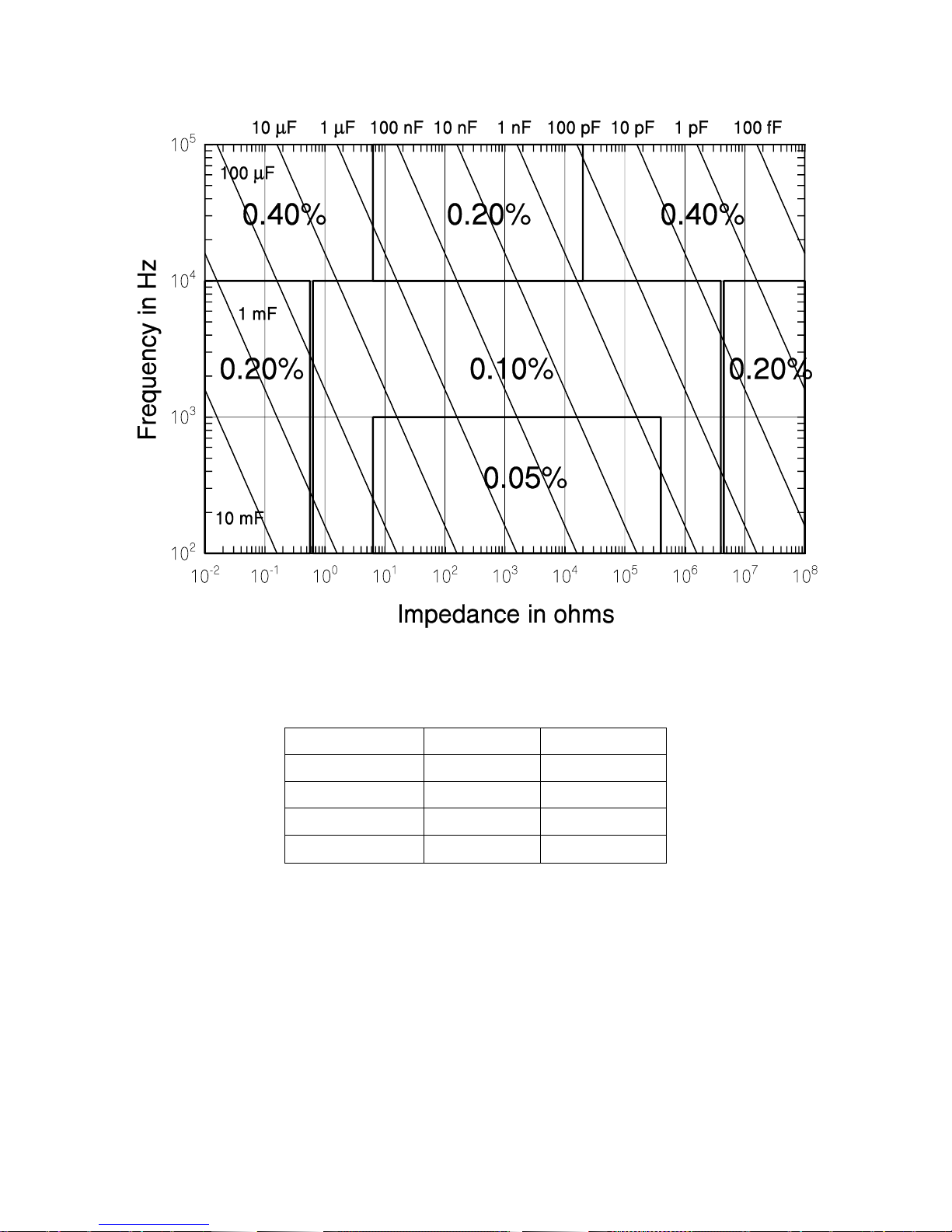
12
Frequency
Kl
Kh
100 Hz, 120 Hz
(2 pF/Cm)
(Cm/1600 mF)
1 kHz
(0.1 pF/Cm)
(Cm/160 mF)
10 kHz
(0.01 pF/Cm)
(Cm/16 mF)
100 kHz
(0.02 pF/Cm)
(Cm/200 F)
Figure 2-3 Basic Impedance Accuracy for Capacitances
Table 2-5 Extreme Range Error Terms for Capacitances, Kh and Kl
C+R Accuracy
The basic impedance accuracy depicted in Figure 2-1 applies to capacitance measurements when the impedance is interpreted to be 1/2 f C, where f is the test frequency in
Hz and C is the capacitance in Farads. For convenience, Figure 2-1 is redrawn in Figure
2-3 above with lines of constant capacitance superimposed. Also, Table 2-3 is recreated
for capacitive impedances in the C + R measurement mode as Table 2-6. Note from Table 2-6 that the range error factor Kl is negligible for capacitances below 1590/f F
For small values of D (D < 0.1), the accuracy of the capacitance measurement in the
C + R mode is calculated from equation (1) above, and the accuracy of the resistance
Page 44
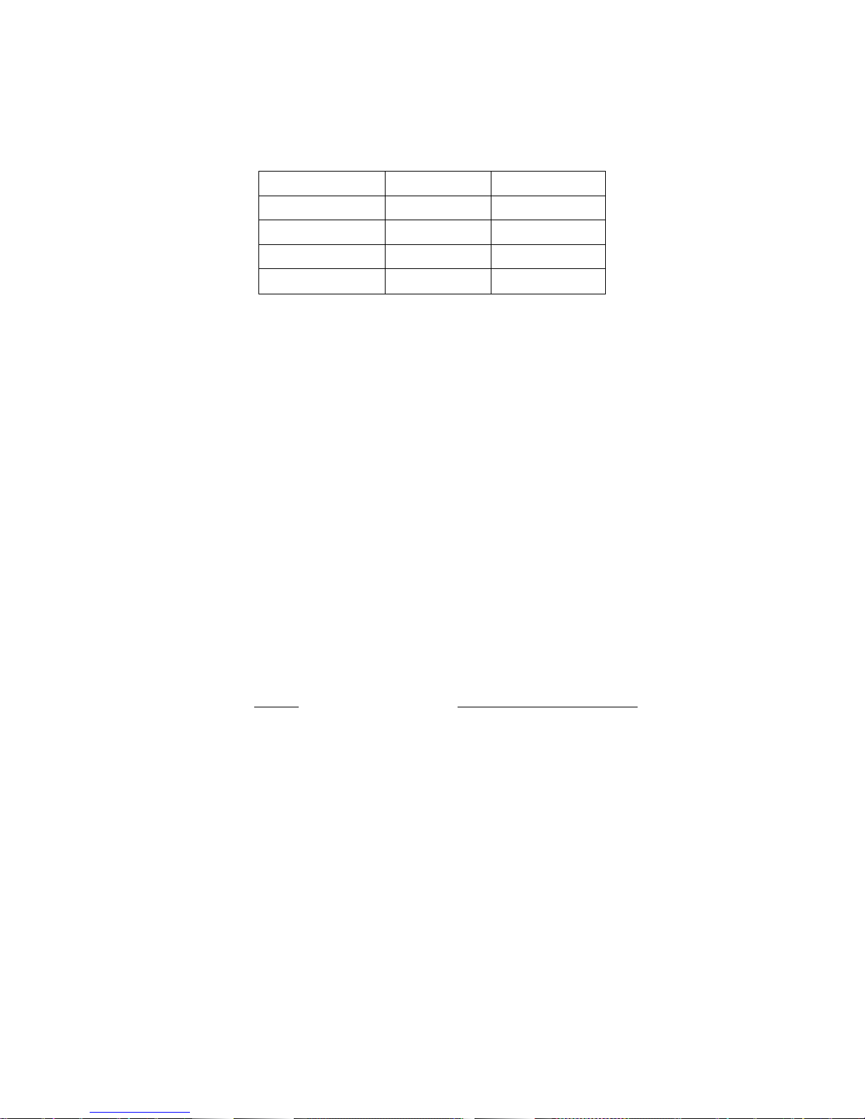
13
Frequency
Kl
Kh
100 Hz, 120 Hz
(2 pF/Cm)
(Cm/2000 mF)
1 kHz
(0.1 pF/Cm)
(Cm/200 mF)
10 kHz
(0.01 pF/Cm)
(Cm/10 mF)
100 kHz
(0.01 pF/Cm)
(Cm/100 F)
Table 2-6 Extreme Range Error Terms for Capacitances (C + R mode), Kh and Kl
measurement is given by
Accuracy of R in % [Ac (1 + 1/D)] (4)
where Ac is the accuracy of the capacitance measurement (above) and
D R/2 f C. (5)
For D > 0.1, the impedance accuracy must first be calculated. To do this, first calcu-
late the impedance of the DUT by adding the resistive and capacitive elements, either in
series or parallel, as appropriate. Use the impedance accuracy graph to obtain impedance accuracy, and let it be denoted Az. The accuracies of C and R are calculated from
the impedance accuracy as follows:
Accuracy of C in % [Az (1 + |D|)] (6)
Accuracy of R in % [Az (1 + 1/|D|)] (7)
Accuracy When Holding a Nonoptimal Range
When a component is measured outside of its nominal range (in range hold), the accuracy of the measurement is reduced. The nominal ranges are defined as approximately
four times above and below the nominal impedance value:
Range Nominal Impedance Range
R3 6.25 to 100
R2 100 to 1.6 k
R1 1.6 k to 25.6 k
R0 (100 Hz to 10 kHz) 25.6 k to 400 k
(R0 is not defined for 100 kHz.) Components that are measured while autoranging have
only one set of extreme range terms (Kh, Kl) per frequency.
For components measured in the range hold mode, the values of Kh and Kl are differ-
ent for each range. These values are calculated from parameters tabulated below in
Tables 2-7 to 2-9 for resistive, inductive, and capacitive measurements, respectively.
Page 45

14
Rl Kl Zm
Rh Kh Zm
Frequency
R3
R2
R1
R0
R3
R2
R1
R0
100, 120, 1 kHz
1 m
0.02
0.2
4
400 k
6.5 M
100 M
2 G
10 kHz
1 m
0.02
0.2
4
400 k
6.5 M
100 M
1.5 G
100 kHz
4 m
0.03
0.4
---
200 k
3 M
50 M
---
Ll Kl Lm
Lh Kh Lm
Frequency
R3
R2
R1
R0
R3
R2
R1
R0
100, 120 Hz
1 H
20 H
300 H
5 mH
630 H
10 kH
160 kH
2.6 MH
1 kHz
1 H
20 H
300 H
5 mH
630 H
10 kH
160 kH
2.6 MH
10 kHz
1 H
20 H
300 H
5 mH
630 H
10 kH
160 kH
2.6 MH
100 kHz
1 H
20 H
300 H
5 mH
630 H
10 kH
160 kH
2.6 MH
Cl Kl Cm
Ch Kh Cm
Frequency
R3
R2
R1
R0
R3
R2
R1
R0
100, 120 Hz
4 nF
240 pF
16 pF
2 pF
1600 mF
80 mF
6.7 mF
400 F
1 kHz
400 pF
24 pF
1.6 pF
0.1 pF
160 mF
8 mF
670 F
40 F
10 kHz
40 pF
2.4 pF
0.16 pF
0.01 pF
16 mF
800 F
40 F
2.6 F
100 kHz
8 pF
2.4 pF
0.02 pF
---
200 F
80 F
4 F
---
Table 2-7 Parameters for Calculating Kl and Kh for Resistive Measurements
Table 2-8 Parameters for Calculating Kl and Kh for Inductive Measurements
Table 2-9 Parameters for Calculating Kl and Kh for Capacitive Measurements
Verification of Meter Performance
The performance verification procedures in this section test and verify the performance of
9216A and compare it to the specifications listed in Volume 1 of this manual. The first set
of tests verifies the basic functionality of the unit. The second set of tests verifies the critical specifications of the 9216A. The results of each section can be recorded on the test
sheet located at the end of this manual.
Functional Tests
These simple tests verify the basic functionality of the 9216A. They are not intended to
verify the accuracy of the unit.
Page 46

15
Item
Critical Specifications
Recommended Model
Analog Oscilloscope with 10,
10MHz probes
100MHz Bandwidth
Tektronix 2445
24.9 Resistor
0.1%
Dale CMF55 or equivalent
402 Resistor
0.1%
Dale CMF55 or equivalent
6.34 k Resistor
0.1%
Dale CMF55 or equivalent
100.0 Resistor
0.1%
Dale CMF55 or equivalent
22 nF Capacitor
1% NPO
Murata Erie RPE series or equivalent
Necessary Equipment:
Front Panel Test
This test verifies the front panel display digits, LEDs, and keypad.
1. Turn on the unit while holding down the DISP key. A single segment in the third
digit of the left display should be on.
2. Press the down arrow key to light each segment (seven total) and the decimal
for the third and fourth digits of the left display, for a total of 16 segments. Only
one segment or decimal point should be on at a time. (Pressing the up arrow key
will step backward through the pattern.)
3. Press the down arrow key again (17th time) to light all the segments of all 12
digits. The AUTO LED will also be on.
4. Press the down arrow key repeatedly to light the 25 LEDs in the display and the
26 LEDs on the keypad. The LEDs turn on one at a time, from top to bottom and
left to right, first for the display, and then for the keypad. Only one LED should be
on at a time.
5. After all of the LEDs have been tested, further pressing of the front panel keys will
display the key code associated with each key. Each key has a different key
code, starting with 01 at the upper left, and increasing from top to bottom then left
to right.
6. The unit must be switched off to leave this mode.
Self Tests
The internal self tests verify the functionality of the 9216A. Turn on the unit. The ROM
program and model name will be displayed for about three seconds. Next the message
"tESt....' will be displayed while the unit performs its self tests. After the tests are com-
pleted the unit should display 'tESt PASS' to indicate that the tests were successful. If not,
an error message will appear. See the TROUBLESHOOTING section for a description of
the error messages.
Output Voltage
This test checks the 9216A output voltage for the correct frequency and amplitude.
Page 47

16
1. Set the 9216A to 1 kHz, 1 V and constant voltage. Set the scope to 1 V/div verti-
cal and 0.5 ms/div horizontal. Connect a 10 probe to the scope.
2. Place the tip of the probe into the "+" side of the fixture and connect the ground
clip to the center guard.
3. The scope should display a sine wave that occupies two divisions horizontally
and about 5.5 divisions peak to peak vertically (1.0 Vrms - 2.83 V peak to peak).
There should be no irregularities in the waveform.
4. Change the amplitude setting of the 9216A to 0.25 and 0.10 V in succession and
verify that the output is within 2% of nominal.
5. Set the amplitude back to 1.0 V. Change the 9216A and scope settings to verify
that the output at 100 Hz, 120 Hz, 10 kHz and 100 kHz is within 2% of nominal.
Resistance Measurement
This test verifies that the 9216A operates and is able to measure a component in each of
its ranges. The readings obtained should be within (tolerance of the component + toler-
ance of the 9216A).
1. Press the key sequence RCL 0 ENTER to put the unit in its default setup.
2. Perform open and short circuit calibrations for the fixture configuration to be used.
See Volume 1 for details on these null calibrations.
3. Set the unit to the R+Q measurement mode, series equivalent circuit, and 1 kHz
test frequency. Install the 24.9 resistor.
4. Verify that the meter reads the resistance correctly to within 0.15%. Verify that
Q is a small value, about +0.0001 or smaller. Install the 402 resistor. Verify
that the meter reads the resistance correctly to within 0.15%. Verify that Q is a
small value, about +0.0001 or smaller.
5. Change the equivalent circuit to parallel. Install the 6.34 k resistor. Verify that
the meter reads the resistance correctly to within 0.15%. Verify that Q is a small
value, about 0.0001 or smaller.
6. Install the 100 k resistor. Verify that the meter reads the resistance correctly to
within 0.15%. Verify that Q is a small value, about 0.0002 or smaller.
Capacitance Measurement
This test verifies that the 9216A is able to measure components at different frequen-
cies. The limits of the readings are the same as before: (component tolerance + meter
tolerance).
1. If the fixture configuration has changed, perform open and short circuit calibration.
2. Set the 9216A to the C+D measurement mode, parallel equivalent circuit, and 1
kHz test frequency.
3. Install the 22 nF capacitor. Verify that the unit reads the capacitance correctly to
within 1.10%. Verify that D is below 0.0001.
Page 48

17
Instrument
Critical Specifications
Time Interval Counter
Time Interval Accuracy: 1 ns max
DC/AC Voltmeter
5 ½ digit DC accuracy, true RMS AC to 100 kHz
Resistance decade box
Accuracy 0.02%: 1 to 1 M
Capacitance decade box
Accuracy 0.05%: 1000 pF to 10 F
4. Set the unit to 100 Hz. Verify that the capacitance reading is close to the value
measured above and within the tolerance stated above. Repeat for 120 Hz. D
values should be below 0.0001.
5. Repeat for 10 kHz. At 10kHz, the tolerance is 1.15%. For 100 kHz the tolerance
is 1.25%. D values should be below 0.001 for 10 kHz and 0.01 for 100 kHz.
Performance Tests
These tests are intended to measure the 9216A's conformance with its published
specifications. These test results, along with the results of the functional tests, can be
recorded on the test sheet at the end of this manual.
Necessary Equipment
Test conditions: at least 30 minutes of warm-up time, and a temperature in the range
of 23C 5 C.
Frequency Accuracy
This test measures the accuracy of the different output frequencies. They should be within 0.01% (100 ppm) of the nominal value.
1. Set the Z-9216 to its default conditions by pressing the key sequence RCL 0 EN-
TER. Set the unit to constant voltage mode, 1 kHz test frequency, and remove
any part from the fixture.
2. Install the BNC adapter on the fixture. Connect the IH lead to the frequency
counter.
3. Verify that the frequency counter reads 1 kHz 0.1 Hz (+0.01%). Record the re-
sult.
4. Repeat step 3 at 100 Hz, 120 Hz, 10k Hz and 100 kHz. The frequencies should
all be within 0.01% of the nominal frequency. Record the results.
Amplitude Accuracy
This test measures the amplitude accuracy of the drive output. It should be within
2.0% of the nominal value for all of the amplitude settings.
1. Connect the AC/DC voltmeter across the two sides of the fixture. A small piece of
wire inserted in each side of the fixture is a convenient way to connect the DVM.
Do not connect either end to ground. Set the DVM to AC volts, auto ranging.
Page 49

18
2. Set the 9216A to its default conditions by pressing the key sequence RCL 0 EN-
TER. Set the unit to constant voltage mode. The output voltage should be 1.0
Vrms at 1 kHz. Verify that the voltage reading is between 0.98 and 1.02 Vrms.
Record the result.
3. Repeat step 2 for 100 Hz, 120 Hz, and 100 kHz. All voltage readings should be
between 0.98 and 1.02 Vrms. Record the results.
4. Set the frequency to 1 kHz. Set the voltage sequentially to 0.25V and 0.10V.
The DVM should read within 2.0% of the nominal values (between 0.245 and
0.255 and between 0.098 and 0.102, respectively). Record the results.
5. Set the DVM to DC volts. Set the 9216A to the C+D measurement mode, 100
kHz test frequency, 0.10 V drive voltage with internal Bias on. Verify that the DC
voltage is 2.0 VDC 2%.
Impedance Accuracy
These tests confirm that the 9216A meets its impedance measurement accuracy specification. Precision impedance standards are required. The minimum and maximum
acceptable values are determined by adding the tolerance of the 9216A and that of the
standard. For example, at 1.000 k the tolerance is 0.05%, the tolerance of the resistance standard is 0.02%, and thus the total tolerance is 0.07% or 0.7 . So the
range of acceptable values is 999.3 to 1000.7 . If standards with different tolerances
are used, the acceptable limits will have to be adjusted.
Resistance Accuracy
1. Connect the Fixture Adapter to the 9216A. Install a BNC to stacking banana plug
adapter on the end of each BNC cable. Tape over (or cut off) the ground leads of
the plugs connected to the orange (PH) and purple (PL) cables. Connect the
ground leads of the red (IH) and blue (IL) cables to the case ground of the decade
box. Plug the orange and purple signal leads to the "+" and "" terminals on the
decade box. Plug the red signal lead into the orange signal lead and plug the
blue signal lead into the purple signal lead. Set the 9216A to its default conditions
by pressing RCL 0 ENTER, then press the R+Q key and set the test frequency to
1 kHz.
2. Unplug the red/orange lead pair from the "+" terminal of the decade box and plug
them into the blue/purple lead pair. Perform short circuit calibration. Remove the
red/orange lead pair form blue/purple lead pair and locate them at the same separation from the blue/purple pair as they will be during operation. Perform open
circuit calibration.
3. Connect the red/orange lead pair to the "+" terminal of the decade box. Set the
dials to all zeros. Note the resistance value that the 9216A measures. This is the
resistance of the switch contacts and connectors. Enter this as a relative value in
the entry display. Set the 9216A to the DEV display mode.
4. Set the decade resistor and the 9216A according to the values in the Resistance
Accuracy Table below. Verify that the readings fall within the acceptable values.
Record the results.
Page 50

19
resistance
range
conditions
Tolerance + R tol.
10.0
25.0
25.0
25.0
100.0
3
3
3
3
3
1 kHz series
1 kHz series
10 kHz series
100 kHz series
1 kHz series
9.9930 - 10.007
24.983 - 25.018
24.970 - 25.030
24.945 - 25.055
99.930 - 100.07
100.0
400.0
400.0
400.0
1.600 k
2
2
2
2
2
1 kHz series
1 kHz series
10 kHz series
100 kHz series
1 kHz parallel
99.930 - 100.07
399.72 - 400.28
399.52 - 400.48
399.12 - 400.88
1.5989 k - 1.6011 k
1.6000 k
6.4000 k
6.4000 k
6.4000 k
25.0000 k
1
1
1
1
1
1 kHz parallel
1 kHz parallel
10 kHz parallel
100 kHz parallel
1 kHz parallel
1.5989 k - 1.601 k
6.3955 k - 6.4045 k
6.3923 k - 6.4077 k
6.3859 k - 6.4141 k
24.983 k - 25.018 k
25.0000 k
100.0000 k
100.0000 k
400.0000 k
0
0
0
0
1 kHz parallel
1 kHz parallel
10 kHz parallel
1 kHz parallel
24.983 k - 25.018 k
99.930 k -100.07 k
99.880 k -100.12 k
399.72 k - 400.28 k
Resistance Accuracy Table
* if the Q value is greater than 0.1, the allowed tolerance must be multiplied by (1+Q)
Capacitance Accuracy
1. Connect the adapter ground leads of IH and IL to ground terminal of the decade
capacitor. Connect the IH and PH leads to the ―+‖ terminal of the decade capaci-
tor. Connect the IL and PL leads to the "" terminal of the decade capacitor box.
Set the 9216A to its default conditions by pressing the key sequence RCL 0 EN-
TER, then select the R+Q measurement mode and the 1 kHz test frequency.
2. Unplug the IH, PH leads from "+" terminal of the decade capacitor box and plug
them into the "" terminal of the decade capacitor box. Perform short circuit calibration. Unplug the IH, PH leads from "" terminal of the decade capacitor box,
then perform open circuit calibration.
3. Connect the IH, PH leads to the "+" terminal of the decade capacitor box. Set the
capacitance to zero.
4. Note the capacitance value the 9216A measures. This is the capacitance of the
switch contacts and connectors. Enter this as a relative value in the entry display.
Set the 9216A to the DEV display mode.
5. Set the decade capacitor and the 9216A according to the values in the Capaci-
tance Accuracy Table below. Verify that the readings fall within the acceptable
values. Record the results.
Page 51

20
Capacitance
Frequency
Range
9216A tol. + C tol.
1.0 nF
1.0 nF
1.0 nF
10.0n
10.0 nF
10.0 nF
10.0 nF
100 nF
100 nF
100 nF
100 nF
1.000 F
1.000 F
1.000 F
10.000 F
10.000 F
1 kHz
10 kHz
100 kHz
100 Hz
1 kHz
10 kHz
100 kHz
100 Hz
1 kHz
10 kHz
100 kHz
100 Hz
1 kHz
10 kHz
100 Hz
1 kHz
0
1
2
0
1
2
2
1
2
2
3
2
2
3
2
3
.99930 nF - 1.0007 nF
.99880 nF - 1.0012 nF
.99780 nF - 1.0022 nF
9.9930 nF - 10.007 nF
9.9930 nF - 10.007 nF
9.9880 nF - 10.012 nF
9.9780 nF - 10.022 nF
99.930 nF - 100.07 nF
99.930 nF - 100.07 nF
99.880 nF - 100.12 nF
99.780 nF - 100.22 nF
.99930 F - 1.0007 F
.99930 F - 1.0007 F
.99880 F - 1.0012 F
9.9930 F - 10.007 F
9.9930 F - 10.007 F
Capacitance Accuracy Table
Calibration Procedures
Introduction
Calibration of the 9216A is composed of several parts: open and short circuit calibrations,
standard resistor calibration, and amplitude calibration.
The open and short circuit calibrations (described in Volume 1 of this manual) are off-
set corrections to correct for any stray impedances of the test fixture. These Calibrations
may be performed at any time and should be done whenever the fixture is changed.
The standard resistor calibration sets the accuracy of the 9216A, since it allows the
LCR meter to determine the values of its internal standard resistors. Standard resistor
Calibration need only be performed periodically to account for component aging and drift.
Amplitude calibration sets the amplitude of the AC test signal, and only needs to be
done periodically. The amplitude calibration does not affect the 9216A’s accuracy.
Calibration Enable
The 9216A is shipped with amplitude calibration disabled. When calibration is disabled
only the open and short circuit calibrations are allowed. The internal calibration enable
jumper must be set to enable amplitude and resistor calibration. To set the jumper, remove the 9216A top cover by removing its four retaining screws (this will break the
calibration seal). In the rear center of the circuit board is a three pin jumper labeled
JP1001. Use the jumpers to connect the center pin and the "cal" pin to enable calibration.
Connecting the center pin and the "normal" pin will disable calibration.
Page 52

21
Frequency
Amplitude
100 Hz
120 Hz
1 kHz
10 kHz
100 kHz
0.10 V
0 1 2 3 4
0.15 V
5 6 7 8 9
0.20 V
10
11
12
13
14
0.25 V
15
16
17
18
19
0.30 V
20
21
22
23
24
0.35 V
25
26
27
28
29
0.40 V
30
31
32
33
34
0.45 V
35
36
37
38
39
0.50 V
40
41
42
43
44
0.55 V
45
46
47
48
49
0.60 V
50
51
52
53
54
0.65 V
55
56
57
58
59
0.70 V
60
61
62
63
64
0.75 V
65
66
67
68
69
0.80 V
70
71
72
73
74
0.85 V
75
76
77
78
79
0.90 V
80
81
82
83
84
0.95 V
85
86
87
88
89
1.00V
90
91
92
93
94
Calbytes
The 9216A calibration is controlled by calibration constants ("calbytes") that the firmware
uses to adjust the impedance calculations. These calbytes are stored in the 9216A RAM.
Recalibration of the 9216A involves determining new values of the calbytes and storing
them in the RAM. The calbyte values that are determined at the time of the 9216A manufacture are also stored in ROM and may be recalled at any time. The standard resistor
calbytes are automatically determined by the standard resistor calibration subroutines.
The amplitude calbytes must be manually determined.
The 95 amplitude calbytes, which are one-byte integers in the range of 0 to 255, are
directly adjustable from the front panel and are organized as shown in Table 2-10. The
120 floating point frequency correction, reference resistor values, and open and short circuit calbyte values, whose organization is given in Table 2-11, are automatically
determined by the 9216A's calibration subroutine. These calbytes cannot be directly
changed from the front panel, but they may be changed via the computer interfaces.
Table 2-10 Organization of Amplitude Calbytes to Amplitude and Frequency
Page 53

22
Calbyte Number
Name
Meaning
0
Frequency Correction
Deviation from nominal, in ppm
1–40
Reference Resistor Values
Impedance values organized in real and imaginary
pairs
41–80
Open Circuit Values
Admittance values organized as real and imaginary pairs
81–120
Short Circuit Values
Impedance values organized in real and imaginary
pairs
byteCurrentCal
Vmeas
omVn
NewCalbyte
Table 2-11 Organization of Floating Point Calbytes
Necessary Equipment and Conditions
To perform the amplitude, frequency, or standard resistor calibration, the following
equipment is needed:
A time interval counter, with an accuracy of 1 ns or better.
An AC/DC voltmeter, with 5 ½ -digit DC accuracy and true RMS AC measure-
ments to 100 kHz.
Standard resistors, with resistance known to 0.01% and Q accuracy known to 25
ppm. The resistor values needed are 95.300 k (R0), 5.970 k (R1), 374.0
(R2), and 25.10 (R4).
A fixture-to-BNC adapter.
The conditions for calibration include a warm-up time of at least 30 minutes and an ambient temperature of 23C 2C.
Amplitude Calibration
This procedure calibrates the output amplitude at the different frequencies and output
voltages. To adjust the calbytes, press the CAL key until the message "cl I" appears in
the display, where I is an integer. The present value of that calbyte will appear in the right
display. The and frequency keys step through the different amplitude calbytes. New
values are entered using the numeric entry keys.
1. Connect the AC/DC voltmeter across the two sides of the fixture. A small piece of
wire inserted in each side of the fixture is a convenient way to connect the DVM.
Do not connect either end to ground. Set the meter to AC volts, auto ranging.
Set the 9216A to its default conditions by pressing the keys, RCL 0 ENTER. Set
the unit to constant voltage mode.
2. Measure the amplitude and frequency for amplitude calbyte 0 (0.10 V and 100
Hz). If the value is not within 2% of the nominal value, enter the new calbyte using the formula:
, rounded to the nearest integer
Page 54

23
Calbyte
Nominal Voltage
Limits
0-4
5-9
10-14
15-19
20-24
25-29
30-34
35-39
40-44
45-49
50-54
55-59
60-64
65-69
70-74
75-79
80-84
85-89
90-94
0.100
0.150
0.200
0.250
0.300
0.350
0.400
0.450
0.500
0.550
0.600
0.650
0.700
0.750
0.800
0.850
0.900
0.950
1.000
0.098-0.102
0.147-0.153
0.196-0.204
0.245-0.255
0.294-0.306
0.343-0.357
0.392-0.408
0.441-0.459
0.490-0.510
0.539-0.561
0.588-0.612
0.637-0.663
0.686-0.714
0.735-0.765
0.784-0.816
0.833-0.867
0.882-0.918
0.931-0.969
0.980-1.020
3. Verify that the amplitude is within 2% of the nominal value. See Table 2-12 below
for the acceptable limits for each amplitude.
4. Repeat steps 2 and 3 for 120 Hz, 1 kHz, 10 kHz, and 100 kHz (Calbytes 1, 2, 3
and 4) at this amplitude (0.10 V). Note that, for each amplitude, the calbyte numbers are in order of ascending frequency.
5. Repeat steps 2 to 4 for each amplitude in the table. At each amplitude, repeat the
measurement for each frequency, starting with 100 Hz and increasing to 100 Hz.
Table 2-12 Amplitude Limits
Frequency Calibration
This procedure measures the accuracy of the 9216A clock. The exact clock frequency is
used in calculating capacitance and inductance values. The clock correction factor is
stored in parts per million (ppm).
1. Set the 9216A to its default conditions by pressing the keys RCL 0 ENTER. Set
the unit to constant voltage mode at 1 kHz, and remove any part from the fixture.
2. Install the BNC adapter to the fixture. Connect the IH lead to the frequency counter.
3. Determine the new calbyte by the formula, Calibyte (frequency 1000.000)
1000.
4. To adjust the clock calbyte, press the CAL key until "Std cAL" appears on the
display. Press ENTER once to get into this menu structure, and then press CAL
Page 55

24
until the message "df‖ appears on the left alphanumeric display and the current
value on the right display. Enter the new value, in ppm using the entry keys. To
exit the standard cal menu, press CAL until the "quit CAL" message appears, and
then press ENTER.
Standard Resistor Calibration
This procedure determines the value of the internal standards for the different frequencies and ranges. The 9216A does this by measuring a precisely known resistor and
recomputing the values it uses when calculating the impedance of a part. These values
are the primary accuracy standard of the instrument, so the exact value of the calibration
resistor, both real and imaginary parts, must be known. In addition, the 9216A and the
calibration resistors must be placed in a temperature controlled room and allowed to stabilize at least 30 minutes before attempting calibrate.
The standard cal menu is entered as follows: Press the CAL key until "Std cAL" ap-
pears on the alphanumeric display. Press ENTER once to get into this menu structure.
Next press CAL until the "rAngE‖ message appears on the left display. From here the
desired range can be entered (using the 0 to 3 numeric keys and ENTER) and will ap-
pear on the right display.
After the range has been entered, pressing CAL will cycle through a series of menus.
Pressing ENTER in any of these will either load that value or begin the action listed. Two
different parameters must be set, "r Std" (standard resistor resistance value) and "q Std"
(Q of the standard resistor). Resistance values are entered using the , k, and M
keys and Q is entered in ppm. Negative Q's denote capacitive resistors and positive Q's
denote inductive ones. The different actions are "StArt cAI" (start cal), "Fctry cAL" (factory cal) and "quit cAL" (quit cal). These activities will, in order, begin calibration of the
current range, recall the factory default values, or exit the cal menu.
1. Inspect the fixture contacts for dirt or waxy build up. If the fixture appears dirty,
clean it. Remove any adapters or components from the fixture.
2. Perform open and short circuit calibration.
3. Plug the R0 calibration resistor into the fixture. Enter the cal menu as described
above and enter range 0.
Press CAL until "r Std" (resistance standard) is displayed. Enter the re-
sistance of R0.
Press CAL to display "q Std: (Q standard) and enter the Q of the standard in
ppm.
Press CAL to display "StArt cAL" (start cal). Begin the calibration by pressing
ENTER, making sure to keep hands and any other objects away from the fix-
ture.
4. Repeat step 3 for the other three ranges (1, 2 and 3). When finished, exit the cal
menu by pressing CAL until "quit cAL" is displayed and then press ENTER.
5. After calibration, verify that the calibration is accurate. Perform open and short
circuit calibration. Insert the standards in the fixture and measure them at 1 kHz,
series equivalent circuit. The R and Q readings should agree to within one least
significant digit of the standard values.
Page 56

25
6. Check the standards at different frequencies. Use the series equivalent for the
two smaller resistors and the parallel equivalent for the two larger ones. R should
remain relatively constant and Q should scale with frequency (i.e. Q at 10kHz is
10 Q at 1 kHz). If any of the values are too far from the nominal values, recalibrate that range.
7. Before making measurements, run open and short circuit calibration with the fixture configuration to be used.
Page 57

26
Chapter
3
Remote Control of the LCR Meter
Remote Programming Reference
The 9216A LCR meter may be controlled and programmed remotely using either an
RS232 Any computer supporting either of these interfaces may be used with the 9216A.
Both interfaces are simultaneously active and are accessed via the connectors on the
rear panel. The 9216A responds to commands from either interface and returns answers
to the interface from which the command came. All front and rear panel features (except
power) may be controlled.
Using the Interfaces
RS232 Interface
The RS232 interface specifies how to transfer data between a data terminal equipment
(DTE), such as a computer, and a data communications equipment (DCE), such as a
modem. The interface includes two signal lines that can be used for half-duplex (oneway) or full duplex (simultaneous two-way) operation. Additional lines are used for controlling the flow of the data in the sense that data cannot be transferred unless the
appropriate flow control line is first asserted (changed from 0 to 1).
The RS232 Interface Standard
The RS232 interface specifies a 9-pin connector as the interface in data communications
networks—a 9-pin D-SUB male connector at the DTE (data terminal equipment) and a 9-
pin D-SUB female connector at the DCE (data communications equipment)—with the
pins designated as shown in Table 3-1.
The most common RS232 signals are the following:
Request to Send (RTS) and Clear to Send (CTS): The RTS signal line is asserted by the
computer to inform the modem that it wants to transmit data. If the modem decides that it
is read to receive data, it will assert the CTS line. Typically, once the computer asserts
RTS, it will wait for the modem to assert CTS before transmitting data.
Data Terminal Ready (DTR) and Data Set Ready (DSR): This line is asserted by the
computer to inform the modem that it is ready to receive data. In response, the modem
will assert DSR to indicate that it is turned on.
Data Carrier Detect (DCD): This control line is asserted by the modem, informing the
computer that it has established a physical connection to another modem and is ready to
transfer data.
Page 58

27
Pin
Signal
Direction
Description
1
DCD
Data carrier detect
2
RX
Receive Data
3
TX
Transmit data
4
DTR
Data terminal ready
5
GND
—
Signal ground
6
DSR
Data Set Ready
7
RTS
Request to send
8
CTS
Clear to Send
9
RI
Ring indicator
Table 3-1 RS-232 Signals and Pin Assignments
In the application of the RS232 interface to the remote control of the LCR Meter, the
meter plays the role of a modem, and the flow of data is primarily measurements transmitted from the meter to the computer.
Setting Up to Use the RS-232 Interface
The 9216A is configured as a DCE (transmit on pin 3, receive on pin 2) and supports the
CTS/DTR hardware handshaking discussed above. The CTS signal (pin 8) is an output
of the meter indicating that the 9216A is ready, while the DTR signal (pin 4) is an input to
the meter that is used to control the 9216A transmissions. If desired, the handshake pins
may be ignored and a simple three-wire interface (pins 2, 3 and 5) may be used.
Before communicating with the 9216A, the RS232 characteristics must be set. As
shown in Table 3-2, the RS232 interface is configured using the rear panel switches
SW1-1 to SW1-7. The last three switches set the baud rate to 300, 600, 1200, 2400,
4800, or 9600 baud. Parity may be enabled or disabled, and set to even or odd, and, the
number of bits in a data byte may be set to 7 or 8.
Note: the 9216A must be set to eight data bits if binary data output formats are used.
Page 59

28
Using Commands
Communications with the 9216A use ASCII characters. Commands may be in either
UPPER or lower case and may contain any number of embedded space characters. A
command to the 9216A consists of a four-character command mnemonic, arguments if
necessary, and a command termination. The terminator may be either a carriage return
<CR> or line feed <LF> on RS232, or a line feed <LF> or EOI. No command processing
occurs until the meter receives a command termination. Commands may require one or
more parameters. Multiple parameters are separated by commas ",".
Multiple commands may be sent on one command line by separating them by semicolons ";". The difference between sending several commands on the same line and
sending several independent commands is that when a command line is parsed and executed the entire line is executed before any other device action proceeds.
There is no need to wait between commands. The 9216A has a 256-character input
buffer and processes commands in the order received. If the buffer fills up, the 9216A will
to hold off handshaking on RS232. If the buffer overflows the buffer will be cleared and
an error reported. The output buffer may be cleared by using the Device Clear universal
command.
The present value of a particular parameter may be determined by querying the
9216A for its value. A query is formed by appending a question mark "?" to the command mnemonic and omitting the desired parameter from the command. If multiple
queries are sent on one command line (separated by semicolons, of course) the answers
will be returned in a single response line with the individual responses separated by semicolons. The default response delimiter that the 9216A sends with any answer to a query
is carriage return-line feed <CR> <LF> on RS232 and line feed plus EOI, except for binary answers, which are delimited by a line feed signal <LF> on both interfaces. All
commands return integer results except as noted in individual command descriptions.
Example command formats are given in Table 3-5.
Page 60

29
FREQ 2 <LF>
Sets the drive frequency to 100 Hz (one-parameter command)
FREQ ? <LF>
Queries the drive frequency (query of one-parameter command
BLIM 0, 3, 100 <LF>
Sets the upper limit of bin 3 to 1000 (three-parameter command
BLIM ? 0, 3 <LF>
Queries the upper limit of bin 3 (query of a three-parameter command)
*IDN ? <LF>
Queries the device identification (query with no parameters)
*TRG <LF>
Triggers a measurement (command with no parameters)
FREQ 1; FREQ ? <LF>
Sets frequency to 120 Hz, then queries the frequency.
VARIABLES
i, j Integers
x Real Number
MEASUREMENT SETUP
$STL(?) {i}
AVGM(?) {i}
BIAS(?) {i}
CIRC(?) {i}
CONV(?) {i}
FREQ(?) {i}
MMOD(?) {i}
NAVG(?) {i}
PMOD(?) {i}
RATE(?) {i}
RNGE(?) {i}
RNGH(?) {i}
VOLT(?) {x}
Set (query) settling time to between i 2 and i 99 milliseconds.
Set (query) averaging on (i 1) or off (i 0)
Set (query) DC bias to internal (i 1), external (i 2), or off (i 0)
Set (query) equivalent circuit to series (i 0) or parallel (i 1)
Set (query) constant voltage mode on (i 1) or off (i 0)
Set (query) drive frequency to 100 Hz(0), 120 Hz(1), 1 kHz(2) or 100 kHz(4)
Set (query) measurement mode to continuous (i 0) or triggered (i 1)
Set (query) number of measurements to be averaged from i 2 to i 10
Set (query) parameter mode to Auto(0), R+Q(1), L+Q(2), C+D(3), or C+R(4)
Set (query) measurement rate to Fast(0), Medium(1) or Slow(2)
Set (query) meas. range to 100 k(0), 6.4 k (1), 400 , (2) or 25 (3)
Set (query) range hold to enabled (i 1) or disabled (i 0)
Set (query) drive voltage to 0.1 V x 1.00 V with 0.05 V resolution.
MEASUREMENT CONTROL
PREL(?) {x}
STRT
STOP
*TRG
Set (query) nominal parameter value for deviation and %deviation to x (,F,H)
Starts a measurement.
Stops the current measurement.
Same as STRT.
MEASUREMENT OUTCOME
OUTF(?) {i}
XALL?
XBIN?
XDLT?
XMAJ?
XM1N?
XPCT?
Set (query) the output format to verbose (0) or concise (1) ASCII, or verbose (2) or concise
(3) binary.
Returns major and minor parameters plus bin number.
Returns bin number of current measurement.
Returns deviation between major parameter and nominal value.
Returns value of the major parameter.
Returns value of the minor parameter.
Returns percent deviation between major parameter and nominal value.
List of Commands
Table 3-5 Examples of Command Formats
Page 61

30
BINNING
BCL
BING(?) {i}
BLIM(?) i j {x}
BNOM(?) i {x}
Clears nominal values and limits for all bins. All bins are closed.
Set (query) binning to enabled (i 1) or disabled (i 0).
Set (query) upper (i 0) or lower (i 1) limit of bin j (0-7) to x%.
Set nominal value of bin i to x
SETUP CONTROL
*IDN?
*OPC(?)
*RCL {i}
*RST
*SAV{i}
*WAI
Returns the 9216A identification string.
Set bit in Standard Event Status byte when measurement is complete.
Recall setting i.
Reset unit to default configuration.
Save current setup as setting i.
Wait until all measurements are completed before proceeding.
STATUS
*CLS
*ESE(?) {i}
*ESR? {i}
*PSC(?) {i}
*SRE(?) {i}
*STB? {i}
SENA(?) {i}
STAT? {i}
Clear all status registers.
Set (query) the Standard Event Status Byte Enable register to value i (0-255).
Query Standard Status byte. If i is included, only bit i is queried.
Set (query) power-on status clear bit to clear (i 1) or maintain (i 0) status val-
ues.
Set (query) the Serial Poll Enable register to value i (0-255).
Query Serial Poll status byte. If i is included, only bit i is queried.
Set (query) LCR Status Enable register to value i (0-255).
Query LCR Status byte. If i is included, only bit i is queried.
Status Displays and Error Messages
Adjacent to the right alphanumeric displays, the 9216A has three front panel status LEDs
that provide positive indication of commands and communications to help verify operations during the development of control programs. The ACT LED flashes whenever a
character is received or sent over either interface. The ERR LED flashes when an error
has been detected, such as an illegal command, or parameter out of range. The REM
LED is lit whenever the 9216A is in a remote state (front panel locked out).
The 9216A reports two types of errors that may occur during command execution:
command errors and execution errors. Command errors are errors in the command syntax. For example, unrecognized commands, illegal queries, lack of terminators, and nonnumeric arguments are examples of command errors. Execution errors are errors that
occur during the execution of syntactically correct commands. For example, out of range
parameters and commands that are illegal for a particular mode of operation are classified as execution errors.
The NO COMMAND bit is a bit in the serial poll register that indicates that there no
commands waiting to be executed in the input queue. This bit is reset when a complete
command is received in the input queue and is set when all of the commands in the
queue have been executed. This bit is useful in determining when all of the commands
sent to the 9216A have been executed. This is convenient because some commands,
Page 62

31
bit
name
usage
0
Ready
The 9216A is ready to perform a measurement
1
Not used
2 Not used
3 LCR
An unmasked bit in the LCR status register has been set.
4
ESB
An unmasked bit in the standard status byte has been set.
5
RQS / MSS
SRQ (Service Request) bit.
6
No command
There are no unexecuted commands in the input queue.
bit
name
usage
0
OPC
Set by the OPC command when all measurements are complete
1
Not used
2 Query Error
Set on output queue overflow (too many responses waiting to be transmitted.)
3
Not used
4
Execution err
Set by an out of range parameter, or non-completion of some command due a
condition such as an incorrect operating mode.
5
Command err
Set by a command syntax error, or unrecognized command
6
URQ
Set by any key press
7
PON
Set by power on
such as taking a measurement, or auto calibration, take a long time to execute and there
is no other way of determining when they are done. The NO COMMAND bit may be read
while commands are being executed by doing a serial poll. There is no way to read this
bit over RS232. Note that using the *STB? query to read this bit will always return the
value 0 because it will always return an answer while a command is executing - the
*STB? command itself.
Definitions of Status Bytes
Serial Polling
Standard Event
Page 63

32
bit
name
usage
0
Math Error
Set on a floating point error.
1
A/D Error
Set when an A/D conversion fails.
2
Overload
Set when the gain stage is overloaded.
3
Under range
Set when a measurement is below the nominal range of values for the present
range
4
Over range
Set when a measurement is below the nominal range of values for the present
range
5
Out of Range
Set when the unit is unable to make a valid measurement on the current range.
6
Not used
7
mem err
The stored settings were invalid on power up.
Measurement
Page 64

Chapter
4
Binning
Using the LCR Meter to Sort Components
The 9216A has built in features to aid in component sorting, which is useful for production
testing, incoming inspection, device matching, or tests in which multiple components of
similar value must be measured. The binning feature simplifies parts sorting by eliminating the need to read the major and minor parameters and then deciding what to do with
the part. The STO and RCL keys allow up to nine binning configurations to be entered
and recalled. The configuration can also be programmed over one of the computer interfaces. The 9216A can sort components into as many as ten separate bins-eight pass
bins, a minor parameter failure bin, and a general failure bin. Binning operations can either be performed using the keys in the BINS group of keys, over the standard RS232
computer interface
Binning Options
Three different types of binning schemes are supported by the 9216A: Pass/Fail, Overlapping, and Sequential. Pass/Fail has only two bins; good parts and all others.
Overlapping (nested) bins have one nominal value and are sorted in progressively larger
bins (for example, 1%, 2%, 3%, etc.). Sequential bins can have different nominal val-
ues, each separated by a percentage (for example, 0.9*nom, 0.95*nom, 1.0*nom,
1.05*nom, with 5% limits). Alternatively, sequential bins can be set up with a single nominal value and asymmetrical limits (for example, 3% to 1%, 1% to 1%, to 3%). Bin
limits are pairs and can be symmetrical (for example, 2%) or asymmetrical (for example,
5% to 1%).
Binning Examples
Nested Bins
Suppose that batch of 100 resistors are to be sorted according to tolerance. The bins
can be set up for this purpose as follows:
Bin 0: 99 < R < 101 (1%)
Bin 1: 98 < R < 99 , 101 < R < 102 (2%)
Bin 2: 97 < R < 98 , 102 < R < 103 (3%)
Bin 3: 96 < R < 97 , 103 < R < 104 (4%)
Bin 8: QDR (quality deficiency report) failure (if Q is too high)
Bin 9: General failure bin (parts not falling into any other bin)
Figure 4-1 illustrates\ this example of nested bins.
33
Page 65

34
4% 3% 2% 1% 0 1% 2% 3% 4%
Bin 0
Bin 1
Bin 2
Bin 3
Nominal value
Figure 4-1 Example of Nested Bins
Sequential Bins With Different Nominal Values
Suppose that the batch of nominally 100 resistors is to be sorted according to actual
value instead of according to tolerance, as in the previous example. Then the bins can
be set up to have different nominal values, with each bin width expressed as a percentage of the nominal value:
Bin 0: 98 1%
Bin 1: 100 1%
Bin 2: 102 1%
Bin 3: 104 1%
Bin 4: 106 1%
Bin 8: QDR failure (if Q is too high)
Bin 9: General failure bin (parts not falling into any other bin)
Figure 4-2 illustrates this example of sequential bins with different nominal values.
Sequential Bins With a Single Nominal Value
Suppose that the batch of nominally 100 resistors is to be sorted according to tolerance,
as in the first example, but with the ability to distinguish between the low and high values.
Then the bins can be set up to have the same nominal values, with each bin having
asymmetric limits that are expressed as a percentage of the nominal value:
Bin 0: 95 < R < 97 (5%, 3%)
Bin 1: 97 < R < 99 (3%, 1%)
Bin 2: 99 < R < 101 (1%, 1%)
Bin 3: 101 < R < 103 (1%, 3%)
Bin 4: 103 < R < 105 (3%, 5%)
Bin 8: QDR failure (if Q is too high)
Bin 9: General failure bin (parts not falling into any other bin)
Figure 4-3 illustrates this example of sequential bins with different nominal values.
Page 66

35
98 100 102 104 106
1% 1% 1% 1% 1%
Bin 0 Bin 1
Bin 2 Bin 3 Bin 4
... ...
Bin 0 Bin 1
Bin 2 Bin 3 Bin 4
... ...
5% 3% 1% 1% 3% 5%
Nominal value
Measurement Mode
QDR Limit
Extreme Value
R + Q
Q maximum
9999.9
L + Q
Q minimum
0
C + D
D maximum
9999.9
C + R series
R maximum
99999
C + R parallel
R minimum
0
Figure 4-2 Example of Sequential Bins With Different Nominal Values
Figure 4-3 Example of Sequential Bins With a Single Nominal Value
General Procedures
Binning data can be entered manually using the BIN#, NOM, and LIM keys, or over the
RS232
A bin is defined by a bin number, with a nominal value and upper and lower limits (in
per cent). If a nominal value is not entered for a bin, it will take the nominal value of the
next lower bin. Bin 0 is the exception; if bin 0 does not have a nominal value and limits,
all parts will fail. Parts that fall into more than one bin are assigned to the lower numbered bin. Thus, the tightest tolerance should be assigned to the lowest bin number. Any
parts that fall into gaps between bins are assigned to the general failure bin (Bin 9). If on-
ly one limit of a pair is entered, the limits will be assumed to be a symmetric pair ( X%,
where ―X‖ is the entered limit value). Unused bins should be closed (assigned 0% limits).
After bin clear or RCL 0, all bins are closed.
Parts that would fall into both the general failure bin (Bin 9) and the QDR failure bin
(Bin 8) are assigned to the QDR fail bin only. The QDR limits are maximums depending
on which parameter is being measured. if a Q value is negative, (for a resistor) the absolute value should be entered, and the meter performs a comparison between the absolute
value of the QDR reading and the QDR limit. There are no limits for the QDR bin, only a
nominal value. To disable the QDR comparison, set the nominal value to its extreme value, as listed in Table 4-1.
Table 4-1 QDR Limits and Extreme Values
Page 67

36
Setting Up the Bins
Procedures
Initial Setup
To enter binning information the unit cannot be in the AUTO parameter mode. Make certain that the unit is set to the correct measurement mode (R+Q, L+Q, C+D or C+R).
Press the BIN# key, which will bring up the bin entry display and put the unit in the entry
mode. If any previous binning information needs to be cleared, press the BIN# key until
the ―bin CLEAR‖ message appears.
Press the ENTER key to clear all bin data and display ―CLEAR donE‖.
To enter new bin data or to edit old bin data (if it was not previously cleared), press
the BIN# key until displays ―bin x‖. Enter the desired bin number (press a numeric key, 0
through 8, then ENTER). The bin number will appear on the right alphanumeric display.
This is the bin for which subsequent nominal and limit values will be entered.
Nominal Values for Pass Bins 0 to 7
To enter the nominal value, press the NOM key. The NOM LED below the alphanumeric
display will turn on. The display will show the present nominal value, or ―----― if the bin
was previously shown closed in the left display. If a nominal value is needed for this bin,
enter the desired nominal value with the numeric keys and the unit entry keys. The new
nominal value, including units, will be displayed. Note that a nominal value does not have
to be entered for each bin. If a bin does not have a nominal value, it will use the one from
the bin below it.
Limits for Pass Bins 0 to 7
To enter the limits, press the LIM key. The display will show the present upper limit value,
or ―----― if no limit was given previously. The +LIM LED below the display will turn on. En-
ter the limit value in percent using the numeric keys and the ENTER key. If it is
necessary to enter a non-symmetrical limit pair, press the LIM key a second time to display the present lower limit value. The -LIM LED will turn on. Enter the lower limit in the
same fashion as the upper one. For symmetric limits, enter only the upper value; the
lower limit will be the negative of the upper limit. If no limits are entered for a bin, that bin
will remain closed, even if it has a nominal value.
Values for Fail Bins 8 and 9
To set the QDR limit value, select Bin 8 (using the keys BIN# 8 ENTER) and press the
NOM key. This action will generate a display of the present QDR limit, or ―----―, in the
right alphanumeric display and turn on the NOM LED. Input the value with the numeric
keys and press the ENTER key. Resistors for the C+R mode are entered in (the al-
lowable range of resistance values is only 0 to 9999 , so no k or M key is needed).
There are no limits for the QDR bin.
Bin 9, the general failure bin, cannot be set. Parts that do not fall into any other bin
are assigned to this bin.
Page 68

37
Date:
Nominal Value of Component:
Tolerance to be sorted to:
Entered by:
Type of binning:
Pass/Fail Nested Sequential
Bin #
Nom
+lim
-lim
0
1
2
3
4
5
6 7 8 -----
------
9
-----
-----
-----
Enable Binning
To enable or disable binning, press the BIN# key until the ―Sort Off‖ or ―Sort On‖ mes-
sage appears. Pressing the ENTER key from this display toggles binning (sorting) on
and off. When binning is enabled, the BINNING LED is on, the BINS display is active,
and the handler interface (if installed) is active. The handler interface is active whenever
binning is enabled, whether or not the BINS display is on. See the Handler section for
more information on the Handler interface.
Using a Worksheet and Reusing Setups
Before entering binning information, it is usually better to write down the desired binning
setup since it is a fairly complicated procedure. See the binning worksheet below in Table 4-2.
Also, be sure to save setups that are used often. Certain setups can be edited, for
example, one percent resistors using the same nominal value—a different value of resistance can be sorted by simply changing the nominal value, if the only nominal value
entered was for Bin 0. For this reason, it is often better to enter sequential binning data
with a single nominal value and different percentage limits, instead of with different nominal values. It is advisable to check the nominal values and limits before making
measurements, to be certain that they have not been modified. The binning setup can be
viewed in the same manner as it was entered; just do not press the ENTER key unless a
value needs to be changed.
Table 4-2 Binning Worksheet
Page 69

38
Summary of Binning Setups
Pass/Fail Setup
Enter the nominal value and limits for Bin 0. Enter the QDR fail value for Bin 8. Make
sure no other bins are open (set their limits to zero). Parts that pass fall into Bin 0; and all
other parts fall into Bin 8 or Bin 9.
Nested or Overlapping Bins
Enter the nominal value and limits for Bin 0. For subsequent bins, enter only the limits,
making sure the tighter tolerance parts use the lower bins. If the limits are symmetrical,
only enter the upper limit. Enter the QDR limit for Bin 8. Make sure all other bins are
closed. Parts that pass fall into one of the pass bins. Parts that fail the QDR test fall in
Bin 8 and parts that fall into no other bin fall into Bin 9.
Sequential Bins
For sequential bins with a single nominal value, follow the same procedure as for nested
bins mentioned above.
For sequential bins with multiple nominal values, enter the nominal value and limits
for each open bin. If the limits are symmetrical, only enter the upper limit. Enter the QDR
fail value for Bin 8. Make sure that unused bins are closed (limits set to zero) and there
are no unwanted gaps between bins.
Parts that pass fall into one of the pass bins. Parts that fail the QDR test fall in Bin 8
and parts that fall into no other bin fall into Bin 9.
Page 70

Chapter
5
Troubleshooting
Hints for Solving Problems
In this chapter, suggestions are given for solving common troubleshooting problems
General Problems
Nothing Happens at Turn-on
Make sure that the power entry module on the rear panel is set for the AC line voltage for
your region, that the correct fuse is installed, and that the line cord is inserted all the way
into the power entry module. The selected line voltage may be seen through the clear
window, just below the fuse.
When the unit is plugged in and turned "ON", the unit's program version number and
model name will be briefly displayed. Then the self-tests should execute.
Reset Procedure
If the unit displays no sensible message, the "cold boot" procedure may fix the problem.
To reset the instrument, turn the unit off. Then, while holding the backspace key ([]),
turn the unit "ON". This procedure initializes the RAM and recalls the factory calibration
and default values. The default parameter values and instrument settings are listed in
Volume 1 of this manual.
Internal Fuse Check
If the unit powers on correctly but makes unstable or wildly inaccurate readings, the internal fuse may be blown. This can also cause the unit to fail the self-test (Out Err3). To
change this fuse, the top of the unit must be removed. To do this, first turn off and unplug
the unit. Next remove the four screws located on the bottom at the comers of the unit.
Place the unit right side up on its feet and gently slide the plastic top off the metal base.
It is necessary to slide the top gradually off the fixture and the back panel, since it fits
tightly over these. When the top is removed, stand it on its left side near the unit to avoid
damaging the front panel cables. The internal fuse is located near the fixture, on the right
hand side of the unit. Remove the old fuse and inspect it for damage. If it is damaged,
replace it with a 250V, F250mA fuse. Replace the top, taking care to align it over the fixture and rear panel. Finally, replace the four screws and verify that this fixed the unit.
External Bias Fuse Check
If the unit makes unstable or wildly inaccurate reading when an external bias is applied,
the external bias fuse may be blown. To change it, power off and unplug the unit. Use a
39
Page 71

40
M
e
a
s
s
a
~
e
A
D
E
r
r
o
r
screwdriver to remove the fuse holder and the fuse from the rear panel. It isn't always
possible to see the damage to a fuse, so it can be helpful to measure it with an ohmmeter.
If it is damaged, replace it with a 250V, F250mA fuse. Replace the fuse holder and fuse
and verify that the unit operates correctly.
Error Messages
The following lists explain all of the error messages that the 9216A can generate. The
messages are divided into operational errors (errors in using the instrument), self-test errors, and calibration errors. The messages are listed alphabetically.
Operational Errors
These error messages may appear during normal front-panel operation and generally are
warnings for incorrect operation.
Message Meaning
Bias For C The 9216A DC bias function may only be used for capacitance
measurements. Set the parameter mode to either C+D or C+R to use
DC bias.
Cony Error An A/D conversion that is either too short or too long can produce this
Float Error An error in a floating point math routine occurred.
F-R Error Frequency-Range incompatibility. The 100k range may not be used
Over Load The 9216A input is overloaded. This can happen transiently as parts
Over Range The impedance is beyond the 9216A measurement ability on the cur-
Range Error Parameter in command is out of allowed range for that command.
Rcl Error Non-volatile RAM has been corrupted. User calibrations and settings
Syn Error The command syntax is invalid. See the programming section for
Self-test Errors
These errors may occur during the 9216A self-test. In general, these messages indicate
9216A hardware problems. If the errors occur repeatedly, the unit may have an electrical
problem. The messages are listed alphabetically. Also listed is the status value returned
by the *TST? command.
Message Status Meaning
AD Error 6 The A/D converter failed its test. The test measures 0 V and
error. Continued errors may indicate a hardware problem.
with the 100 kHz drive frequency.
are changed or if a part with too small an impedance is measured on
the constant drive voltage setting.
rent range. If range hold is active, change to a higher range.
may be lost. If this error occurs frequently, check the battery.
correct command syntax.
2 VDC.
Page 72

41
Bias Error 7 The 9216A internal DC bias source failed its test.
Cal Error 4 The RAM calibration data has become corrupt. The factory
values will be reloaded from ROM. This message is not a
problem unless it occurs frequently, which could indicate a
problem with the battery backup circuits.
Code Err XX 2 The 9216A ROM has a checksum error. XX is the checksum
value.
CPU Error 1 The 9216A has detected a problem in its CPU.
Data Error 3 CPU RAM failed a read/write test.
Det Error 6 The square wave multiplier failed its DC rejection test.
Drv Error i 7 The output drive circuitry failed its test. i is an error code indi-
cating the failure point.
i error
0 100 Hz amplitude failure
1 120 Hz amplitude failure
2 1 kHz amplitude failure
3 10 kHz amplitude failure
4 100 kHz amplitude failure
5 0.25 V amplitude attenuator failure
6 0.1 V attenuator failure
Freq Error i 5 The frequency clock generator failed its test. i is an error code
indicating the failure point.
i error
0 100 Hz failure
1 120 Hz failure
2 1 kHz failure
3 10 kHz failure
4 100 kHz failure
Gain Error 8 The instrumentation amplifier failed its gain test. i is an error
code indicating the failure point.
i error
0 the 2 gain failed
1 the 4 gain failed
2 the 8 gain failed
3 the 20 gain failed
Out Error 9 The source impedance selection circuitry failed its test. This
error can occur if a part is in the fixture during the test. i is an
error code indicating the failure point.
i error
Page 73

42
Calibration Errors
These error messages can be generated by the open, short, and standard calibration
procedures. If the 9216A fails calibration, try running the procedure again. Repeated
failure can indicate a hardware problem. The parameter limits are fixed and are set so
that all units should easily calibrate within those limits. The messages are listed alphabetically, also listed is the status value returned by the *CAL? command.
Message Status Meaning
Cal Error 1 The measurement is bad due to overload, A/D error, or math
Cal Error 2 The impedance measured in the short circuit calibration was
0 the 100 k range failed
1 the 6.4 k range failed
2 the 400 range failed
3 the 25 range failed
error. This error can occur during short circuit, open circuit,
and standard resistor calibration.
too large. The 9216A expects the impedance to be < 50 ,
and the resistance to be less than 10 . Make sure that the
fixture has a good low impedance short in it during short cir-
cuit calibration.
Cal Error 3 The impedance measured in the open circuit calibration is too
Cal Error 4 Standard resistor calibration error. The 9216A expects that
RS-232 Problems
Make sure that the RS-232 baud rate, parity, and word size are set to match that expected by the controlling computer. The default settings are 1200 baud, no parity, 8 bit
data. The 9216A always sends two stop bits, and will correctly receive data sent with either one or two stop bits.
When connecting to a PC, use a standard PC serial cable, not a "null-modem" cable.
The 9216A is a DCE (Data Communications Equipment) device, and so should be connected with a "staight" cable to a DTE device (Data Terminal Equipment). The
"minimum" cable will pass pins 2, 3 and 7. For hardware handshaking, pins 5 and 20
(CTS and DTR) should be passed. Occasionally, pin 6 and 8 (DSR and CD) will be
needed; these lines are always asserted by the 9216A.
small. The 9216A expects the impedance to be > 10 k at all
frequencies and ranges. Make sure that there are no parts in
the fixture during open circuit calibration. Also, keep hands
and other objects away from the fixture during calibration.
standard resistor calibration will not change the value of the internal resistors by more than + 3%. Check to be sure that the
correct calibration resistor for the range being calibrated is in
the fixture.
Page 74

43
Serial #:
Date:
Tested by:
Equipment used:
9216A TEST PERFORMANCE RECORD
Page 75

44
FUNCTIONAL TESTS
Pass
Fail
Front Panel Test
Self Test
Drive Voltage
Resistance Test
24.9
400
6.4 k
100 k
Capacitance Test
FREQUENCY ACCURACY
Test Frequency
Minimum
Actual
Maximum
100 Hz
99.99 Hz
100.01 Hz
120 Hz
119.99 Hz
120.01 Hz
1 kHz
999.90 Hz
1000.1 Hz
10 kHz
9999.0 Hz
10001.0 Hz
100 kHz
99990.0 Hz
100010.0 Hz
AMPLITUDE ACCURACY
Amplitude
Frequency
Minimum
Actual
Maximum
1.0 Vrms
1 kHz
0.98 Vrms
1.02 Vrms
1.0 Vrms
100 Hz
0.98 Vrms
1.02 Vrms
1.0 Vrms
120 Hz
0.98 Vrms
1.02 Vrms
1.0 Vrms
10 kHz
0.98 Vrms
1.02 Vrms
1.0 Vrms
100 kHz
0.98 Vrms
1.02 Vrms
0.25 Vrms
1 kHz
0.245 Vrms
0.255 Vrms
0.1 Vrms
1 kHz
0.098 Vrms
0.102 Vrms
Internal Bias
1.96 VDC
2.04 VDC
Page 76

45
RESISTANCE ACCURACY
Resistance
Range
Conditions
Value
Pass
Fail
10.0 3 1 kHz, series
25.0 3 1 kHz, series
25.0
3
10 kHz, series
25.0
3
100 kHz, series
100.0
3
1 kHz, series
100.0
2
1 kHz, series
400.0
2
1 kHz, series
400.0
2
10 kHz, series
400.0
2
100 kHz, series
1.6000 k
2
1 kHz, parallel
1.6000 k
1
1 kHz, parallel
6.4000 k
1
1 kHz, parallel
6.4000 k
1
10 kHz, parallel
6.4000 k
1
100 kHz, parallel
25.0000 k
1
1 kHz, parallel
25.0000 k
0
1 kHz, parallel
100.0000 k
0
1 kHz, parallel
100.0000 k
0
10 kHz, parallel*
400.0000 k
0
1 kHz, parallel
* If the Q value is greater than 0.1, the allowed tolerance must be multiplied by (1 + Q).
CAPACITANCE ACCURACY
Capacitance
Frequency
Range
Value
Pass
Fail
1.0 nF
1 kHz
0 1.0 nF
10 kHz
1 1.0 nF
100 kHz
2
10.0 nF
100 Hz
0 10.0 nF
1 kHz
1
10.0 nF
10 kHz
2
10.0 nF
100 kHz
2
100 nF
100 Hz
1
100 nF
1 kHz
2 100 nF
10 kHz
2
100 nF
100 kHz
3
1.000 F
100 Hz
2
1.000 F
1 kHz
2
1.000 F
10 kHz
3
10.000 F
100 Hz
2
10.000 F
1 kHz
3
Page 77

46
 Loading...