

Page 1
Page 2
Page 3
Page 4

Page 5

1. DESCRIPTION
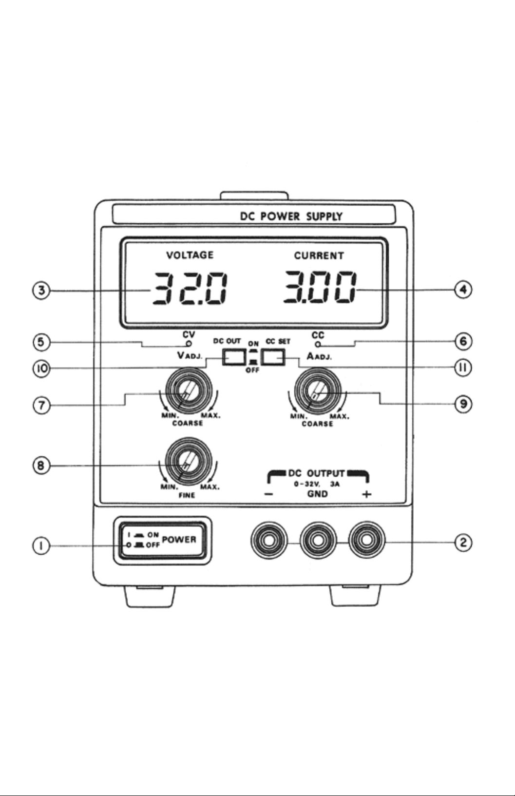
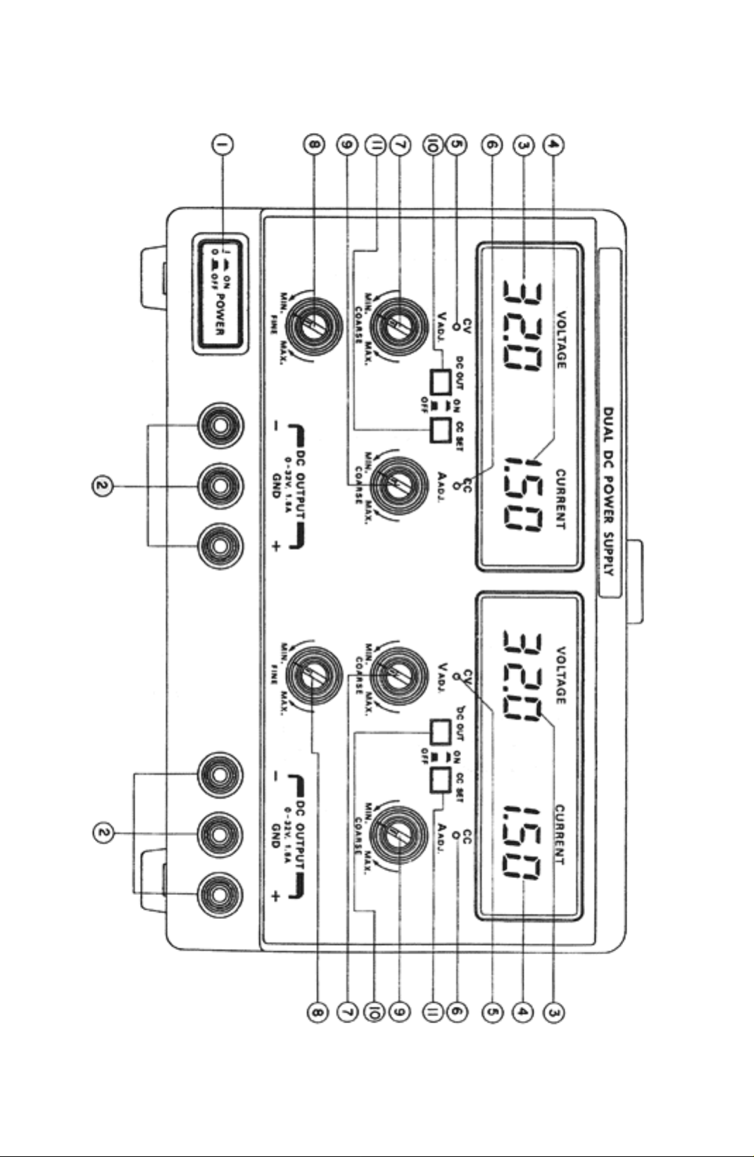
CONTROLS AND INDICATORS
①. POWER SWITCH: on/off switch.
②. OUTPUT TERMINAL: positive polarity (+) is red, negative polarity (-) is black, earth and
chassis ground is green.
③. DIGITAL VOLT METER: indicates the output voltage.
④. DIGITAL CURRENT METER: indicates the output current.
⑤. CV LAMP: lights when the power turn on and constant voltage operation.
⑥. CC LAMP: lights when this unit in constant current operation.
⑦. VOLT ADJ (COARSE) KNOB: for the coarse adjustment of the outpu t voltage.
⑧. VOLT ADJ (FINE) KNOB: for the fine adjustm ent of the ou tput vo ltage.
⑨. AMP ADJ KNOB: for the adjust ment of the output curr ent.
⑩ . DC OUTPUT SWITCH: on/off swich for the DC OUTPUT.
⑪. output terminal shorting or various loads, and CC SET SWITCH: current limiting set-up without
provide current limiting value preview faclity.
⑫. IND EPE ND EN T/ TR AC KI NG SW IT CH( TR IP LE ON LY ): Covering from independent appl ying of
S1 and S2 outputs to a serial connect. In tracking mode, because (-) of S2 and (+) of S1 are internally
connected, it is output inbetween (+) of S2 and (-) of S1. In case short pins are used inbetween (-)
terminal and ground, eliminate short pins from output terminals of S1 and S2.
Page 6
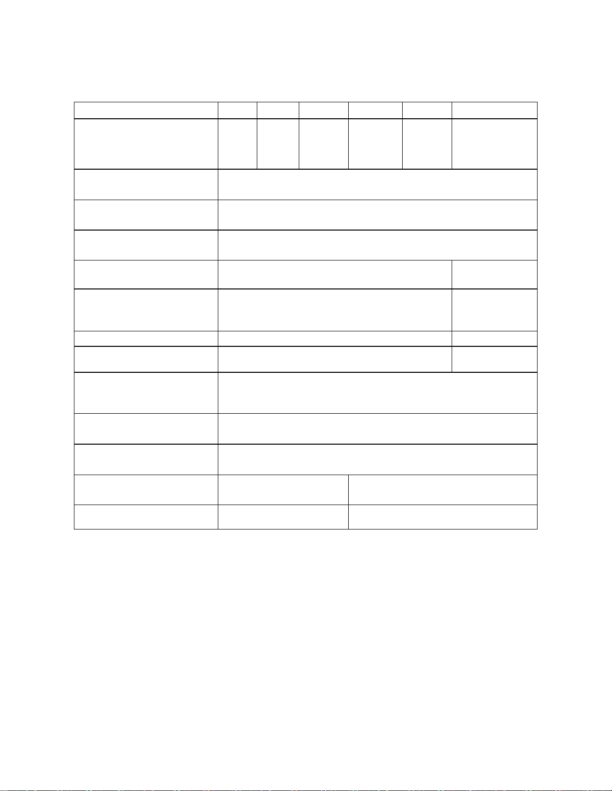
2. SPECIFICATION
MODEL 3003 3005 3006 3015 3032 3033
Output DC voltage
Output DC current
Load Regulation (Load Effect) ≤ 0.02% + 2mV
Line Regulation (Source Effect) ≤ 0.02% + 2mV
Ripple & Noise V, A ≤ 0.2mV(rms), 4mV(p-p)
Tracking Error ± (0.5% rdg + 1dgt)
0-30V
0-3A
≤ 0.05% + 5mA
≤ 0.05% + 0.25mA
≤ 2mA(rms), 10mA(p-p)
0-30V
0-5A
0-60V
0-1.5A
0-30V
0-1.5A
DUAL
0-30V
0 - 3A
DUAL
0 - 30V
0 - 1.5A
DUAL
5V, 5A FIXED
Fixed 5V, 5A
Output V, A
Ripple & Noise 2mV (rms)
Line & Load Regulation 0.1% ± 5mV
Digital Display
V, A, Accuracy
Temperature V
Coefficient A
Temperature Range 0 to 35 °C for rated output.
Dimension (mm)
W x H x D
Weight (kg) 5 kg 7.5 kg
5V ± 2.5%
5A ± 2.5%
3 dgts
3 dgts
± (0.5% rdg+ldgt)
≤ 0.05%+2mV/°C
≤ 0.1% + 2mA/°C
derate current 1% per degree C between 35 - 40°C.
124 x 160 x 326 234 x 160 x 326
Page 7

3. OPERATION
WARNING: Before connecting line power to your power supply, make sure that the AC input voltage is correct for
your power source.
TURN-ON CHECKOUT PROCEDURE.
a) Turn A-adj control fully counter clockwise.
b) Set AC power switch push to on position, digital display and CV lamp should light.
c) Turn VOLTAGE controls fully counter clockwise to ensure that output decreases to OV dc then fully
clockwise to ensure that output voltage increase to the maximum output voltage.
d) While depressing CC SET push button, turn the CURRENT control fully counter clockwise and then fully
clockwise to ensure that the current limit value can be set from zero to maximum rated value.
e) Connect load to output terminals.
CONSTANT VOLTAGE OPERATION
To set up a power supply for a constant voltage operation, proceed as follows:
a) Turn on power supply and adjust V-adj control for desired output voltage (ou tput terminals open). CV lamp
should light.
b) While depressing CC SET push button, adjust A-adj control for maximum output current allowable (current
limit). During actral operation, if a load change causes the current limit to be exceede d, the power supply will
automatically crossover to constant current mode and output voltage will drop proportion ately.
c) Push-on DC OUT push button switch for DC voltage output.
Page 8

CONSTANT CURRENT OPERATION
To set up a power supply for a constant current operation, proceed as follows:
a) Turn A-adj control fully counter clockwise to ensure that output decreases to 0 A, and then on power supply.
b) Adjust V-adj control (no load connected) for maximum output voltage allowable(voltage limit), as
determined by load conditions. During actual operation, if a load change causes the voltage limit to be
exceeded, the power supply will automatically crossover to constant voltage operation at the preset voltage
limit and output current will drop proportionately.
c) Adjust A-adj control for desired output current while depressing CC SET button.
d) Push-on DC OUT push button switch for DC voltage output .
CONNECTING LOADS
The output of the supply is isolated from earth ground. Either output terminal may be grounded or the output can be
floated up to 240 volts off ground.
TRACKING OPERATION (MODEL 3033 ONLY)
To select a tracking operation output as follows:
a) Set independent and tracking select switch to tracking position.
b) Depressing CC SET push button switch and adjust A-adj control of the each for maximum output current
allowable(current limit), as determined by load conditions.
c) Adjust V-adj controls (COARSE, FINE) of the MASTER for desired output voltage. This time, V-adj
controls (COARSE and FINE) of the SLAVE should be set on maximum.
d) Connect load using the negative (black) terminal of the SLAVE supply and the positive(red) terminal of the
MASTER supply.
e) Push DC OUT switch of both.
Page 9

4. MAINTENANCE
WARNING: The following instructions are f or use by q uali fi ed per s on nel onl y . To avoi d el ect rical shoc k, d o not
perform any servicing other then contained in the operating instructions unless you are qualified to do so.
Fuse Replacement
If the AC fuse blows, the CV or CC lamp will not light and the power supply will not operate. If the DC fuse blows, the
CV or CC lamp and digital display is light but DC OUTPUT will not operate. The fuse should not normally open
unless a problem has developed in the unit. Try to determine and correct the cause of the blown fuse, the n replace only
with a fuse of the correct rating and type.
The fuse is located on the rear panel.
Line Voltage Conversion
The primary winding of the p ower transforme r is tapped to perm it operation from 115,230 VAC, 50/6 0 Hz line voltage.
Conversion from one line voltage to anther is done by AC select switch on the rear panel.
The line voltage to switch the unit was factory setted. To convert to a different line voltage, perform the following
procedure;
a) Make sure the power cord is unplugged.
b) Change the AC selects switch to the desired line voltage position.
c) A change in line voltage may also require a corresponding change of fuse value. Install the correct fuse value as
listed on rear panel.
Page 10

5. CALIBRATION ADJUSTMENT
ADJUSTMENT OF THE RATING VOLTAGE.
a) Connect digital multimeter across output terminals of supply and set the DC volt position.
b) Turn on supply and push on DC OUT push button switch.
c) Adjust voltage controls (COARSE, FINE) fully clockwise.
d) Adjust S203 for a reading of rate volts x 1.05 on the digital multimeter.
e) Adjust S401 until digital multimeter reads exactly maximum rated
output voltage.
f) Push-off DC OUT push button switch and adjust S202 until front panel meter reads exactly digital
multimeter reading.
ADJUSTMENT OF THE RATING CURRENT
a) Connect load resistor and digital multimeter with series and set the range to DC 20 Amp position.
b) Turn on supply.
c) Adjust voltage controls and current control to minimum (fully counter-clockwise).
d) Adjust S201 for reading of 0 Amps on the digital multimeter.
e) Adjust voltage con trols and curr en t contro l to maximu m (f ully c lock-wise).
f) Adjust S501 until front panel meter reads exactly digital multimeter reading.
g) Push on CC SET push button switch.
h) Adjust S204 until digital multimeter exactly the maximum rated output current.
 Loading...