

Instructions for the following series products:
LADDER CLIMBING CABLE SLEEVE
Model Numbers: See Figure 1
User Instruction Manual Cabloc Detachable Cable Sleeve
This manual is intended to be used as part of an employee training program as recommended by OSHA.
WARNING: These instructions must be provided to the user and
this
equipment must read and understand these instructions before
installer of this equipment. The user and installer of
use or installation. Follow the manufacturer’s
instructions for other safety equipment used with this system. Follow these instructions for proper use,
inspection, and
maintenance of this equipment. This product is intended to be
used as a part of a complete Cabloc
ladder safety system. Alterations, substitutions, or misuse of this equipment, or failure to follow instructions,
may result in serious injury or death.
IMPORTANT: If you have questions on the installation, use, maintenance, or suitability of this equipment for
your application, contact PROTECTA.
IMPORTANT: Before using this equipment, record the product
identifi cation information from the installation and
service label in the “Inspection and Maintenance Log” at the back of this manual.
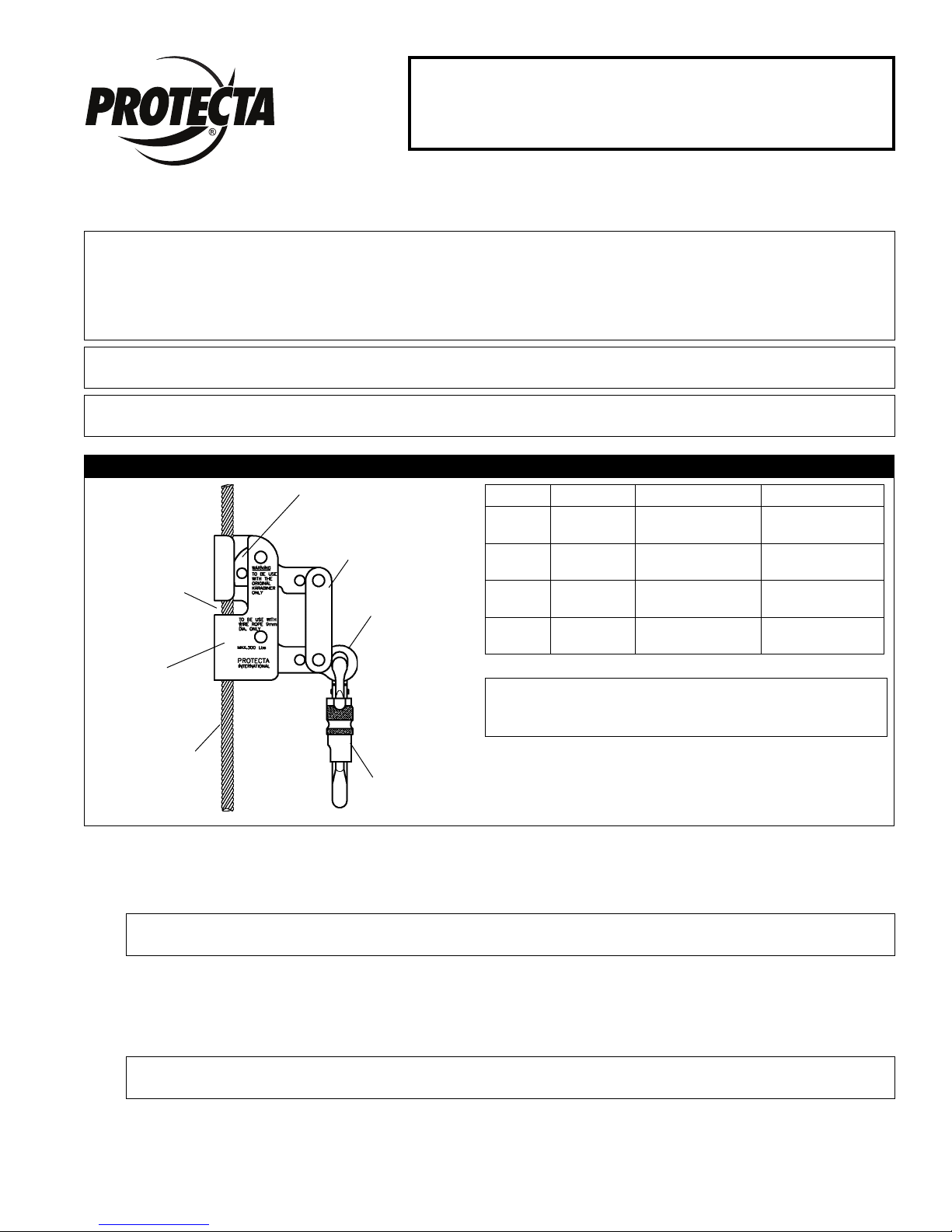
Figure 1 - Cabloc Detachable Cable Sleeves
Cable
Installation
Slot
Sleeve
Body
Cable Shoe
Brake Lever
Attachment
Point
Model Cable Dia. Safety Standard Anti-Inversion
AC350A
AC351A
AC350C
AC351C
5/16”
(8 mm)
3/8 “
(9.5 mm)
5/16”
(8 mm)
3/8 “
(9.5 mm)
ANSI A14.3
ANSI A14.3
CSA Z259.2.1
CSA Z259.2.1
√
√
7 X 19 CABLE ONLY: Cabloc Cable Sleeves shall only
be used on 7 x 19 constructed cable of the diameters
specifi ed above.
7 x 19 Constructed
Steel Cable
(Carrier Cable)
Carabiner
1.0 APPLICATIONS
1.1 PURPOSE: The Cabloc detachable cable sleeve is designed to arrest the fall of personnel while climbing a
fi xed ladder. The detachable cable sleeve is not intended to be used for material handling.
NOTE: The installer and user must ensure the ladder meets all applicable local, state, and federal
standards, including ANSI A14.3.
1.2 LIMITATIONS: Cabloc detachable cable sleeves must be used with a PROTECTA approved ladder safety
system. Use only the Cabloc Sleeve model specifi ed in Figure 1 for you applicable cable diameter and safety
standard(s). The Cabloc cable sleeve must be directly connected to an approved full body harness with the
carabiner supplied with the sleeve (see Figure 1). Do not use connection devices other than the supplied
carabiner. Do not add additional connectors or lanyards between the user and the cable sleeve.
NOTE: ANSI A14.3 and OSHA 1926.1053 states that the length of connection between the carrier cable
and
attachment point on the full body harness must not exceed 9 in. (0.2 m) in Canada per CSA Z 259.2.1-98.
1.3 Refer to applicable local, state, and federal (OSHA) requirements governing this
information on ladder safety systems and associated components, including OSHA 1910.27.
equipment for more
© Copyright 2012, Capital SafetyForm No: 5902216 Rev: F

2.0 SYSTEM REQUIREMENTS
2.1 COMPATIBILITY OF COMPONENTS AND SUBSYSTEMS: This equipment is designed for use with
PROTECTA approved components and subsystems. The use of non-approved components and subsystems
may jeopardize compatibility of equipment, and could affect the safety and reliability of the complete
system. Contact Capital Safety if you have questions about compatibility of equipment.
WARNING: Before using a Cabloc Ladder System in combination with a climb assist system, consult
the climb assist system manufacturer’s instructions for any restrictions or limitations concerning
simultaneous use of these systems. Capital Safety has found that some connection combinations may
interfere with proper operation of the Cabloc Detachable Sleeve and may result in failure to arrest a fall.
Avoid connecting the sleeve used on the Cabloc Ladder System into the same harness connection D-ring
as is occupied by the climb assist system. Ensure that movement of the arm of the Cabloc sleeve is not
restricted or interfered with by the climb assist system or its connectors. Failure to heed this warning may
result in serious injury or death.
2.2 COMPATIBILITY OF CONNECTORS: Connectors used with this system (hooks, carabiners, D-rings) must
be capable of supporting a minimum of 5,000 lbs. Use caution to assure compatibility of hooks and the
connection point. Non-compatible connectors may unintentionally disengage (roll-out). Connectors must be
compatible in size, shape, and strength. All connectors used must be self closing/self locking connectors.
3.0 OPERATION AND USE
3.1 BEFORE EACH USE: Inspect the ladder climbing system according to the manufacturer’s instructions. Do
not climb a structure that is not in good condition. Verify from the label markings that the system has been
formally inspected within the last year. Do not use a defective or improperly maintained Cabloc system.
Inspect the detachable cable sleeve according to section 5.0. Inspect your full body harness according to the
manufacturer’s instructions.
3.2 CONNECTING THE CABLOC CABLE SLEEVE TO THE CARRIER CABLE:
WARNING: The Cabloc sleeve must only be used on a vertical cable system. Do not use the cable on
angled or horizontal cable systems as the sleeve may no lock properly on the cable. In situations where a
fall hazard exists, use a back-up fall arrest system, such as a lanyard, to protect against a fall.
Step 1. Ensure the sleeve is correctly positioned relative to the carrier cable. The “up” arrow on the sleeve
must be pointing to the ascending direction. See Figure 2.
IMPORTANT: Never install the sleeve upside down on the cable.
Step 2. Remove the carabiner and pivot the handle to its full upright position. This will draw back the
cable shoe to allow insertion of the carrier cable into the sleeve housing. The sleeve design does
not allow the sleeve to be installed or removed while the carabiner is attached to the handle.
Step 3. Rotate the top of the sleeve to the right until the sleeve body is horizontal. Position the sleeve
so that the cable slides all the way into the cable installation slot. Rotate the sleeve back into a
vertical position so that the cable is captive in the cable slot.
Step 4. Allow the handle to return to its operating position. This will allow the cable shoe to contact the
cable and lock the cable in the sleeve body. Reattach the supplied Carabiner to the attachment
point of the Cabloc sleeve.
Figure 2 - Installation
Step 1 Step 2 Step 3 Step 4
2

3.3 CONNECTING THE CABLOC SLEEVE TO THE HARNESS: Use only the supplied carabiner to connect the
Cabloc to the harness. Do not substitute with other connectors. Do not use other connecting devices, such
as; lanyards, chain, links, or clevis. These types of connectors do not meet PROTECTA requirements. OSHA
and ANSI A14.3 prohibits connections between the carrier cable and the harness that exceed nine inches in
length. When connecting ensure the gate on the carabiner is closed and locked. CSA Z259.2.1-98 prohibits
the use of connectors longer than 0.2m in length.
3.4 CLIMBING ON THE SYSTEM:
Step 1. Don the appropriate full body harness according to the manufacturer’s instructions.
Step 2. Attach the Cabloc cable sleeve to the carrier cable (see section 3.2).
Step 3. Connect the Cabloc cable sleeve to the attachment point on the full body harness.
Step 4. To ascend, climb up the ladder normally. The detachable cable sleeve will follow the climber.
The carrier cable will snap out of the cable guides as the climber passes the guides. Reconnect
the carrier cable to the cable guide after passing each guide. Do not remove detachable cable
sleeve from carrier cable to pass cable guides. Use caution when climbing. Avoid carrying tools or
equipment that do not allow your hands to be free for climbing. Ensure items carried are secure
to avoid dropping on climbers below. Climb within your ability. Long climbs may require several
rest stops during ascent or descent to avoid exhaustion. Avoid climbing in high winds or severe
weather whenever possible.
Step 5. To descend, climb down smoothly in a normal position. Allow the detachable cable sleeve to
lead the climber down. Climbing down out of position (leaning back excessively) will cause the
detachable cable sleeve to lock on the carrier cable. If the detachable cable sleeve locks, move
upward slightly to release, then continue down the ladder.
4.0 TRAINING
4.1 TRAINING: It is the responsibility of the user and purchaser of this equipment to assure they are familiar
with these instructions, operating characteristics, application limits, and the consequences of improper use
of this equipment. Users and purchasers of this equipment must be trained in the correct care and use of
this equipment.
IMPORTANT: Training must be conducted without exposing the user to a fall hazard. Training should be
repeated on a periodic basis.
5.0 INSPECTION
5.1 FREQUENCY:
• Before Each Use: Visually inspect the detachable cable sleeve with the Cabloc installation according to
section 5.2 and 5.3. Inspect other system components according to manufacturer’s instructions.
• Formal Inspection: A formal inspection of the detachable cable sleeve must be performed at least
annually by a competent person1 other than the user.
• After a Fall: If a fall occurs with the detachable cable sleeve or on the Cabloc system a formal
inspection of the entire system must be performed by a competent person other than the user. See
sections 5.2 and 5.3. Record the inspection results in the “Inspection and Maintenance Log”.
5.2 INSPECTION GUIDELINES FOR CABLOC LADDER SAFETY SLEEVE:
• Inspect: the brake lever and cable shoe for bends, cracks, and deformation. Inspect the connection
point for wear or distortion. Check all surfaces for corrosion. All fasteners and rivets must be securely
attached. Operation of the brake lever and cable shoe must be free and smooth. Springs must be secure
and of suffi cient strength to pull the brake lever down. See Figure 1.
• Inspect: the sleeve body for wear on the inside where the cable passes through.
• Inspect Markings: All markings must be present and completely legible. See Figure 3.
• In Canada: ensure that the anti-inversion device is operational by turning the cable sleeve upside
down and trying to operate the brake lever. If the lever operates up and down in the inverted position,
the anti-inversion device is defective and the sleeve must be removed from service and destroyed or
returned to Protecta for repair.
5.3 IF INSPECTION REVEALS AN UNSAFE OR DEFECTIVE CONDITION: Remove the ladder safety system
or detachable cable sleeve from service and destroy or contact an authorized service center for repair.
1 Competent Person: An individual designated by the employer to be responsible for the immediate supervision, implementation, and monitoring of the
employer’s managed fall protection program who, through training and knowledge, is capable of identifying, evaluating, and addressing existing and potential fall
hazards, and who has the employer’s authority to take prompt corrective action with regard to such hazards.
3

Figure 3 - Markings
B
A
C
AC350A
A B C
AC351A
A B
AC350C
A B C
AC351C
A B C
4

6.0 MAINTENANCE, SERVICE, AND STORAGE
6.1 The Cabloc sleeve may be cleaned using commercial parts cleaning solvents and rinsed with warm, soapy
water. Light machine oil may be applied to moving parts if required. Do not use excessive oil, or allow oil to
contact cable clamping surfaces. Store the detachable cable sleeve in a cool, dry, clean environment, out of
direct sunlight. Avoid areas where chemical vapors exits. Thoroughly inspect sleeve after extended storage.
6.2 ADDITIONAL MAINTENANCE and servicing procedures must be completed by an authorized service
center. Authorization must be in writing.
7.0 SPECIFICATIONS
DETACHABLE SLEEVE:
• Material: Stainless Steel
• Breaking Strength: 5,500 lbs (24.5 kN)
• Net Weight (with Carabiner): 1.54 lbs (.70 kg)
• Cable: Galvanized Steel or Stainless Steel 7 x 19 Constructed Cable (See Figure 1 for required
diameter)
CARABINER:
• Material: High strength steel
• Breaking Strength: 5,500 lbs (24.5 kN)
5

Warranty to End User: D B Industries, Inc., dba CAPITAL SAFETY USA (“CAPITAL SAFETY”)
LIMITED LIFETIME WARRANTY
warrants to the original end user (“End User”) that its products are free from defects in materials and
workmanship under normal use and service. This warranty extends for the lifetime of the product
from the date the product is purchased by the End User, in new and unused condition, from a CAPITAL
SAFETY authorized distributor. CAPITAL SAFETY’S entire liability to End User and End User’s exclusive
remedy under this warranty is limited to the repair or replacement in kind of any defective product
within its lifetime (as CAPITAL SAFETY in its sole discretion determines and deems appropriate). No oral
or written information or advice given by CAPITAL SAFETY, its distributors, directors, offi cers, agents
or employees shall create any different or additional warranties or in any way increase the scope of
this warranty. CAPITAL SAFETY will not accept liability for defects that are the result of product abuse,
misuse, alteration or modifi cation, or for defects that are due to a failure to install, maintain, or use the
product in accordance with the manufacturer’s instructions.
CAPITAL SAFETY’S WARRANTY APPLIES ONLY TO THE END USER. THIS WARRANTY IS THE ONLY
WARRANTY APPLICABLE TO OUR PRODUCTS AND IS IN LIEU OF ALL OTHER WARRANTIES AND
LIABILITIES, EXPRESSED OR IMPLIED. CAPITAL SAFETY EXPRESSLY EXCLUDES AND DISCLAIMS
ANY IMPLIED WARRANTIES OF MERCHANTABILITY OR FITNESS FOR A PARTICULAR PURPOSE, AND
SHALL NOT BE LIABLE FOR INCIDENTAL, PUNITIVE OR CONSEQUENTIAL DAMAGES OF ANY NATURE,
INCLUDING WITHOUT LIMITATION, LOST PROFITS, REVENUES, OR PRODUCTIVITY, OR FOR BODILY
INJURY OR DEATH OR LOSS OR DAMAGE TO PROPERTY, UNDER ANY THEORY OF LIABILITY, INCLUDING
WITHOUT LIMITATION, CONTRACT, WARRANTY, STRICT LIABILITY, TORT (INCLUDING NEGLIGENCE) OR
OTHER LEGAL OR EQUITABLE THEORY.
Garantie offerte à l’utilisateur fi nal : D B Industries, Inc., dba CAPITAL SAFETY USA (« CAPITAL SAFETY »)
GARANTIE LIMITÉE SUR LA DURÉE DE VIE
garantit à l’utilisateur fi nal d’origine (« Utilisateur fi nal ») que les produits sont libres de tout défaut matériel et de
fabrication dans des conditions normales d’utilisation et de service. Cette garantie couvre toute la durée de vie du
produit, de sa date d’achat à l’état neuf et inutilisé par l’utilisateur auprès d’un distributeur agréé CAPITAL SAFETY.
La responsabilité intégrale de Capital Safety et le seul recours du Client dans le cadre de cette garantie se limitent
à la réparation ou le remplacement en nature des produits défectueux pendant leur durée de vie (à la seule
discrétion de Capital Safety et selon ce qu’elle juge approprié). Aucun renseignement ou avis oral ou écrit fourni par
CAPITAL SAFETY, ses détaillants, administrateurs, cadres, distributeurs, mandataires ou employés ne représentera
une garantie ou n’augmentera de quelque manière la portée de la présente garantie limitée. CAPITAL SAFETY
n’accepte aucune responsabilité pour les défauts causés par un abus, une utilisation abusive, une altération ou une
modifi cation, ou pour les défauts causés par le non-respect des instructions du fabricant relatives à l’installation,
à l’entretien ou à l’utilisation du produit.
CETTE GARANTIE CAPITAL SAFETY S’APPLIQUE UNIQUEMENT À L’UTILISATEUR FINAL. ELLE EST LA SEULE
GARANTIE APPLICABLE À NOS PRODUITS. ELLE EXCLUT TOUTE AUTRE GARANTIE EXPRESSE OU IMPLICITE.
CAPITAL SAFETY EXCLUT EXPLICITEMENT ET DÉCLINE TOUTE GARANTIE IMPLICITE DE MISE EN MARCHÉ ET
D’ADAPTATION À DES FINS PARTICULIÈRES, ET NE SERA RESPONSABLE POUR AUCUN DOMMAGE-INTÉRÊT
DIRECT OU INDIRECT, CORRÉLATIF OU ACCESSOIRE DE TOUTE NATURE Y COMPRIS ET DE MANIÈRE NON
LIMITATIVE, LES PERTES DE PROFITS, LES REVENUS OU LA PRODUCTIVITÉ, LES BLESSURES CORPORELLES,
VOIRE LA MORT OU DOMMAGES À LA PROPRIÉTÉ, DANS LE CADRE DE TOUTE THÉORIE DE RESPONSABILITÉ, Y
COMPRIS ET DE MANIÈRE NON LIMITATIVE UN CONTRAT, UNE GARANTIE, UNE RESPONSABILITÉ (Y COMPRIS LA
NÉGLIGENCE) OU TOUTE AUTRE THÉORIE LÉGALE OU ÉQUITABLE.

INSPECTION AND MAINTENANCE LOG
SERIAL NUMBER:
MODEL NUMBER:
DATE PURCHASED: DATE OF FIRST USE:
INSPECTION DATE INSPECTION ITEMS
NOTED
Approved By:
Approved By:
Approved By:
Approved By:
Approved By:
Approved By:
Approved By:
Approved By:
CORRECTIVE ACTION MAINTENANCE
PERFORMED
Approved By:
Approved By:
Approved By:
Approved By:
Approved By:
Approved By:
Approved By:
Approved By:
Approved By:
Approved By:

A Capital Safety Company
CSG USA & Latin America
3833 SALA Way
Red Wing, MN 55066-5005
Toll Free: 800.328.6146
Phone: 651.388.8282
Fax: 651.388.5065
solutions@capitalsafety.com
CSG EMEA
(Europe, Middle East, Africa)
Le Broc Center
Z.I. 1ère Avenue
5600 M B.P. 15 06511
Carros
Le Broc Cedex
France
Phone: + 33 4 97 10 00 10
Fax: + 33 4 93 08 79 70
information@capitalsafety.com
CSG Canada
260 Export Boulevard
Mississauga, ON L5S 1Y9
Phone: 905.795.9333
Toll-Free: 800.387.7484
Fax: 888.387.7484
info.ca@capitalsafety.com
CSG Australia & New Zealand
95 Derby Street
Silverwater
Sydney NSW 2128
AUSTRALIA
Phone: +(61) 2 8753 7600
Toll-Free : 1 800 245 002 (AUS)
Toll-Free : 0800 212 505 (NZ)
Fax: +(61) 2 87853 7603
sales@capitalsafety.com.au
www.capitalsafety.com
ISO
9001
Certificate No. FM 39709
CSG Northern Europe
5a Merse Road
North Moons, Moat
Reditch, Worcestershire, UK
B98 9HL
Phone: + 44 (0)1527 548 000
Fax: + 44 (0)1527 591 000
csgne@capitalsafety.com
CSG Asia
Singapore:
16S, Enterprise Road
Singapore 627666
Phone: +65 - 65587758
Fax: +65 - 65587058
inquiry@capitalsafety.com
Shanghai:
Rm 1406, China Venturetech Plaza
819 Nan Jing Xi Rd,
Shanghai 200041, P R China
Phone: +86 21 62539050
Fax: +86 21 62539060
 Loading...