

Page 1
page 1
PNA 4500
Vectorial
Performance Network Analyser
Quick Guide
Page 2

page 2
Table of contents
Explanation of the controls 3
General information 4
Scope of delivery 4
Warnings 5
Power supply: mains / battery mode 6
Switch on the PNA 4500 7
Explanation of the one-touch keys 7
Easy handling with Quick Start Wizard 8
Use as vector-network analyser 9
Use as cable analyser (DTF) 13
Use as power detector (power measurement) 17
Option: Measurement of GPS antennas 20
Review of further optional measuring possibilities 23
Setting of keyboard language 24
Installation of software updates 26
Specifications 27
Page 3
page 3
PNA 4500
Explanation of controls and connections
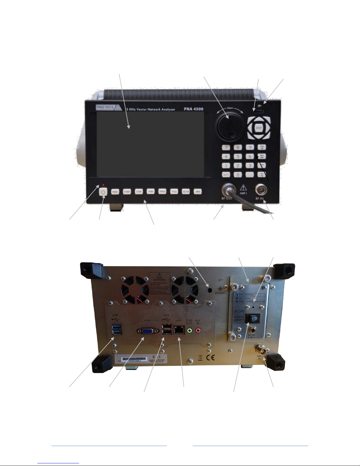
7“ Touch Screen rotary /push combi button control Windows button USB port
Status LED on/off one-touch keys RF OUT connection RF IN connection
port for battery Status-LED
GPS antenna compartment for battery charge
2 x USB 3.0 VGA port 2 x USB 2.0 LAN : remote main switch for input for 10 MHz
f. ext. monitor power supply reference signal
- battery charging
- 230 V AC mode
Page 4

page 4
General information
The PNA 4500 is a vector network analyser with a built-in Windows PC. It can be operated either
stationary with the 230 V AC power supply unit or mobile with the battery compartment.
The PNA 4500 can be operated either directly or remotely. No special software is required for remote
operation. Operation is browser-based. The browser-based terminal is connected via the back-side
LAN port. If a mobile WLAN router is connected to this port, the PNA 4500 can also be remotecontrolled via a web browser on a smartphone, tablet etc.
The screen of the PNA 4500 is a touch-sensitive touch screen monitor. Operation is carried out via
dynamic buttons on the screen, via direct selection buttons below the screen, via a 10-keys keyboard
as well as with the rotary / push button control to the right of the screen. Alternatively, a keyboard, a
mouse and printer can be connected via the back USB ports.
Note: Some of the functions described are not included in the standard scope of the Network
Analyser and require optional accessories or optional software.
Scope of delivery
Included in the delivery:
- Network Analyser PRO-TECS PNA 4500
- 230V AC charger
- Battery compartment with charging electronics
- calibration certificate
- transport case
Optional accessories:
Hardware:
- Additional battery compartment
- Additional 230 V AC charger
- Calibration kit standard, consisting of Open, Short and 50 Ohm as well as N-N calibration cables
- Calibration kit extended, consisting of N-Open, N-Short and N-50 Ohm as well as N-N calibration
cables as well as SMA-Open, SMA-Short and SMA-50 Ohm, SMA-SMA calibration cable as well as 2 x
N-SMA charger
- Power measuring head for the performance measurement of analogue and digital radios
- Measuring head for spectrum analysis
- Integrated GPS module
Software:
App - GPS Antenna measurement
App - field strength measurement + GPS position memory including log file creation for display in
Google Maps
App - Panorama measurement
App - Antenna radiation measurement
App - Signal runtime measurement (Group Delay)
App - DTF cable analysis (Distance to fault)
Page 5
page 5
Warnings:
In order to achieve precise measurement results, the PNA 4500 is equipped with high-quality,
broadband measurement detectors. Please note that these sensitive detectors can be damaged or
destroyed if they are charged with excessive energy.
Avoid static discharges via these measuring connections, which can occur when connecting test
specimens to the RF IN or RF OUT connector. If necessary, ensure that static charges are dissipated,
e.g. by attaching a grounded ESD antistatic wristband.
The detectors measure existing signals in a broadband spectrum (100 kHz - 3 GHz), even if the display
in the measurement diagram is reduced to the desired range. As a result, large signals exceeding
certain maximum values can lead to falsified measurement results and possibly to damage of the
measurement detectors.
ATTENTION: In order to measure the transmitter output power of radio devices, these must only be
connected to the external power detector.
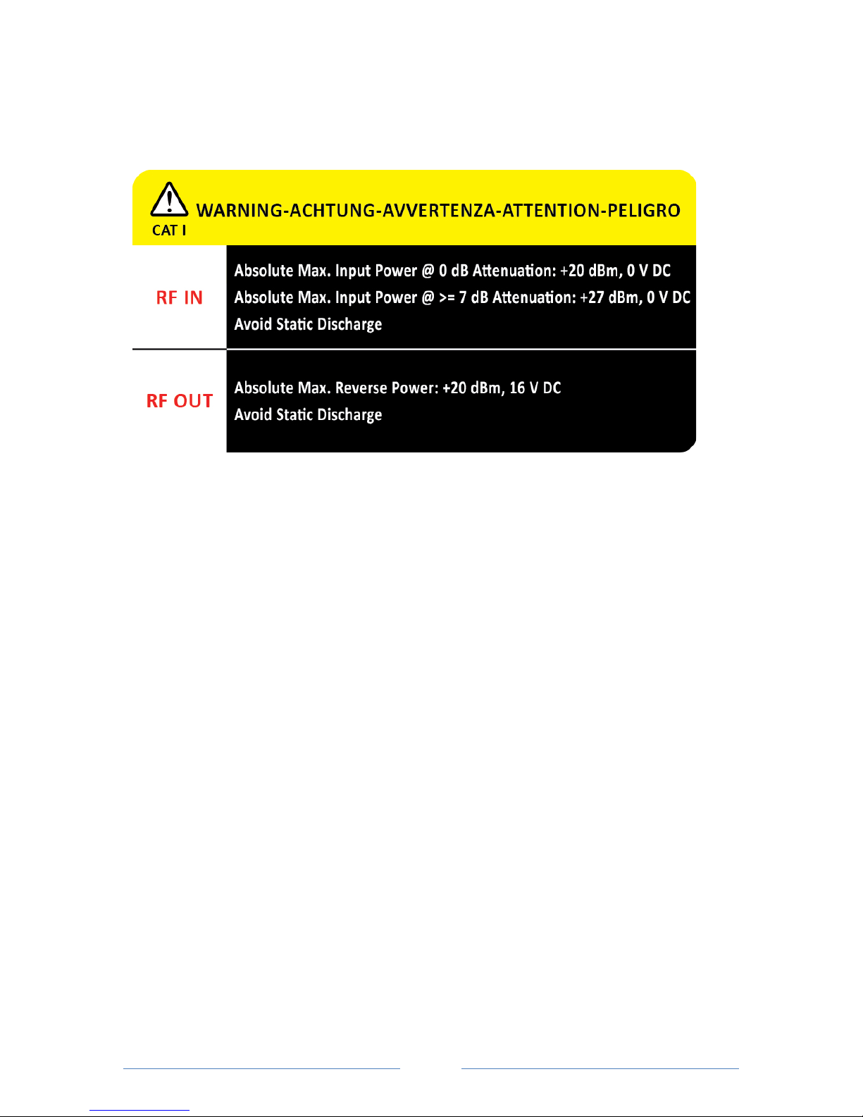
The maximum levels of the measuring connections are:
RF OUT (reflection measurement):
Max. return power: + 20 dBm (= 100mW), 16V DC
RF IN (input level measurement):
Max. input power:
- At 0 dB attenuation: +20 dBm (= 100 mW), 0 V DC
- At> 7 dB attenuation: +27 dBm (= 500 mW), 0 V DC
External detector (power measurement):
Max. transmission power: depending on the measuring head (typ. +20 to +43 dBm (100 mW to 20
Watt). See type plate.
Higher power measurements are possible with pre-connected attenuators.
Page 6
page 6
Operation of the PNA 4500:
1. Power supply :
The power supply for the PNA 4500 is either via the battery compartment or via the supplied 230 V
AC charger. Please note that the use of a different charger will void the warranty and may cause
serious consequential damages to the product.
The main switch on the back of the battery compartment has to be set to "1" to:
- use the PNA 4500 in mains operation and simultaneously charge the battery.
- charge the battery pack in the compartment when it is not in the PNA 4500.
The status LED of the battery pack indicates the current charging status:
- red flashing = battery is charging
- red = fault
- green = battery is fully charged
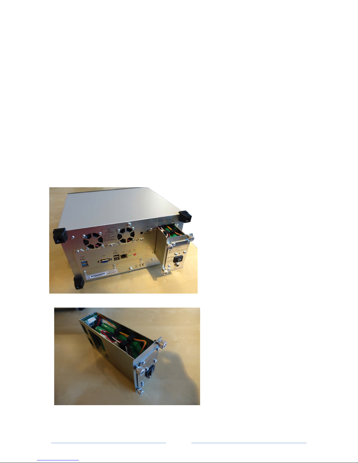
The battery compartment is accessible
on the back of the device and can be
replaced from the outside. To do this,
the three knurled screws must be
loosened, then the compartment can be
pulled out.
When inserting the battery
compartment, make sure that the
contact strip is positioned correctly
before tightening the three knurled
screws.
The battery compartment contains the
battery block (4.4 Ah, NiMh) as well as
the charging electronics. Thus, an
optional additional battery
compartment can be loaded separately
from the PNA 4500. The 230 V AC
charger is to be used for charging.
Page 7

page 7
2. Switch on the PNA 4500
Press the on/off switch at the bottom left until the status LED that is placed over it starts to flash.
The PC starts the Windows operating system and configures the PNA 4500 software.
Note: If the backside main switch is set to "0", the power is supplied via the battery compartment.
For operation via the 230 V AC charger, turn the main switch to "1".
3. Prepare the PNA 4500 for the desired measurement
1. Variant: Setup using the one-touch keys
MODE:
Choice of the operating mode (vector analyser, DTF cable measurement, power measurement and if
needed optional measuring possibilities)
START:
Input of the start frequency of the desired measuring range
STOP:
Input of the end frequency of the desired measuring range
PWR (Power):
Input of the power generated by the signal generator, which is available at the RF OUT measuring
socket
TRACE:
Input of parameters for the display of the measuring trace
FILE:
Retrieve and save device configurations as pre-sets (PRESET)
Save and generate measurement documentation
SETUP:
Input of the device configuration and start of the calibration process
MKR (Marker):
Switch on and off as well as place max. 8 marker frequencies
Note: The functions within the one-touch keys differ depending on the operating mode.
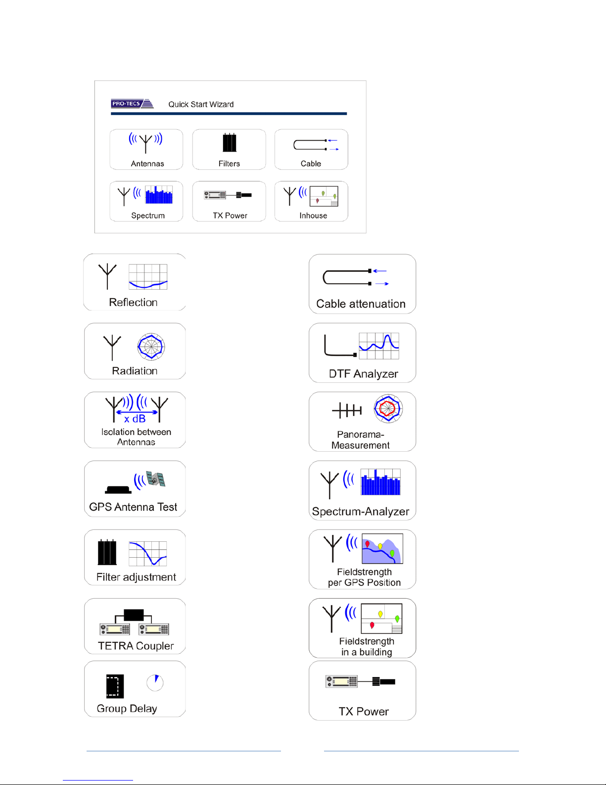
2. Variant : Setup using the Quick Start Wizard
The Quick Start wizard guides you directly to the target with self-explanatory apps.
Only relevant values are queried and then the PNA 4500 is completely ready for measurement. In
this way measurement errors are considerably reduced.
Note:
The prerequisite is that the necessary measurement options have been purchased and have been
activated in the PNA 4500.
Page 8
page 8
Setup of the PNA 4500 using the Quick Start Wizard
Quick Start Wizard:
Press the rotating knob,
alternatively via the "FILE" and
"Setup Assistant on" keys.
Then tap the desired app for the
required measurement and
follow the following sequence
intuitively.
All device settings are then made
automatically.
App :
Antenna adjustment
SWR, return loss,
Smith diagram,
phase
App :
Cable attenuation
Measure attenuation and
ripple of coaxial cables
App :
Antenna radiation
Measure the radiation
of antennas, radiation
diagrams
App :
DTF cable analysis
Distance to fault
Measurement of cable
length and fault ocalisation
App :
Antenna decoupling
Measure decoupling
between two antennas
App :
Panoramic measurement
Automated measurement
with LAC decoding and
rotor control
App :
GPS Antenna test
Test of GPS antennas
for an adjustable period
of time
App :
Spectrum analysis
Measure a frequency
spectrum
App :
Easy calibration of
filters and system
components
App :
GPS Map
Measure the field strength
per position for display in
Google Maps
App :
TETRA coupler :
Measuring and
adjusting from TETRA
radio couplers
App :
Signal strength measurement in the building with
table generation, storage in
floor plan
App :
Runtime measurement
Measuring the signal
runtime (Group Delay)
App :
Power measurement
Measurement of analogue
and digital transmission
power
Page 9
page 9
Operation mode: VNA Vector Network Analyser
Short instructions for using the PNA 4500 as a network analyser (without Quick Start
Wizard):
1. Select the operating mode: MODE - VNA
2. Call the pre-set: FILE – Pre-set – Load – select and load pre-setting
3. Calibrate: SETUP - Calibration – calibrate S11 and/or S21
Ready to measure.
Save measurement: FILE - Save - Report - Print or save measurement report
Configuration of the PNA 4500 using the one-touch keys:
MODE :
Select the operation mode VNA Vector Network Analyser.
START :
Enter the start frequency of the desired measuring range.
STOP :
Enter the end frequency of the desired measuring range.
Note :
Also by entering a center frequency "Center Freq." and a frequency range "Freq.Span" the
frequency range can alternatively be set to "START Freq." and "STOP Freq.". With "Span min", the
minimum possible span (depending on the selected number of measuring points) is selected in
order to enable a measurement on a single frequency.
PWR :
(Power): The power generated by the signal generator. The max. power is -5 dBm.
TRACE :
Enter the parameters in order to display the measuring trace. Select one of the softkeys placed above
the measurement diagram for max. 4 measuring traces.
Note :
The following steps must be repeated or adjusted for each of the selected measuring traces.
Measure:
Select the measuring socket. (S11-RF OUT reflection measurement or S21-RF IN attenuation
measurement). Go back by pressing the "Back" softkey.
Format: Selection of desired display format:
- Log. Magnitude (dB return loss)
Page 10

page
10
- Phase (phase position)
- Smith Chart (Smith-diagram)
- SWR (standing wave ratio)
Scale: Setting of the scale:
The values are entered using the 10-keys keypad, by turning the rotary knob or by pressing the
"arrow up" or "arrow down" keys. Confirm with the "ENT" (ENTER) key.
- Ref. Level: Enter the value for the reference line
- Ref.Position: Selection of the position on which the reference line is placed in the diagram
(0-10)
- Scale : Enter the value to determine the steps the scale of measurement results should be
displayed with
- Autoscale : Automatic scaling by the analyser based on the measured values
- Default : Reset to factory setting
Data To Ref: Saves current measurement curve as a reference.
Display Mode: Selection of the measured values displayed on the screen:
- Data : Display of measurement data of the actual measurement
- Reference : Display of the saved reference measurement curve
- Data & Ref. : Simultaneous display of the current and the saved reference measurement
curve
- Data - Ref. : Display of measured values which lie below the reference measurement curve
Hide: Measuring trace is blanked. Softkey changes to "Show". Press the button again to display the
measuring trace again.
FILE :
Pre-set or save files:
- Preset : Pre-sets for frequently recurring measurements
o Load : Call saved pre-sets
A selection menu of the saved pre-sets appears. Select with "arrow up" or "arrow
down" keys, confirm with "Load".
o Save : Save a newly created device setting as default setting
A window for entering a filename for the new default appears. Input via an external
keyboard (connection via USB) or via the Windows screen keyboard, which can be
called whilst pressing "Show On Screen Keyboard".
- Save : Save measurements
o Print Screen: Create an image file of the measurement displayed on the screen. The
file is saved as a "*.png" file.
o Trace : Saves the measuring trace
o Report: Creation of a measurement report. This measurement report can optionally
be printed via a printer (connection via USB) or be saved as an Excel, PDF or Word
file.
SETUP :
Page 11

page
11
Set measurement parameters. The values can be changed using the rotary control or the "arrow up"
or "arrow down" keys.
- Filter BW: Setting of the filter bandwidth between 100 Hz and 150 KHz.
Reducing the bandwidth results in a longer duration of the measurement session.
- Point: Setting of the number of measuring points per measurement session. You can select
between 201, 401, 601, 801 and 1.001 measuring points.
- Time: Setup of time for a measurement (Sweep-Time).
- Calibration : Call up the calibration procedure
o S11 Calibration : Call up the calibration of the RF-OUT measurement detector :
1. Turn "Open" of the calibration kit onto the RF-OUT socket. Press the "Open" softkey
and wait for the calibration procedure.
2. Turn the “short circuit” of the calibration kit to the RF-OUT socket. Press the "Short"
softkey and wait for the calibration procedure.
3. Turn "50 Ohm Load/Absorber" of the calibration kit onto the RF-OUT socket. Press
the "Load" softkey and wait for the calibration procedure.
4. The "done" softkey now appears. Press this button to complete the calibration
procedure. The following will be displayed in green in the lower part: "S11 CAL".
o S21 Calibration: Call up the calibration of the RF-IN measurement detector:
1. Connect the measurement detectors "RF-OUT" and "RF-IN" with the calibration
cable.
2. Now press the "Through" softkey and wait for the calibration procedure.
3. The "done" softkey appears. Press this button to complete the calibration process.
The following will be displayed in green in the lower part: "S21 CAL".
Reset: Reset of the calibration
If the calibration is faulty (for example, the components of the calibration kit are mixed
up, etc.), press the "Reset" softkey and repeat the calibration procedure.
- SETUP 1 / 3 : call up further settings
- Step Knob Ratio : set-up of the sensitivity of the rotary control
- SETUP 2 / 3 : call up further setups
- About : Information on the software status of the PNA 4500 software
- Screen Keyboard: Activate or deactivate the call option of the screen keyboard. Call is carried
out by tapping the keyboard icon in the upper right corner of the screen
- Power Monitor: Display of system data of the PNA 4500
Page 12

page
12
- System: Change to the Windows operating system. The PNA 4500 software keeps
running in the background. Back to PNA software: press arrow key
"diagonally upper left" to display the task bar. Then tap the PNA software in
the task bar.
- Exit: Close the PNA 4500 software. Back to the Windows desktop. Restart
the PNA 4500 software by double-clicking the PRO-TECS icon.
MKR:
Set marker points:
- Marker: Setting of max. 8 markers. Select by pressing the respective softkey until
"Selected" appears. Set the marker by turning the rotary control, the "arrow up" or "arrow
down" keys or by entering the frequency via the 10-keys keyboard. Confirm with "ENT",
"GHz", "MHz", "kHz" or "Hz". Disable the activated marker by pressing the relevant soft
key.
- Edit: Automatic find of certain marker values
o Delta : turn delta values on or off
o Max : turn maximal values on or off
o Min : turn minimal values on or off
- Marker Layout: Positioning of the marker values on the measurement chart. Select with the
respective softkey.
- Markers Coupled: Adoption of marker values for a further measuring trace
1. Set “marker coupled” to “on”
2. Individually select the respective marker to be connected to adopt the marker value in the
second measuring trace
- All off: Simultaneously switch off all activated marker values for the selected measuring trace
Page 13

page
13
Operation mode: DTF Distance to fault HF-cable analyser
Short instructions for use of the PNA 4500 as DTF-cable analyser (without Quick Start
Wizard) :
1. Select operation mode : MODE – DTF
2. Select the velocity factor of the cable to be measured: Enter the dielectric value
3. Enter measuring range for max. cable length: Enter the range value in meters
4. Calibrate : SETUP – Calibration – calibrate S11
Ready to measure.
Note: the best measurement results are achieved with 50 Ohm cables.
Save measurement: FILE - Save - Report - Print or save measurement report
Configuration of the PNA 4500 using one-touch keys:
MODE :
Operation mode DTF Select Distance To Fault.
- Dielectric: Enter the velocity factor (VF) of the RF cable to be measured. The entry is made
with the "arrow up" or "arrow down" keys, alternatively by selecting the cable types
displayed in the softkeys. Other cable types are displayed by pressing the softkey "Dielectric
1 / XX.
Change / extend the cable types on the softkeys: Open Windows Explorer. Folder: /
DOCUMENTS / PROTECS / PNA4500. Open the file "Dielectric.xml" with "Notepad". The listed
cables can now be changed. Additional cables can be added in the same list structure. In this
case, please increase the number of displayed softkeys accordingly (line 1 of the xml file:
<NCABLE value = "xx" /> xx to increment the additional cables).
- Range: Enter the maximum cable length as measuring range. The entry is made with the 10-
keys keyboard. Confirm the entry with the "ENT" (ENTER) key.
- Window: Switch between "Hann" and "none". The entry is made with the "arrow up" or
"arrow down" keys.
- Single Shot: Currently without function. Used to "freeze" the last measurement to analyze
the displayed cable coupling joints.
- Load File: Used to call up a saved measuring trace for analysis. In this measuring trace new
marker points can also be set later.
START :
Without function
STOP :
Without function
Page 14

page
14
PWR :
(Power): The power generated by the signal generator. The max. power is -5 dBm.
TRACE :
Entry of parameters to display the measuring trace.
Scale: Set the scale:
The values are entered using the 10-keys keypad, by turning the rotation control knob or by pressing
the "arrow up" or "arrow down" keys. Confirm with the "ENT" (ENTER) key.
- Ref. Level : entry of the value for the reference line
- Ref.Position : Selection of the position on which the reference line is placed in the diagram
(0-10)
- Scale : : Enter the value to determine the steps the scale of measurement results should be
displayed with
- Autoscale : Automatic scaling by analyser based on the measurement values
- Default : reset to factory setting
Service: Selection of the measured values displayed on the screen:
- Show DTF : Display of the measured data for the localization of fault locations
- Show S11 : Display of cable adaptation (return loss dB)
Hide: Measuring trace is blanked. Softkey changes to "Show". Press the button again to display the
measuring trace again.
FILE :
Call (Pre-set) or save (Save) files :
- Preset: Pre-sets for frequently recurring measurements
o Load : Call saved pre-sets
A selection menu of the saved pre-sets appears. Select with "arrow up" or "arrow
down" keys, confirm with "Load". Delete a selected default with “Delete”.
o Save : Save a newly created device setting as default setting
A window for entering a filename for the new default appears. Input optionally via
an external keyboard (connection via USB) or via the Windows screen keyboard,
which can be called whilst pressing "Show On Screen Keyboard".
- Save : Save measurements
o Print Screen: Create an image file of the measurement displayed on the screen. The
file is saved as a "*.png" file.
o Trace : saves the measuring trace
o Operator : entry of name of the measurement engineer (appears in the
measurement report)
o Site : entry of measuring object or order data (appears in the measurement report)
o Report: Creation of a measurement report. This measurement report can optionally
be printed via a printer (connection via USB) or be saved as an Excel, PDF or Word
file.
Page 15

page
15
SETUP :
Set measurement parameters. The values can be changed using the rotary control or the "arrow up"
or "arrow down" keys.
- Filter BW: Setting of the filter bandwidth between 100 Hz and 150 KHz.
Reducing the bandwidth results in a longer duration of the measurement session.
- Point: Setting of the number of measuring points per measurement session. The DTF
measurement is carried out with 401 measuring points.
- Time: Setting of time for a measurement (Sweep-Time).
- Calibration : Call up the calibration procedure
o S11 Calibration : Call up the calibration of the RF-OUT measurement detector :
5. Turn "Open" of the calibration kit onto the RF-OUT socket. Press the "Open" softkey
and wait for the calibration procedure.
6. Turn the “short circuit” of the calibration kit to the RF-OUT socket. Press the "Short"
softkey and wait for the calibration procedure.
7. Turn "50 Ohm Load/Absorber" of the calibration kit onto the RF-OUT socket. Press
the "Load" softkey and wait for the calibration procedure.
8. The "done" softkey now appears. Press this button to complete the calibration
procedure. The following will be displayed in green in the lower part: "S11 CAL".
Reset: Reset of the calibration
If the calibration is faulty (for example, the components of the calibration kit are mixed
up, etc.), press the "Reset" softkey and repeat the calibration procedure.
- SETUP 1 / 3 : call up further settings
- Step Knob Ratio : setting of the sensitivity of the rotary control
- SETUP 2 / 3 : call up further setups
- About : Information on the software status of the PNA 4500 software
- Screen Keyboard: Activate or deactivate the call option of the screen keyboard. Call is carried
out by tapping the keyboard icon in the upper right corner of the screen
- Power Monitor : Display of system data of the PNA 4500
- System: Change to the Windows operating system. The PNA 4500 software keeps
running in the background. Back to PNA software: press arrow key
"diagonally upper left" to display the task bar. Then tap the PNA software in
the task bar.
- Exit: Close the PNA 4500 software. Back to the Windows desktop. Restart
the PNA 4500 software by double-clicking the PRO-TECS icon.
Page 16

page
16
MKR:
Set marker points:
- Marker: Setting of max. 8 markers. Select by pressing the respective softkey until
"Selected" appears. Set the marker by turning the rotary control, the "arrow up" or "arrow
down" keys or by entering the frequency via the 10-keys keyboard. Disable the activated
marker by pressing the relevant soft key.
- Edit: Automatic find of certain marker values
o Delta : turn delta values on or off
o Max : turn maximal values on or off
o Min : turn minimal values on or off
- Marker Layout: Positioning of the marker values on the measurement chart. Select with the
respective softkey.
Page 17
page
17
Operation mode: PM Power Meter Measure the transmission power
The power measuring head must be connected via one of the USB ports of the PNA 4500.
Configuration of the PNA 4500 using one-touch keys:
MODE :
Operation mode Power Meter Select (power measurement).
START :
- Frequency: Enter the frequency of the radio to be measured. The entry is made with the
10-keys keyboard.
- Continue: Continuous display of applied power. Representation in a "rolling window"
- Single: Display of the characteristic curve when the transmitter is started
- Normal: Standard display for transmitting power. When the transmission is finished, the
measurement graph remains on the screen for analysis
STOP :
Identical to the function „START“
PWR :
Attenuation: If an attenuation element is connected between the radio and the power measuring
head, the attenuation value can be detected. Thus, it is ensured that the actual power output from
the radio is also displayed.
TRACE :
Entry of parameters to display the measuring trace.
Units: set the measuring unit:
- dBm
- Watt
Scale: set the scaling:
The values are entered by using the 10-keys keypad, by turning the rotation control knob or by
pressing the "arrow up" or "arrow down" keys. Confirm with the "ENT" (ENTER) key.
- Ref. Level: entry of the value for the reference line
- Ref.Position: Selection of the position on which the reference line is placed in the diagram
(0-10)
- Scale: : Enter the value to determine the steps the scale of measurement results should be
displayed with
Short instructions for use of the PNA 4500 as power meter (without Quick Start Wizard) :
1. Connect the measuring head to the USB port
2. Select operation mode : MODE – PM Power Monitor
5. Enter frequency of the radio to be measured
Ready to measure.
Save measurement : FILE – Save – Report – print or save measurement report
Page 18

page
18
- Autoscale: Automatic scaling by analyser based on the measuring values
- Default: reset to factory setting
Data To Ref: Save actual measuring curve as reference.
Display Mode: selection of the measured values displayed on the screen:
- Data: Display of measured data of the actual measurement
- Reference: Display of the saved reference measurement curve
- Data & Ref.: Simultaneous display of the current and the saved reference measurement
curve
- Data - Ref.: Display of measured values which lie below the reference measurement curve
FILE :
Call (Pre-set) or save (Save) files:
- Preset: Pre-sets for frequently recurring measurements
o Load : Call saved pre-sets
A selection menu of the saved pre-sets appears. Select with "arrow up" or "arrow
down " keys, confirm with "Load".
o Save : Save a newly created device setting as default setting
A window for entering a filename for the new default appears. Input optionally via
an external keyboard (connection via USB) or via the Windows screen keyboard,
which can be called whilst pressing "Show On Screen Keyboard".
- Save : Save measurements
o Print Screen: Create an image file of the measurement displayed on the screen. The
file is saved as a "*.png" file.
o Trace : saves the measuring trace
o Report: Creation of a measurement report. This measurement report can optionally
be printed via a printer (connection via USB) or be saved as an Excel, PDF or Word
file.
SETUP :
- Mini Cirquits PM: Activation when using a Mini Cirquit - power measuring head.
The PNA 4500 software supports Mini Cirquit power measuring heads of the company Mini
Cirquit.
- PROTECS PM: Activation when using a PRO-TECS power measuring head.
- SETUP 2 / 3: call up other settings
- SETUP 3 / 3: call up other settings
- About: Information on the software status of the PNA 4500 software
- Screen Keyboard : Activate or deactivate the call option of the screen keyboard. Call is
carried out by tapping the keyboard icon in the upper right corner of the screen
Page 19

page
19
- Power Monitor: Display of the system data of the PNA 4500
- System: Change to the Windows operating system. The PNA 4500 software keeps
running in the background. Back to PNA software: press arrow key
"diagonally upper left" to display the task bar. Then tap the PNA software in
the task bar.
- Exit: Close the PNA 4500 software. Back to the Windows desktop. Restart the PNA
4500 software by double-clicking the PRO-TECS icon.
MKR:
Set marker points:
- Marker: Setting of max. 8 markers. Select by pressing the respective softkey until
"Selected" appears. Set the marker by turning the rotary control, the "arrow up" or "arrow
down" keys or by entering the frequency via the 10-keys keyboard. Confirm with „ENT“,
“GHz”, “MHz”, “kHz” or “Hz”. Disable the activated marker by pressing the relevant soft
key.
- Marker search: find marker values
o Delta : turn delta values on or off
o Max : turn maximal values on or off
o Min : turn minimal values on or off
Page 20

page
20
Operation mode: GPS antenna measurement
Short instruction for use of the PNA 4500 to measure GPS antennas (without Quick Start
Wizard):
1. Select operation mode : MODE – GPS Antenna Meas
2. Select GPS supply voltage: Setup – antenna power (off, 3V or 5V) - ENT
3. Set test duration : TEST TIMER – ENT
4. Start recording : START LOG - Save
Ready to measure. Measurement report is automatically generated after test run.
Alternatively (e.g. when ending the test run ahead of time) :
Save measurement : FILE – Save – Report – print or save measurement report
General information on the measurement of GPS antennas:
GPS antennas are checked using a GPS receiver located in the PNA 4500. The GPS antenna to be
measured is connected to the backside SMA socket.
Depending on the GPS system the measurement process can take a different length of time and
depends on many factors. An important factor is the last saved position. If the GPS antenna is
measured near the last saved position, the measurement result is available at short notice. If the PNA
4500 has changed its location significantly since the last GPS measurement, the new time and
position data of the GPS satellites may have to be read again. The new reading of these data, also
called Almanach, corresponds to a typical "GPS cold start" and can take up to 12.5 minutes. The
measurement can then be started.
The GPS receiver can receive up to 12 GPS satellites simultaneously. These 12 satellites are displayed
in tabular form with elevation and azimuth angles as well as signal-noise ratio (SNR = signal/noise
ratio). The higher this SNR value, the greater the distance between the useful signal and the noise
signal. A well-functioning antenna is thus characterized by GPS values with high SNR values.
The values shown in yellow represent the relevant results.
SAT = Displays the number of usable satellites.
SNR HI = Displays the highest SNR value of all usable satellites.
SNR / SAT = Display the SNR mean value of all usable satellites
SNR / 12 = Display the SNR mean value of all 12 satellites (also not usable ones)
The measured values are displayed in three lines:
Line 1 NOW Values of the current measurement
Line 2 MAX Maximum values during the set measuring period
Line 3 AVG Average values of all measurements during the set measuring period
In addition, the GPS UTC time (Universal Time Coordinated) and the length and latitude of the GPS
measurement are displayed, provided that at least three satellites have analyzable usable signals.
Configuration of the PNA 4500 using one-touch keys:
MODE :
Select operation mode GPS Antenna Meas.
Page 21
page
21
START :
Call softkeys to set measurement functions.
STOP :
Call softkeys to set measurement functions.
PWR :
Without function.
TRACE :
Without function.
FILE :
Save a meas-report :
- Save
o Report : Creation of a measurement report. This measurement report can either be
printed via a printer (connection via USB) or be saved as an Excel, PDF or Word file.
SETUP :
Set measurement parameters. The values can be changed using the rotary control or the "arrow up"
or "arrow down" keys.
- START LOG: Start of measurement recording. The following file name can either be adopted
or changed via an external keyboard. The recording is terminated either manually by pressing
the STOP LOG softkey or automatically when the time set in the TEST TIMER is reached.
- STOP LOG: Manual termination of a measurement recording.
- RESET: reset the timer for the measurement session.
- LOG TIMER: Set the time intervals per storage of a measurement
- TEST TIMER: Set a time period for the measurement process. When the end of the period is
reached, the measurement recording is automatically stopped and a measurement report is
generated.
- SETUP 2/ 3: call other settings
o ANT. Under Test: The antenna to be measured can be named here. The name
appears in the "Antenna Model" line. Entry either numerically via the 10-keys
Page 22

page
22
keyboard of the PNA 4500 or alphanumerically via the callable screen keyboard,
alternatively via an external keyboard.
o Operator: Here, the person performing the antenna measurement can be named.
The name appears in the line "Operator". Entry either numerically via the 10-keys
keyboard of the PNA 4500 or alphanumerically via the callable screen keyboard,
alternatively via an external keyboard.
o Company: Here, the company or service of the person performing the antenna
measurement can be named. The name appears in the line "Operator". Entry either
numerically via the 10-keys keyboard of the PNA 4500 or alphanumerically via the
callable screen keyboard, alternatively via an external keyboard.
o Antenna Power: Selection of the supply voltage required for the antenna to be
measured (off for passive antennas, 3V or 5V for active antennas). Entry either by
pressing the rotary control or the "arrow up" or "arrow down" keys. Confirm with the
"ENT" key.
o GPS Reset: Reset the GPS measurement receiver and activate a "cold start".
- SETUP 3/ 3: Call further settings
- About: Information about the software status of the PNA 4500 software
- Power Monitor: Display of system data of the PNA 4500
- System: Change to the Windows operating system. The PNA 4500 software keeps running.
Back to the PNA 4500 software: Press the "Windows Desktop" arrow key (arrow diagonally
left upwards). Then select the PRO-TECS icon at the bottom of the Windows task bar.
- Exit: Close the PNA 4500 software. Back to the Windows desktop. Restart the PNA 4500
software by double-clicking the PRO-TECS icon.
MKR:
Without function.
Page 23
page
23
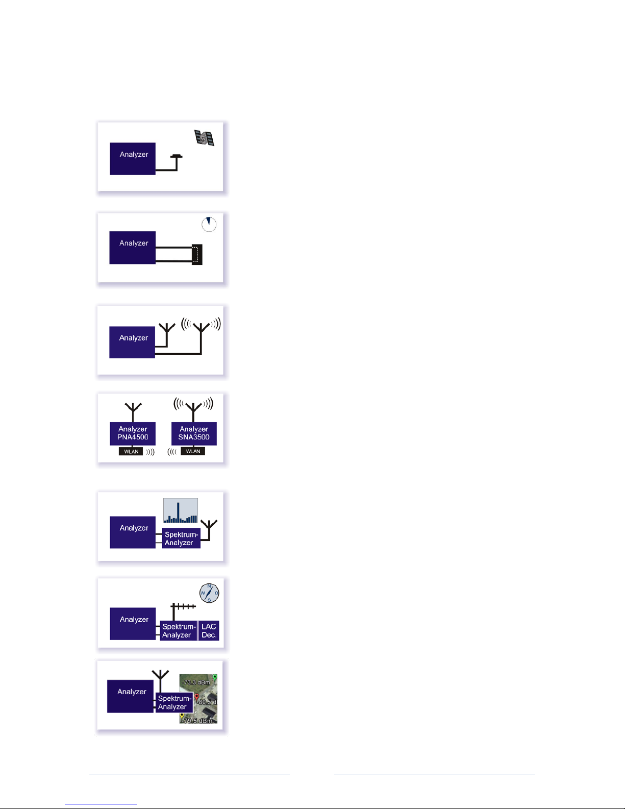
Review of the optional hard and software extensions (expected market launch in the course of 2017):
Software option: GPS antenna measurement
- Antenna testing
- GPS monitoring
- GPS accuracy display
Software option: Runtime measurement
Measure the signal runtime in an HF component (Group Delay)
Software option: Antenna radiation measurement
Measure the radiation and generate radiation diagrams
Software option: WLAN connection
From SNA 3500 and PNA 4500 until antenna radiation
measurement on several CW frequencies simultaneously
Hardware option: Measuring head for spectrum analysis
Measure the power of useful and interference signals within a
defined frequency range
Option: Panorama measurement with LAC decoding
Measure the alignment of a repeater attachment antenna for the
TETRA BOS object radio, including logfile for table generation
Software option: Field strength logging
Measure the signal strength of a frequency in time intervals with
position determination and log file creation. Display in Google Maps
Page 24
page
24
Setup of keyboard language
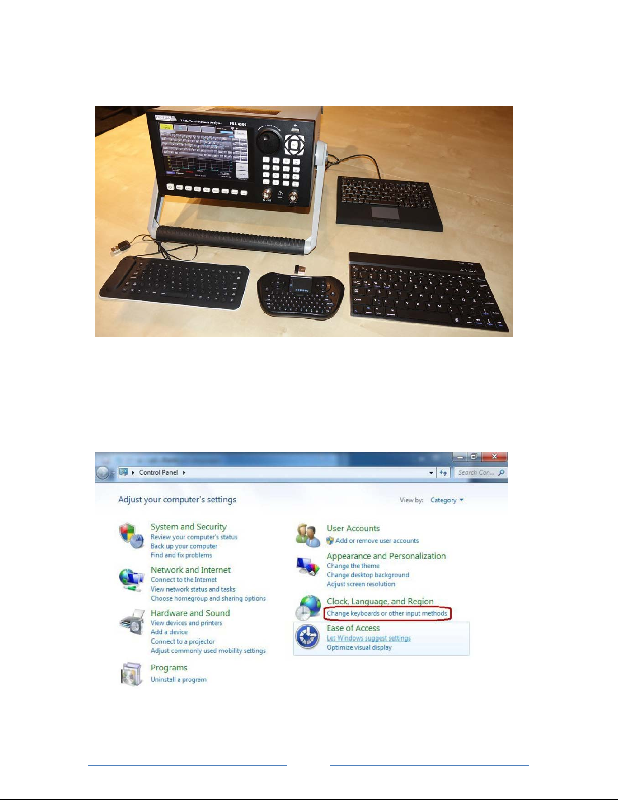
The PNA 4500 can be operated with different input devices, which are connected via the USB ports,
depending on the input possibilities the user prefers. The Windows functionality supports different
keyboard languages, so that you can use QWERTY or QWERTY keyboards. The on-screen keyboard
can also be changed accordingly. The keyboard language is set as follows:
1. Open the control panel and click on "CHANGE KEYBOARDS OR OTHER INPUT METHODS".
Page 25
page
25
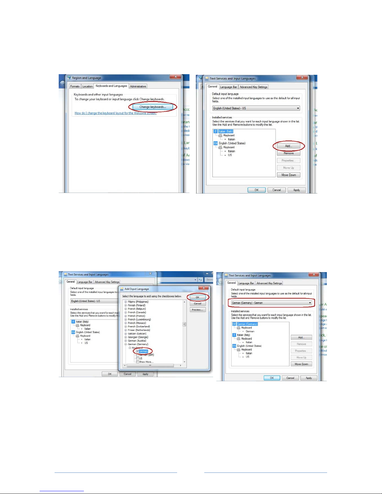
2. In the upper line, select the tab "KEYBOARD
AND LANGUAGES" and click the
"CHANGE KEYBOARDS" button.
3. Select “ADD“.
4. Use the "Arrow down" key to scroll down until
the desired language is reached. Then open the
entry and place the check mark accordingly. Then
confirm with "ok".
5. Now the desired language can be
selected instead of the default
language.
Page 26

page
26
Software update for the PNA 4500
If an update of the PNA 4500 software is necessary, the procedure is as follows:
1. Switch on the PNA 4500
2. Exit the PNA software (turn "SETUP" hardkey, "Setup 1/3" softkey to setup 3/3, press the
"Exit" softkey
3. Uninstall software:
- Press Windows "Start" or alternatively the arrow key "diagonally upper left"
- Select "default programs"
- Select "Program features"
- Select the software "PROTECS PNA4500" with the arrow keys "up" or "down"
- Uninstall software with "uninstall" as well as confirm the security query
4. Install new software:
- Save latest software version on a USB stick
- Connect the USB stick to the PNA 4500 and install the software.
Restart the PNA 4500 (press on/off button).
Note:
The saved pre-sets (pre-sets) and stored measurements will be retained.
Page 27

page
27
Specifications:
Description
Value
Model / device type
PNA 4500 Vector Network Analyser
Impedance
50 ohm
Possible measurements
S11, S21, amplification, impedance matching, DTF, spectrum
analysis and power measurement with external measuring
heads
Frequency range
100 kHz - 3 GHz
Source frequency accuracy
Less than 1 Hz
Frequency accuracy
± 5 ppm (+/- 0.0005%) @ 25 ° C
± 10 ppm (+/- 0.001%) over the entire operating temperature
range
Frequency stability
± 10 ppm (+/- 0.001%) over the entire operating temperature
range
Power output
-5 ÷ -30 dBm
Resolution of generator output level
1 dB
Accuracy of generator output level
± 1.5 dB
Bandwidth of the measurement
100 Hz - 150 kHz
Maximum power input @ 0 dB attenuation
Maximum
power input @ 7 dB attenuation
Maximum power
input with ext. power
measuring head
+20 dBm
+27 dBm
+40 dBm
Maximum input signal strength
+5 dBm @ 0 dB attenuation
+27 dBm @ ≥ 22 dB attenuation
Number of measuring points
Adjustable (depending on measuring method) 201, 401, 601,
801, 1.001 equidistant measuring points
Measuring speed
0.5 ms per measuring point
Dynamic range
Max. -100 dB
Operating system
Windows 7 built-in OS, 60GB SSD, 4GB RAM
Software for remote operation
Integrated HTTP server for remote control (PC, Tablet)
Storage capacity
Thousands of measurements and pre-sets
Weight
6.4kg (without battery)
Dimensions (L x W x H)
28 x 26 x 15 (cm)
Screen
7 "color monitor, touchscreen, 640 x 480 resolution
Connections of the measurement detectors
N connectors, 50 Ohm
Connections PNA 4500
3 x USB 2.0, 2 x USB 3.0, VGA, Ethernet RJ45
Battery long life (battery pack 400 mA/h)
Ca. 1 ½ h
Battery charging time (battery pack 400 mA/h)
Ca. 3 h via supplied 230 V AC charger
Temperature range
Operating temperature range: +5 ÷ 35 ° C
Storage temperature range: -10 ÷ 45 ° C
Changes and errors excepted. Version 8/2016.
 Loading...