

Page 1

Bus Manager
Installation Instructions
Introduction
The Bus Manager was designed to provide a protected “essential power bus” for
vehicles that rely upon critical electronic equipment for safe operation. This would
include aircraft with electronic ignition or electronic fuel injection systems. The Bus
Manager creates a protected 12 volt power source to ensure that these critical
systems keep working during vehicle operation. The Bus Manager also includes a
number of related functions to serve as a complete electrical distribution system.
Product Description
The Bus Manager system, when fully implemented manages a two battery vehicle
power system plus additional emergency power circuit paths to provide triple
redundant protection of essential bus powered systems. The basic functions of the
Bus Manager are:
1. Provides triple redundant Essential Bus protection.
2. Built-in Essential Bus and Main Bus relays.
3. Simple key switch input to activate Busses.
4. Alternator charge isolation for two battery system.
5. Automatic fuel pump monitoring and backup fuel pump switching without
using failure prone pressure switches.
6. Selection of engine start battery: select battery 1, battery 2 or both.
7. Emergency Power Switch function provides third level of Essential Bus
protection.
8. Easy to mount 6” x 4” x 2.5” fan cooled enclosure.
The Bus Manager has been designed for durability. The circuits and internal heat
sink have been thoroughly over designed to provide faithful service for many years.
The Bus Manager has been designed to be thermally stable without the use of the
included internal fan. The fan merely adds additional durability to an already rugged
system.
Past system architectures have used a pressure switch or manual switch to turn on a
back-up fuel pump in the case of primary pump failure. The Bus Manager monitors
the signal that is available from the fuel pressure sender typically found in an engine
monitor system. This is typically a VDO type pressure sender which have proven to
be very reliable. The Bus Manager monitors the signal from this sender to
determine if the primary fuel pump has degraded, and will automatically engage the
backup fuel pump when necessary. This valuable function can be utilized to engage
an electric backup pump when the primary pump is either mechanical or electric.
1
Page 2

The Bus Manager contains all the necessary logic circuitry and relay connections
internally. This makes for a very simple installation and hook up of the Bus Manager
system in the vehicle.
Parts included in this kit
Qty description
1 BMAN-1 Bus Manager control box
1 Bus Manager control harness
8 #10 x 10GA ring terminals
1 These instructions
Installation
Vehicle ground wiring
Grounding the vehicle systems
Proper operational of modern vehicle systems demands a good electrical grounding
system on the vehicle.
The vehicle chassis or frame should never be considered to be an electrical path.
The frame should be grounded at one point to the vehicle ground system. But other
vehicle systems should not rely on a connection to the frame as a method of
completing a circuit. All vehicle systems should have ground returns to a ground bus
which is in turn connected to the battery ground with an appropriate gauge return
wire.
The engine needs to have a large gauge ground wire connected to a secure bolt on
the engine case or block. Never use a motor mount bolt as a ground cable
connection point. Motor mount bolts experience a great deal of stress and
movement and can be the source of a grounding problem if the engine ground is
connected to them. The engine ground cable should be the same gauge wire that
connects the main +12V power feed to the starter motor.
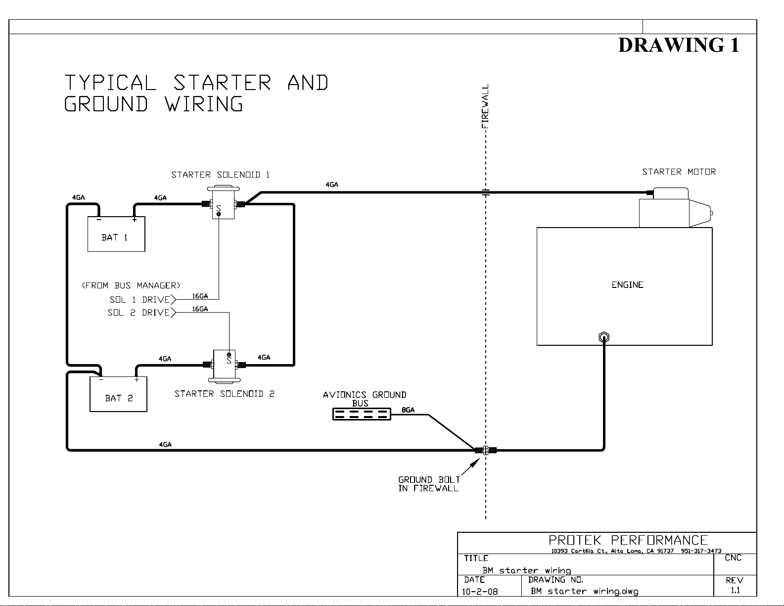
(refer to DRAWING 1)
If a ground bolt is used as a main ground pass through on the firewall, this is also a
convenient place to tie in the ground bus which all vehicle systems will be grounded
to.
The ground bus can be attached to the firewall ground bolt with a number 8GA
wire.
Starter motor wiring
(refer to DRAWING 1) The starter motor can be powered by either or both
batteries when using the Bus Manager. To use this feature, two starter solenoids are
required.
2
Page 3
These must be automotive type starter solenoids. Aircraft type master relays are
wired differently internally and are not suitable for this purpose. The starter
solenoids require a ground wire be connected to their mounting bracket to complete
their internal circuit. Typically the starter solenoids would be mounted near the
batteries to minimize the length of the large gauge wires that connect the solenoids
to the batteries.
Complete the large gauge wiring for the engine grounding, starter power and
solenoids as depicted on DRAWING 1.
Bus Manager Mounting
Find a mounting place for the Bus Manager in a convenient spot where it can be
accessed later. Under the instrument panel where there is room available would be a
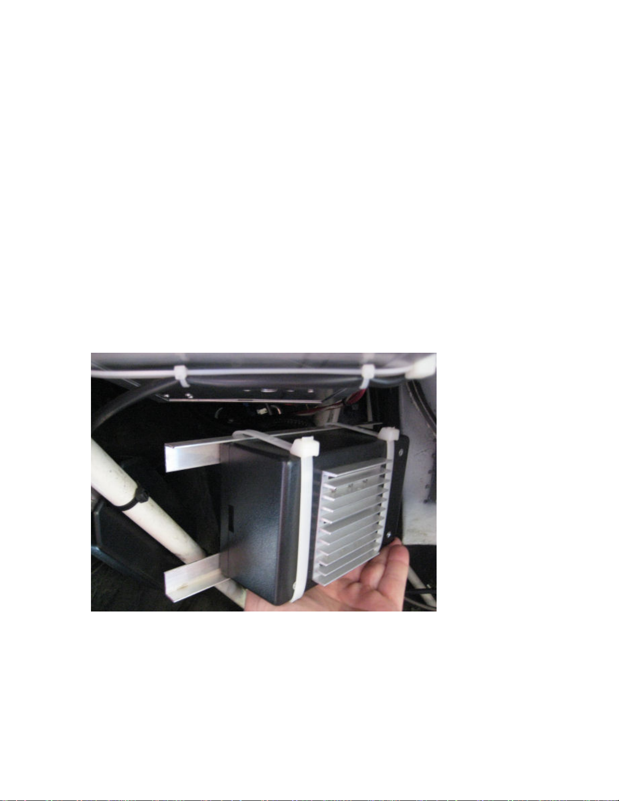
typical location for mounting. The easiest mounting method for the Bus Manager is
to use two 1/16” wall aluminum angles to cradle the bottom of the Bus Manager.
Two large tie wraps can then be used to secure the Bus Manager into the angles.
(see pics below).
Sample mounting using aluminum angle
3
Page 4
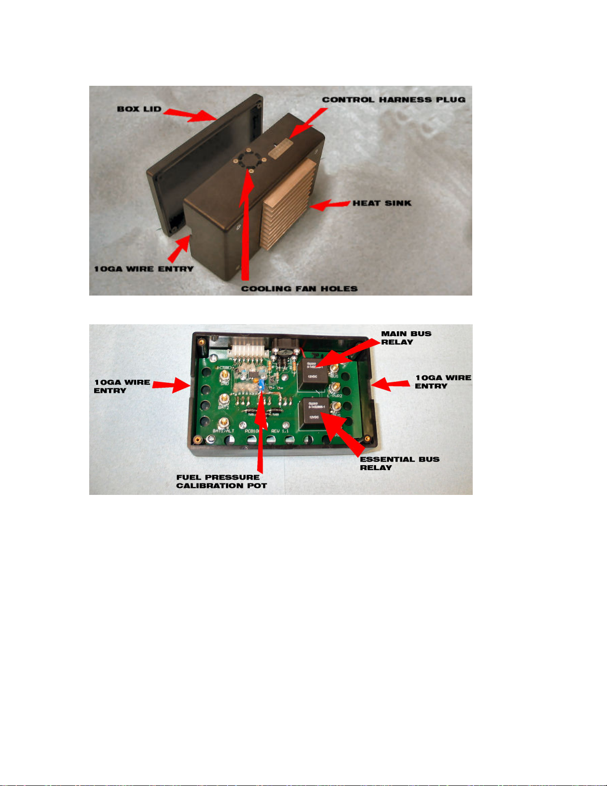
The Bus Manager from the outside
A look inside the Bus Manager
Note the cooling fan hole location on the side of the Bus Manager box as well as the
heat sink on the box. Air should be able to freely get to the heat sink and fan holes.
Do not mount either of these sides of the Bus Manager directly against other
equipment. Also note the location of the control harness plug on the Side of the Bus
Manager. This plug should be accessible at least during wiring.
After fabricating a mounting position, temporarily position the Bus Manager in
place with tape so that it can be easily removed for installation of the system wires.
4
Page 5

Bus Manager Bus Wiring
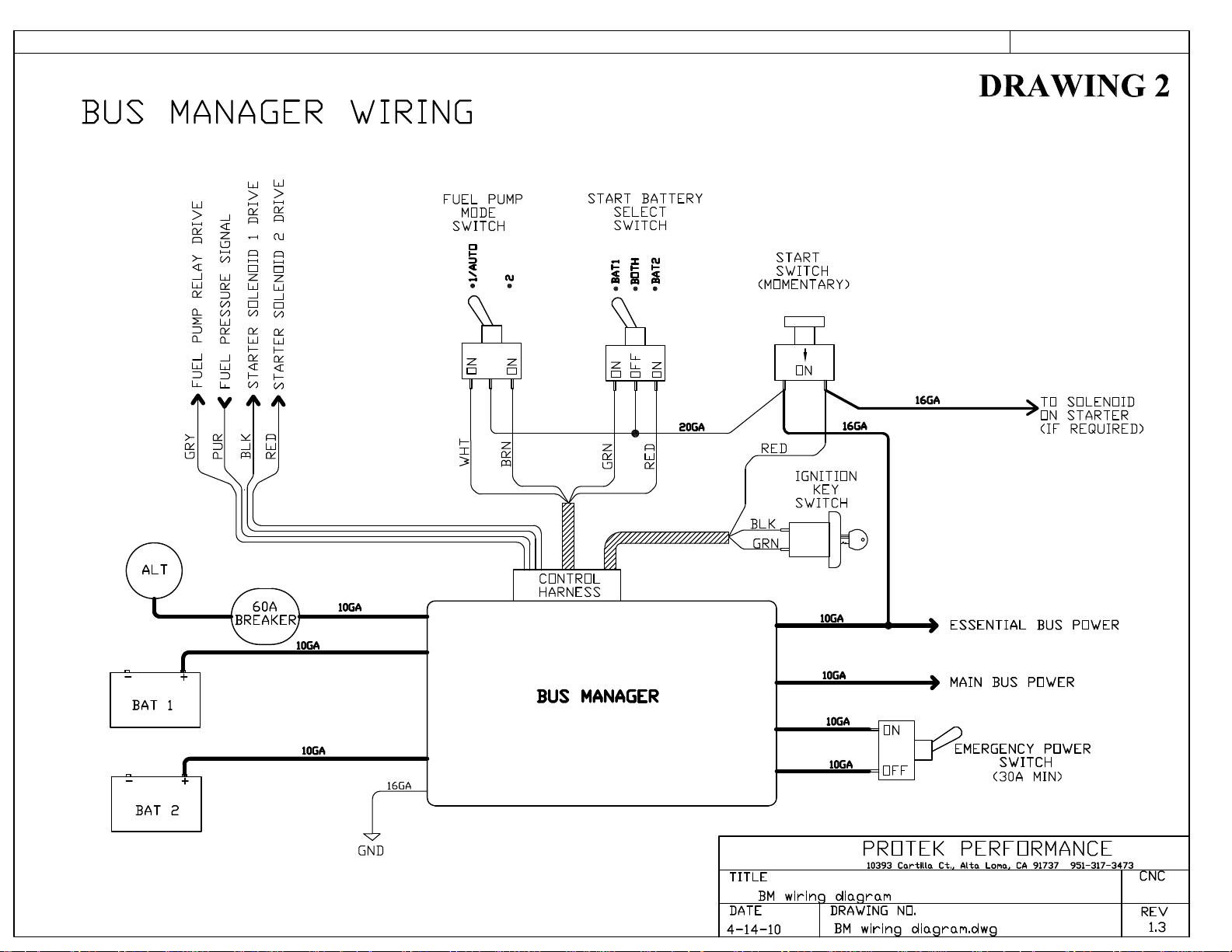
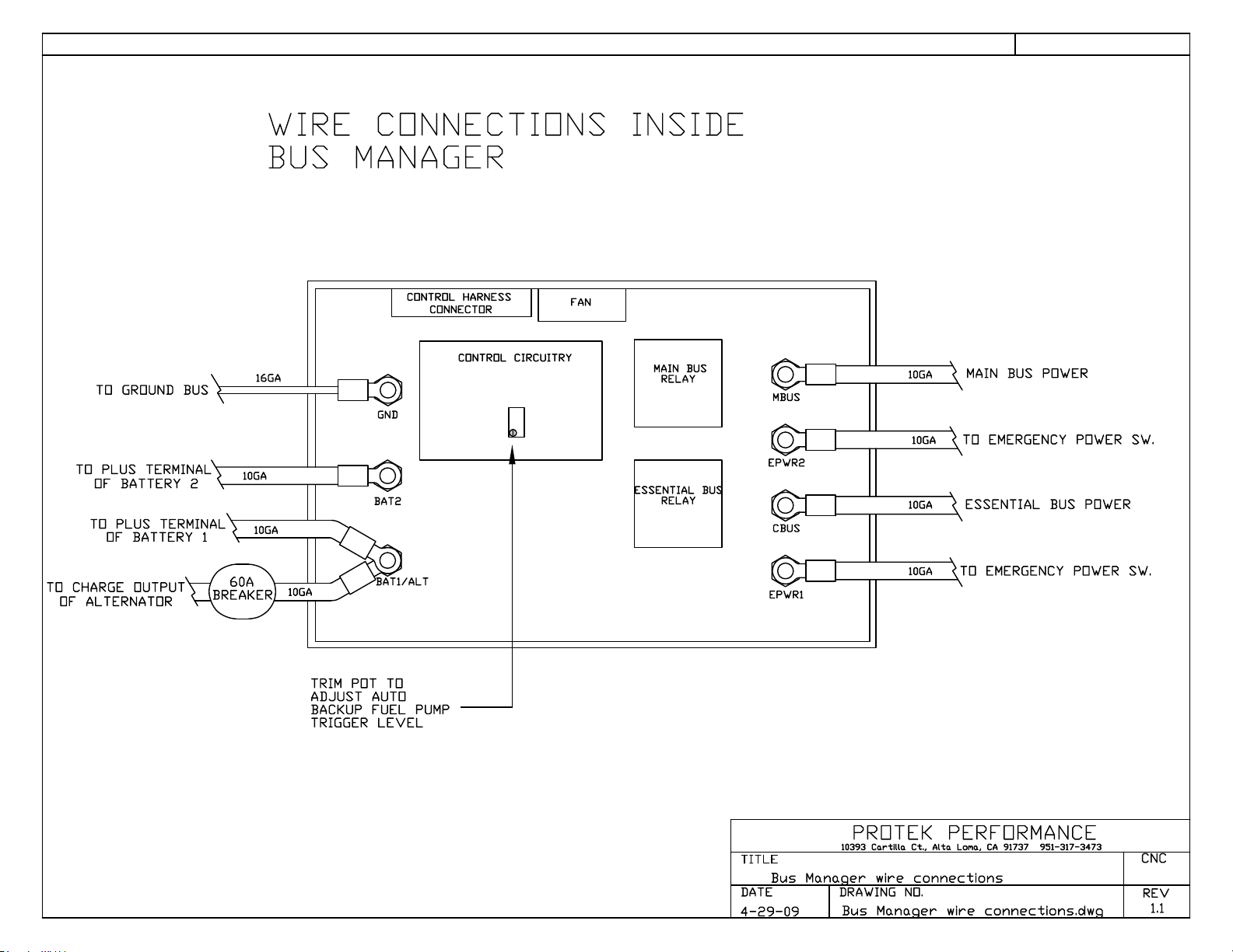
Wiring your Bus Manager system is very straight forward. Refer to DRAWING 2
and DRAWING 4.
Open the lid of the Bus Manager by removing the four small Phillips head screws
located on the face of the Bus Manager that is OPPOSITE the heat sink. Inside you
will see seven #10 screw terminals. These terminals will accept the 10GA wires
required for the system as well as the 16GA Bus Manager ground wire. Use the
included #10 crimp ring terminals to make your connections.
REFER to DRAWING 2
1. Connect a 10GA wire from the positive terminal of your primary battery
(battery 1) to the Bus Manager terminal labeled BAT1/ALT.
2. As shown on DRAWING 2, run a 10GA wire from your alternator charging
output post (usually a ¼” screw post on the alternator) to a 60A alternator circuit
breaker in your panel. Then run a 10GA wire from the 60A alternator breaker to
the Bus Manager terminal labeled BAT1/ALT. (The same terminal that you
connected to in the previous step).
3. Connect a 10GA wire from the positive terminal of your secondary battery
(battery 2) to the Bus Manager terminal labeled BAT2.
4. The Bus Manager requires a 16GA ground wire as shown on DRAWING 2. This
wire provides a ground connection for the control circuitry inside the Bus Manager.
Connect the Bus Manager ground to the vehicle ground bus.
5. Locate the terminal in the Bus Manager labeled EBUS (may be labeled CBUS).
This is the Essential Bus power output. This terminal will power all items critical to
the running of the engine. This includes alternator field power, fuel pump power,
ECU power, ignition power, and engine monitor power. The Essential Bus output is
rated for a 30A max continuous load. These items should have breakers or switches
where appropriate, grouped together in your panel layout. These “essential” items
should be wired such that they receive their power from the EBUS (or CBUS)
output of the Bus Manager. A convenient method of connecting items which are all
powered from the same source is to arrange them in a linear fashion on your panel
and screw a copper bar (or flattened piece of ¼” diameter copper tubing across the
devices. This would be referred to as “bussing” the items together. Using a 10GA
wire, the Essential Bus power output of the Bus Manager can then be connected to
this “Bus Bar”. Make sure all bus screw connections use lock washers and are
properly tightened.
5
Page 6

6. Locate the terminal in the Bus Manager labeled MBUS. This is the Main Bus
power output of the Bus Manager. This terminal will provide power for your other
aircraft accessories, such as lights, radios, autopilot, trim, etc. The Main Bus power
output is rated for 40A max continuous load. Items in your panel that will be
powered by the Main Bus should be grouped in a linear fashion and tied together
for power distribution with a bus bar as described in the previous section. Use a
10GA wire to connect the Main Bus output of the Bus Manager to the main bus bar.
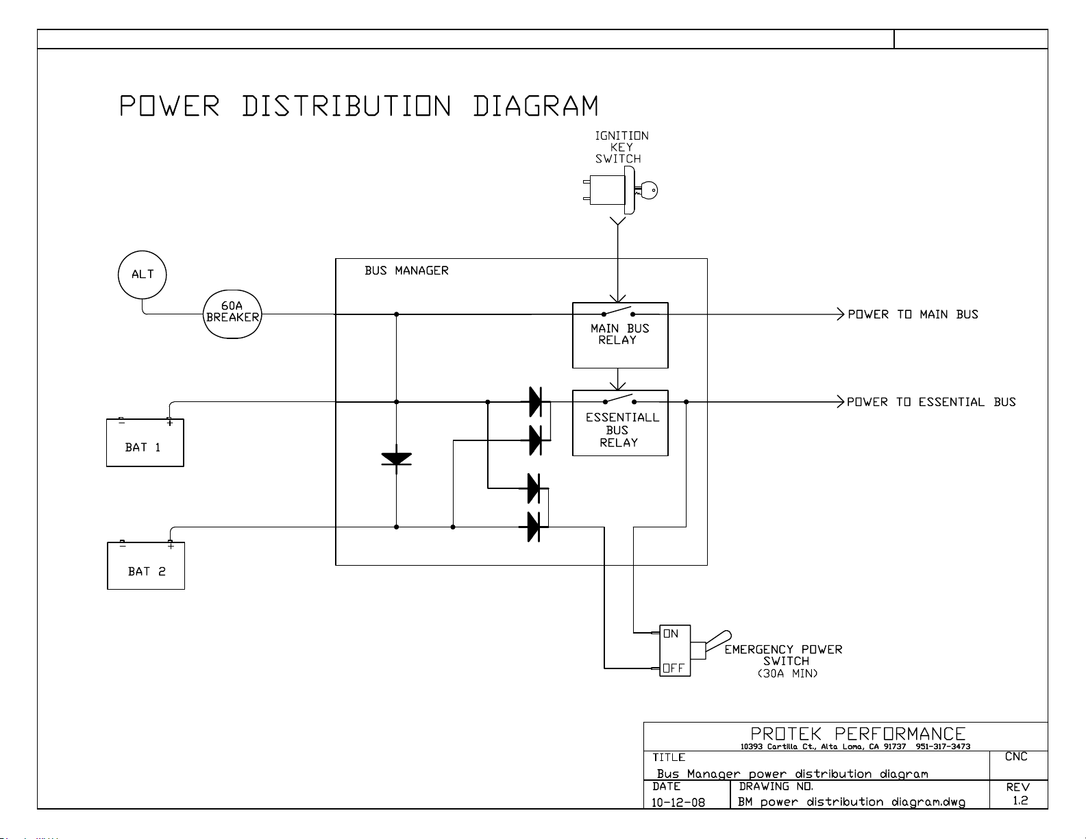
7. The Bus Manager is equipped with an Emergency Power circuit which when used
provides a third (triple redundant) electrical path to the Essential Bus. When
activated, the Emergency Power switch bypasses the normal circuit path through the
Bus Manager and directly connects the Essential Bus through a separate power
circuit to the batteries. See DRAWING 5. The Emergency Power Switch should be
connected as shown in DRAWING 4 to the E-PWR1 and E-PWR2 terminal within
the Bus Manager. An ON/OFF switch of at least 30A max rating must be used for
this purpose. Use 10GA wires to connect the Emergency Power Switch to the Bus
Manager. Some people prefer to locate the Emergency Power Switch in a semihidden location, while others prefer it to be readily accessible on the panel. In either
case, make sure it can easily be accessed while fully strapped into the vehicle.
Bus Manager Control Harness wiring
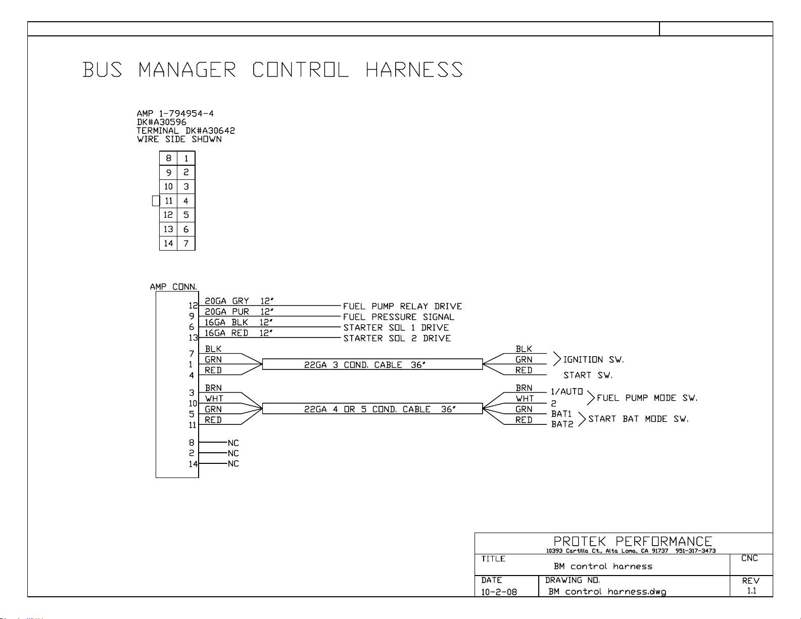
The Bus Manager control harness is a short harness in your kit with a 14 pin white
connector. This harness provides signals to the Bus Manager for operation of the
various control circuits. See DRAWING 2
A typical installation would include two mode switches, a start switch, and a key
switch. The Start Battery Select Switch determines which battery (or batteries) start
the vehicle engine. The Fuel Pump Mode Switch determines which fuel pump is
running if a backup fuel pump is used. The Start Switch initiates engine cranking
and the Key Switch turns on the system busses.
Start Battery Select Switch
This switch has three positions and is used to select whether the engine will be
started using battery 1, battery 2, or both batteries when using two starter solenoids
as shown on DRAWING 1. If the Start Battery Select Switch is not installed, and
the start solenoids are installed as shown, the Bus Manager solenoid drive wires will
always activate both solenoids during cranking and start the engine using both
batteries. If using the Start Battery Select Switch, wire it to the control harness as
shown on DRAWING 2.
Fuel Pump Mode Switch
This switch has two positions and determines the fuel pump drive operation of the
Bus Manager. When in position “1/Auto” (the normal operating position), fuel
pump 1 will be running and operating the engine. The Bus Manager will
6
Page 7

continuously monitor the fuel rail pressure by tapping into the signal wire from the
fuel pressure sender that is connected to your engine monitor. If the fuel rail
pressure drops below a precalibrated limit, the bus Manager will automatically turn
on fuel pump 2. When in position “2”, fuel pump 2 is forced on and fuel pump 1 will
be turned off. Wire the Fuel Pump Mode Switch to the control harness as shown on
DRAWING 2.
Start Switch
The Start Switch is a momentary switch (normally open or OFF), which when
activated, will engage the starter motor and crank the engine. Wire the Start Switch
to the control harness as shown in DRAWING 2.
Key Switch
The Key Switch is a key lock ON/OFF switch. When this switch is activated, the Bus
Manager internal bus relays will be activated and the Essential Bus and Main Bus
outputs of the Buss Manager will become hot. Wire the Key Switch to the control
harness as shown in DRAWING 2.
Additional control harness wires
Starter Solenoid 1 drive (black wire)
This wire is used to activate Starter Solenoid 1 as shown on DRAWING 1.
Connect as required using 16GA wire. NOTE – starter solenoid mounting bases
must be grounded to complete their internal circuit.
Starter Solenoid 2 drive (red wire)
This wire is used to activate Starter Solenoid 2 as shown on DRAWING 1.
Connect as required using 16GA wire. NOTE – starter solenoid mounting bases
must be grounded to complete their internal circuit.
Fuel Pump Relay drive (grey wire)
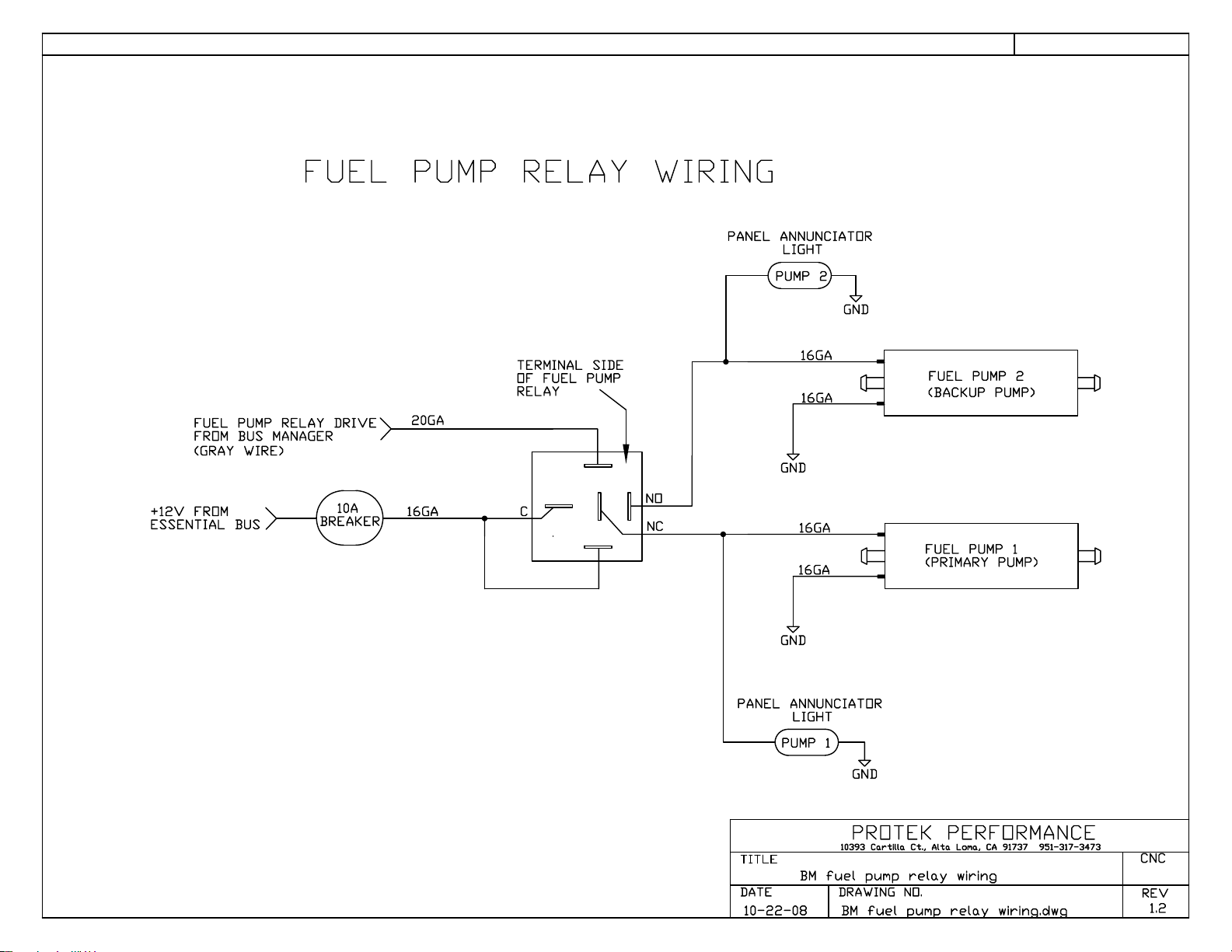
This wire is used to activate the fuel pump relay as shown on DRAWING 3.
If using the Bus Manager to manage a backup electric fuel pump, wire the pumps
according to DRAWING 3, using a 10A circuit breaker to supply power to the fuel
pump system.
Fuel Pressure Signal (purple wire)
This wire normally taps into the output wire of the fuel pressure sender that is part
of your engine monitor system. The Bus Manager monitors the voltage on this wire
to determine if you have normal fuel pressure. If the fuel pressure drops below a
precalibrated limit, the Bus Manager will automatically activate the backup fuel
pump (assuming you have configured you pumps according to DRAWING 3).
Connect this wire to the signal output wire coming from your fuel pressure sender.
7
Page 8

Using the Bus Manager
The Bus Manager is very simple to use. Once hooked up, it becomes a transparent
part of the vehicle electrical system that requires little pilot input or monitoring.
The Start Battery Select Switch is generally left in one position – most people will
leave it in the BOTH position and start the engine using both batteries. The
exception to this might be if one battery is dead. Then the engine could be started
off only the good battery so that the dead battery doesn’t draw power from the
system during cranking.
The Bus Manager will test all portions of the auto fuel pump backup circuit during
start-up. Typically the Fuel Pump Mode Switch begins in the 1/AUTO position. As
the key switch is turned on, the fuel pump backup circuit will instantly detect low
fuel pressure since no pump had been running. This will cause the Bus Manager to
automatically engage the backup fuel pump and it’s associated annunciator lamp
will come on. The pilot then resets the backup system by moving the Fuel Pump
Mode Switch to PUMP 2 and then back to PUMP1/AUTO. This will reset the
monitoring circuit and engage pump 1. This process tests all circuits and both pumps
giving the pilot comfort in knowing that all aspects of the fuel system are operative.
The Start Switch is then used to start the engine normally.
The Main Bus and Essential Bus will become hot as soon as the Key Switch is
turned on. Systems powered by the Main bus can be turned on at any time
considered appropriate.
Calibrating the Auto Backup Fuel Pump Circuit
The Bus Manager can be calibrated to trigger the backup fuel pump at any desired
fuel pressure. EFI systems typically have a fuel pressure regulator system that is
compensated by manifold pressure. In other words, the fuel pressure will go up and
down as manifold pressure goes up and down with application of throttle. It is
desired to select a fuel pressure trip point for the Bus Manager that is below the
normal operating range of fuel pressure. This will prevent the backup fuel pump
from coming on when conditions are normal. It is common for the fuel pressure to
vary by as much as 7 or 8 PSI during normal engine operation. If you activate one of
the fuel pumps with the engine NOT running, this is your static fuel pressure.
Subtract 10PSI from this pressure to determine a reasonable trip point for the
backup fuel pump system. In other words, if your static fuel pressure (one pump ON
and engine OFF) is 35PSI. Then a trip point of 25PSI would be reasonable to decide
that there is a fuel pressure problem and that the secondary fuel pump should be
engaged.
8
Page 9

In order to set the fuel pressure at which the Bus Manager will engage the backup
fuel pump, remove the Bus Manager cover (opposite the heat sink side of the box).
You will see a rectangular trim pot in the middle of the circuit board as shown in
DRAWING 4. There is a small screw on the top of the trim pot that is used to adjust
the trip point of the backup fuel pressure system. If you turn the trim pot screw
clockwise, the trip point pressure will go up. If you turn the trim pot screw
counterclockwise, the trip point pressure will go down.
You will need to have your fuel system fully operative to test the trip point. If you
find that the Bus Manager always activates pump 2 and will not reset to activate
pump 1, then the trip point is too high and must be lowered. Once you have the trip
point set so that pump 1 will remain on after a reset of the Fuel Pump Mode Switch
(switch to PUMP 2 then back to PUMP 1/AUTO), you can then determine what
pressure the backup system trips at by pinching off the fuel coming to your fuel
pumps. This can usually be done with flat jaw vise grips or seaming pliers used to
pinch down the fuel line feeding the pumps. Watch the fuel pressure as shown on
your engine monitor. As you pinch the line, the fuel pressure will begin to drop and
you can witness at what pressure the backup system engages pump 2. With a couple
of adjustments, you should be able to calibrate the Bus Manager to activate pump 2
at the desired trip point pressure.
9
Page 10
Page 11
Page 12
FUEL PUMP RELAY WIRING
DRAWING 3
FUEL PUMP RELAY DRIVE
FROM BUS MANAGER
(GRAY WIRE)
+12V FROM
ESSENTIAL BUS
10A
BREAKER
20GA
16GA
TERMINAL SIDE
OF FUEL PUMP
RELAY
C
NO
NC
PANEL ANNUNCIATOR
LIGHT
PUMP 2
16GA
16GA
GND
16GA
16GA
GND
GND
FUEL PUMP 2
(BACKUP PUMP)
FUEL PUMP 1
(PRIMARY PUMP)
PANEL ANNUNCIATOR
TITLE
DATE
10-22-08
LIGHT
PUMP 1
10393 Cartilla Ct., Alta Loma, CA 91737 951-317-3473
BM fuel pump relay wiring
DRAWING NO.
BM fuel pump relay wiring.dwg
GND
PROTEK PERFORMANCE
CNC
REV
1.2
Page 13
WIRE CONNECTIONS INSIDE
BUS MANAGER
DRAWING 4
TO GROUND BUS
TO PLUS TERMINAL
OF BATTERY 2
TO PLUS TERMINAL
OF BATTERY 1
TO CHARGE OUTPUT
OF ALTERNATOR
10GA
60A
BREAKER
16GA
10GA
10GA
TRIM POT TO
ADJUST AUTO
BACKUP FUEL PUMP
TRIGGER LEVEL
CONTROL HARNESS
GND
BAT2
BAT1/ALT
CONNECTOR
CONTROL CIRCUITRY
FAN
MAIN BUS
RELAY
ESSENTIAL BUS
RELAY
MBUS
EPWR2
CBUS
EPWR1
10GA
10GA
10GA
10GA
MAIN BUS POWER
TO EMERGENCY POWER SW.
ESSENTIAL BUS POWER
TO EMERGENCY POWER SW.
PROTEK PERFORMANCE
TITLE
Bus Manager wire connections
DATE
4-29-09
10393 Cartilla Ct., Alta Loma, CA 91737 951-317-3473
DRAWING NO.
Bus Manager wire connections.dwg
CNC
REV
1.1
Page 14
POWER DISTRIBUTION DIAGRAM
DRAWING 5
IGNITION
KEY
SWITCH
ALT
BAT 1
BAT 2
BUS MANAGER
60A
BREAKER
+-
+-
MAIN BUS
RELAY
ESSENTIALL
BUS
RELAY
ON
OFF
EMERGENCY POWER
SWITCH
(30A MIN)
POWER TO MAIN BUS
POWER TO ESSENTIAL BUS
PROTEK PERFORMANCE
TITLE
Bus Manager power distribution diagram
DATE
10-12-08
10393 Cartilla Ct., Alta Loma, CA 91737 951-317-3473
DRAWING NO.
BM power distribution diagram.dwg
CNC
REV
1.2
Page 15
BUS MANAGER CONTROL HARNESS
AMP 1-794954-4
DK#A30596
TERMINAL DK#A30642
WIRE SIDE SHOWN
8
1
2
9
10
3
11
4
12
5
13
6
14
7
AMP CONN.
20GA GRY 12"
12
20GA PUR 12"
9
16GA BLK 12"
6
16GA RED 12"
13
BLK
7
GRN
1
RED
4
BRN
3
WHT
10
GRN
5
RED
11
22GA 3 COND. CABLE
22GA 4 OR 5 COND. CABLE
FUEL PUMP RELAY DRIVE
FUEL PRESSURE SIGNAL
STARTER SOL 1 DRIVE
STARTER SOL 2 DRIVE
36"
36"
BLK
GRN
RED
BRN
WHT
GRN
RED
IGNITION SW.
START SW.
1/AUTO
2
BAT1
BAT2
DRAWING 6
FUEL PUMP MODE SW.
START BAT MODE SW.
8
2
14
NC
NC
NC
TITLE
DATE
10-2-08
PROTEK PERFORMANCE
10393 Cartilla Ct., Alta Loma, CA 91737 951-317-3473
BM control harness
DRAWING NO.
BM control harness.dwg
CNC
REV
1.1
 Loading...