

Page 1
Proteco Electric Lock & Interface Card Installation for Q71A & B
Components Required:
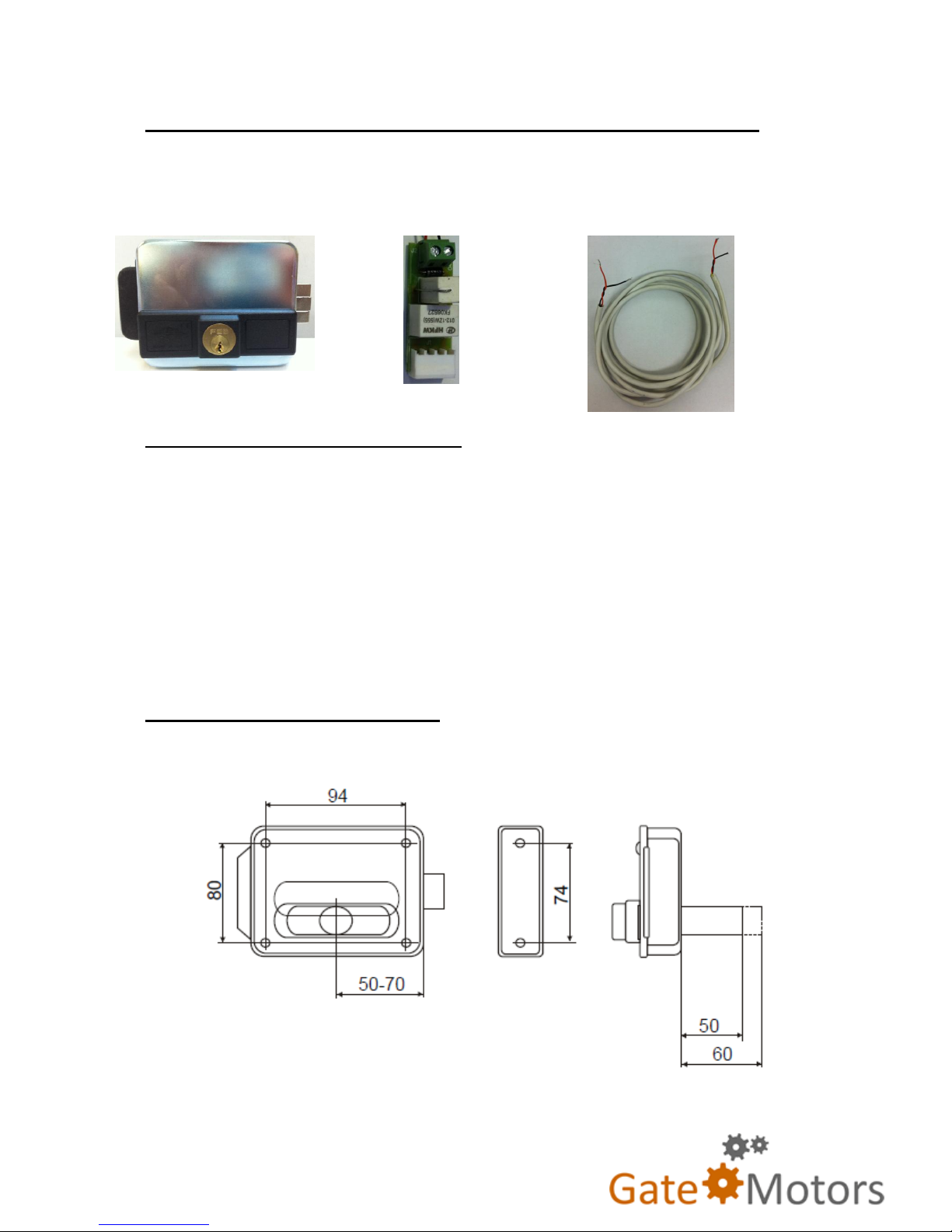
1 x Horizontal Lock 1 x MEL 56 Interface Card 1 x 2 core CAT5 / Alarm Cable
Installing the Lock onto the Gate
For Double Gates: Fit the horizontal lock on the leading edge of the
leaf that will be opening first and closing second. Fit the striker plate
onto the gate that opens second and closes first.
For Single Gates: Fit the horizontal lock on the leading edge of the
gate and fir the striker plate onto the post or pillar that the gate is
closing up to.
Dimensions of Horizontal Lock
Measurements in millimetre (mm)
Barrel length is 50mm long with a 25mm diameter
Page 2
Installing the Lock onto the Gate
For Double Gates: Fit the horizontal lock on the leading edge of the
leaf that will be opening first and closing second. Fit the striker plate
onto the gate that opens second and closes first.
For Single Gates: Fit the horizontal lock on the leading edge of the
gate and fir the striker plate onto the post or pillar that the gate is
closing up to.
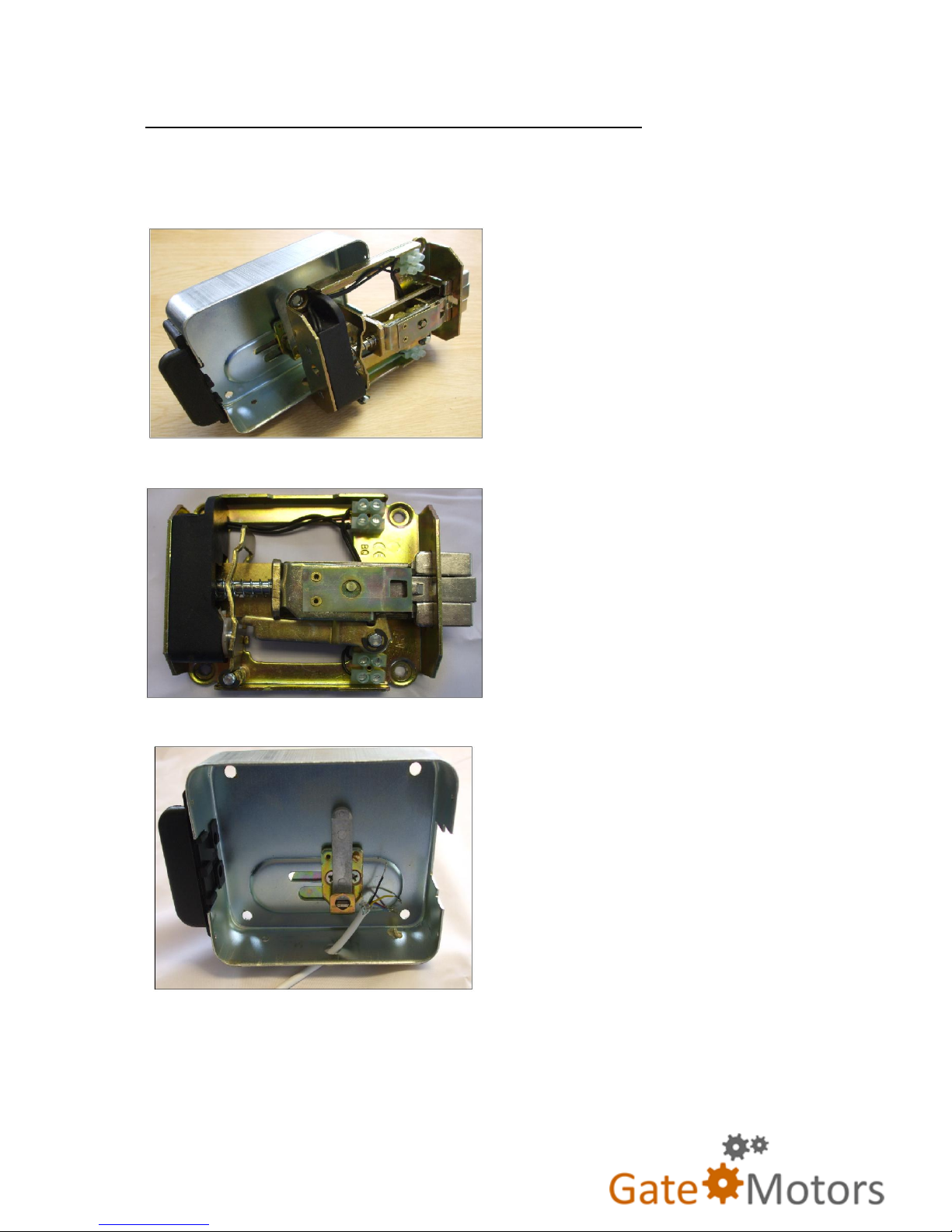
The lock arrangement is defaulted for left hand gates.
For right handed gates, the lock will need to be rotated inside its
cradle.
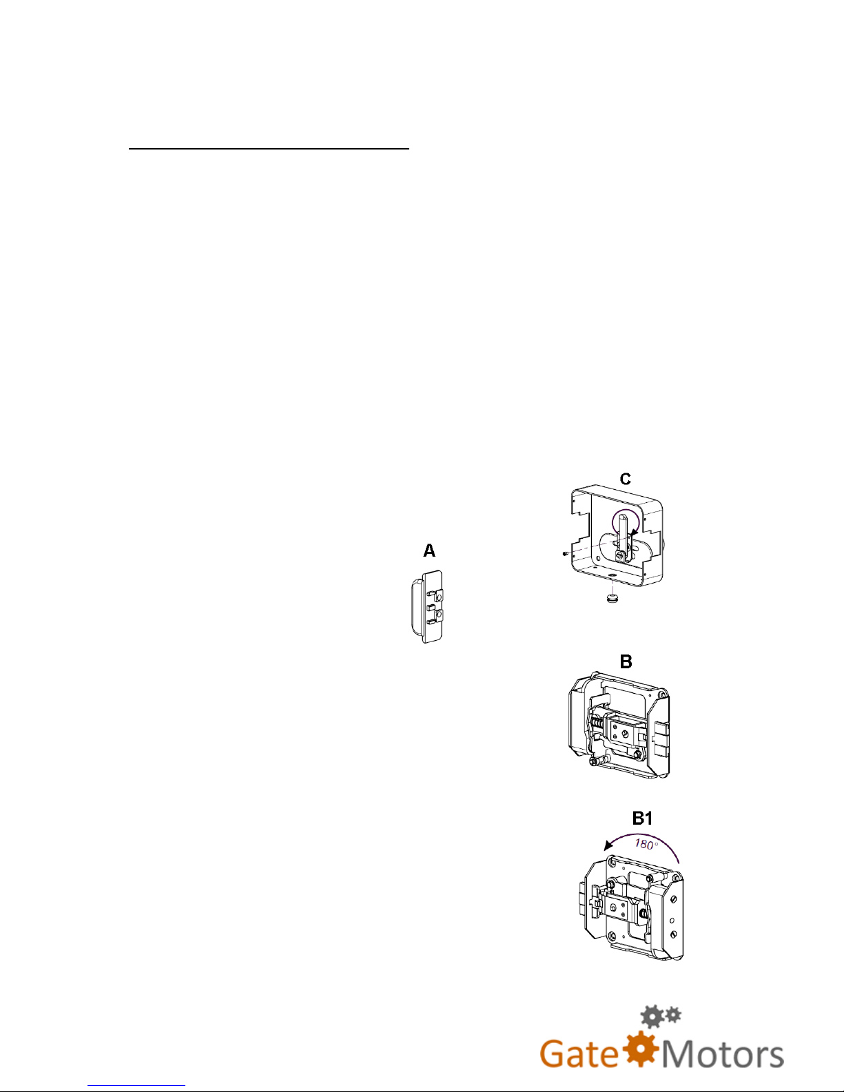
Step 1 – Remove rubber cable grommet from
bottom of cradle - C.
Step 2 – Remove end cap – A
Step 3 – slide lock mechanism out of cradle,
leaving it on its own – B
Step 4 – rotate Lock mechanism 180 degrees - B1
Page 3
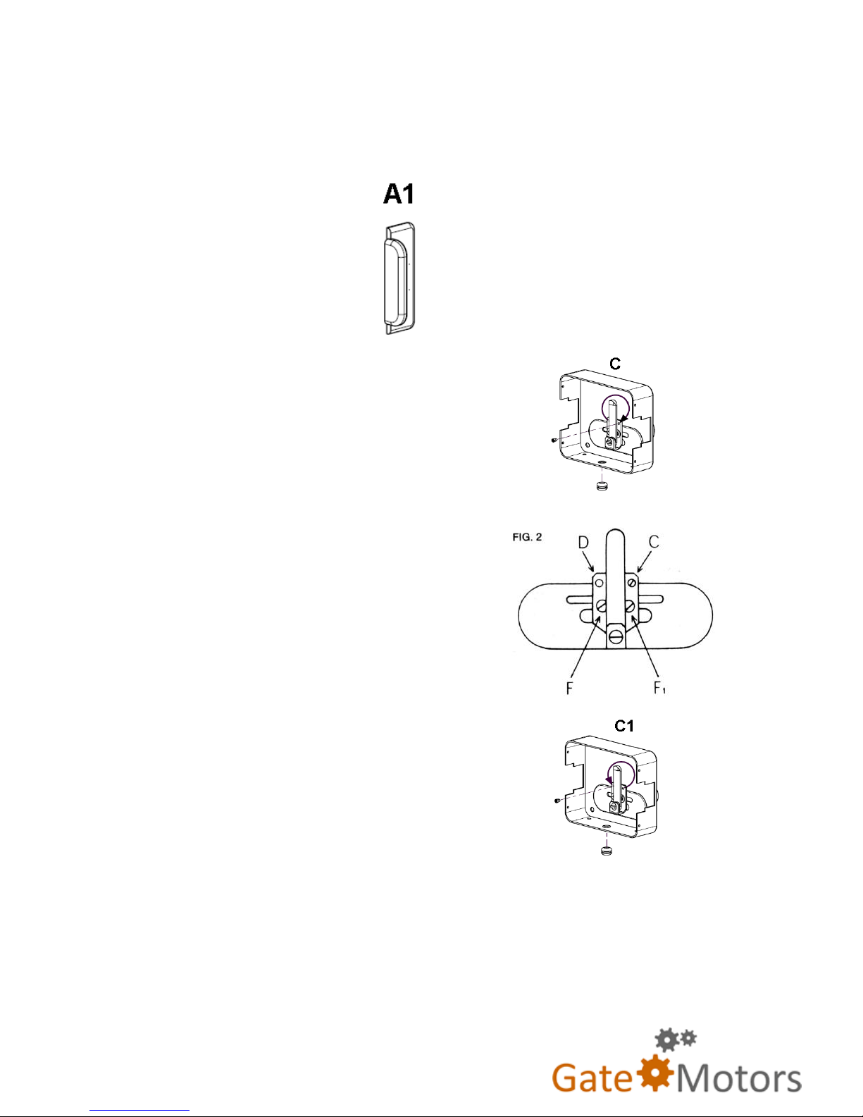
Step 5 – Slide lock mechanism into cradle and replace end cap on
other end of cradle – A1
Step 6 – Remove locking screw for the key
release – C.
(Fig.2 hole C illustrated right)
Move to the left and place into hole D.
The arrangement should look like C1
(Illustrated right)
Step 7 – Replace rubber grommet
Page 4
Fixing Lock onto the gate
Choose location for installing the lock
on the leading edge of the gate and cut
out hole for the barrel feed. The barrel
diameter is 25mm.
Length of Barrel is 50mm
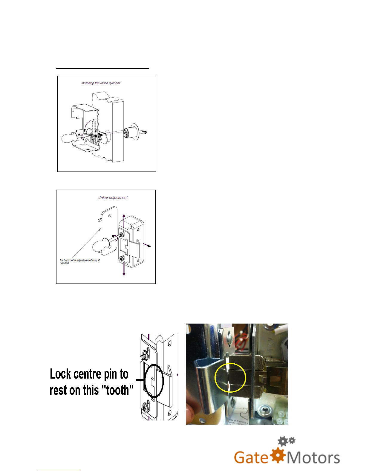
Line striker with the lock and fix
securely to pillar. For minor adjustment
of the striker plate, unscrew two screws
on the plate and move up, down for to
the right.
It is important to ensure the lock centre pin is resting on the striker
plate “tooth” – Illustrated below
Page 5
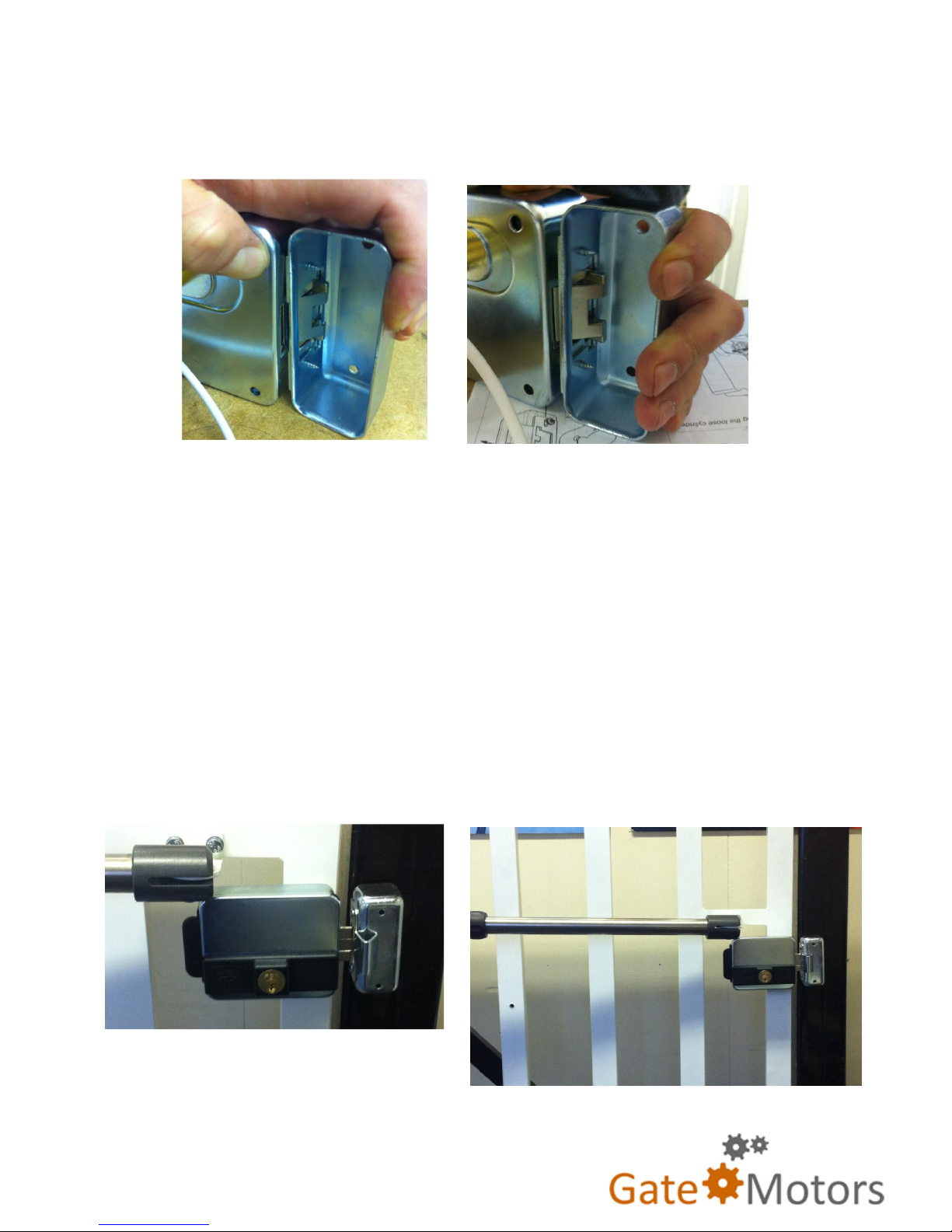
Only the centre pin of the lock sits outside the striker plate unit – the
rest of the lock pin mechanism sits inside – Illustrated below:
The above is critical to the locks operation. When the lock receives a
12v charge from the MEL 56, the tension in the spring mechanism
releases and a loud “snap” sound is heard. This releases the centre
pin which mechanically stops the rest of the lock pin mechanism
from moving.
When finalising the fixing of the lock to the gate, ensure the lock is in
a stationary stable solid state - The lock should be either welded or
bolted to the gate appropriately.
Page 6
Wiring of the Electric Lock & MEL 56 Interface card
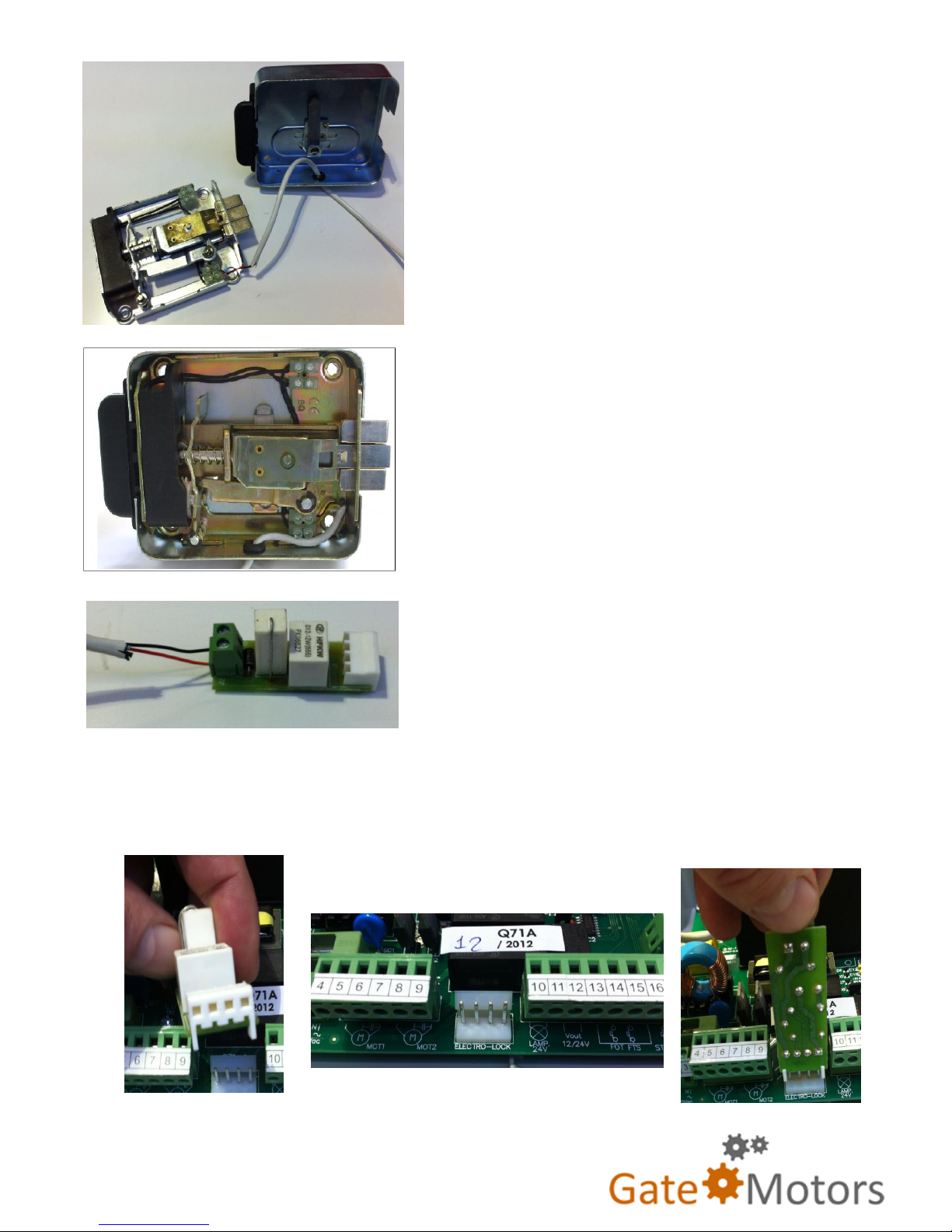
Before replacing the cover of the lock, connect the lock terminals to
the gate automation control board.
INSTALL TIP
It may be easier to access
the terminal block by
removing the locking
mechanism from its cradle.
Depending on which side the
lock is being fitted (left hand
leaf or right hand leaf), use
the according terminal block.
For example here: This lock
is being mounted on the left
hand leaf.
Feed 2 core cables through
the hole provided in the casing
before wiring to the terminal
block. The example here is
using a 4 core alarm cable,
but using two strands – Yellow
and Black.
Page 7
Place your two cables into the
terminal strip, and screw tightly.
Keep the cable clear of the sides
when placing back into the casing;
this will avoid pinching of the cable
and possible strand damage.
If you have removed the lock from its
cradle - Place the locking mechanism
back into place, being careful not to
pinch the cable. Once in place, feed
the black rubber cable grommet
along the cable and place in the hole.
Place two cables into the MEL 56
interface unit as shown and screw
tightly.
Between Terminals 9 and 10 (illustrated below) is the location
of the 4 pin Electric Lock input.
Page 8
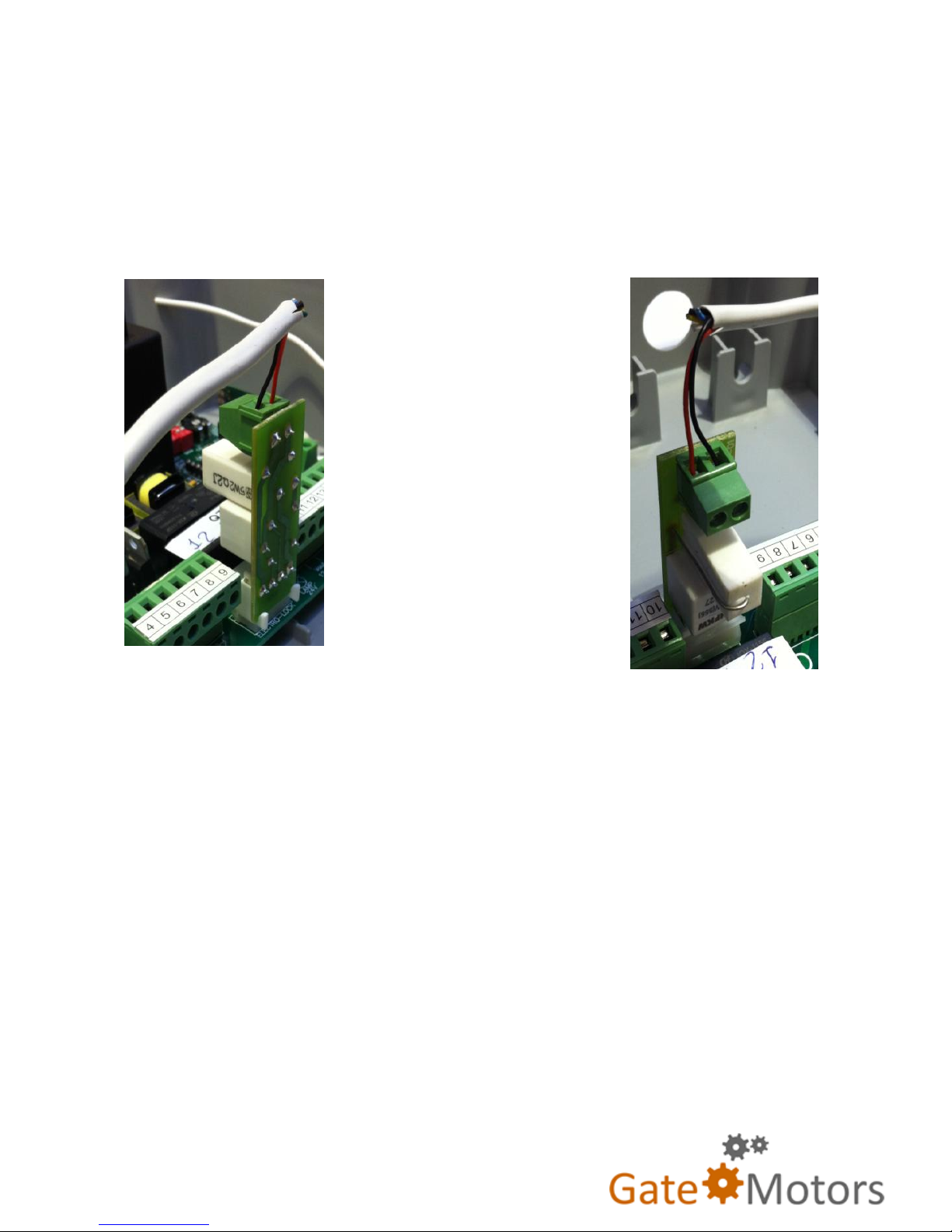
Place the MEL 56 unit onto the male pin socket on the Q71.
Ensure the pins slot into the MEL 56 female socket tightly.
Press gently with your
finger to ensure good
contact. The card should
look like pictures shown
(left).
There is a clear plastic clip
on the MEL socket which
keeps the card in place on
the board. The clip will
make a “snap” sound
when the MEL card is
fitted.
No Alterations to the control board / programming needed.
 Loading...