

Page 1
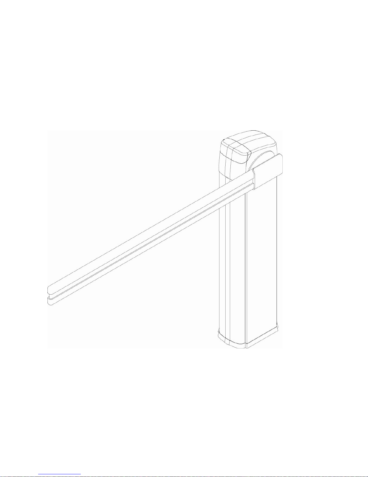
BARRY
BARRIER GATE AUTOMATION
Installation Manual
Page 2

1. WARNINGS AND GENERAL SAFETY INSTUCTIONS
This manual contains important safety information.
An incorrect installation or an improper use may cause serious damages to persons or objects.
Read this manual carefully and completely. and store it safely for future use
Pay particular attention to the sections marked by the symbol:
Always disconnect main power supply before starting installation or maintenance.
Make sure that the earth system is perfectly working and always connect the barrier to it.
An earth leakage breaker is needed on the main power supply.
Keep away from children radio transmitters and any other device which the automation
can unconsciously be activated by.
§ As for the electric cable type and section, we recommend you to use a <HAR> type cable with
minimum section of 2.0mm².
§ Do not change the original inside wiring.
§ In case of power failure, please switch off the mains first, then open the door and rotate the
handle on the motor manually to completely lift the boom.
§ Use radio transmitters or any other control only when the automation is clearly in sight.
§ Never open the door or lift the cover of the barrier when it is working
§ Do not allow children to play in the automation area.
§ Fixed control systems must be installed at a minimum height of 1.5m from the ground.
The installation of automatic gates and doors must fully comply with the requirements set forth
in 2006/42/EC Directive, with particular reference to EN 12445 and EN 12453 standards.
The final connection to the electrical mains, testing and start -up of the automation must be
performed by skilled and qualified personnel, who is responsible for carr ying out the risks
analysis and verifying the compliance of the system with the current safety standards.
This product is exclusively designed and manufactured for the intended use specified in this
manual. Any other use than stated could compromise the integrity and the safety of the product
and therefore is strictly prohibited
Use exclusively original parts for maintenance.
Do not carry out any alteration on the components of the automatic road barrier.
Proteco S.r.l. declines all liability in case not original components or additional devices are used.
Automatic road barriers are not for pedestrians! BARRY road barriers are designed for
vehicular traffic only. Direct all pedestrian traffic to a separate walk-through gate.
2. TECHNICAL SPECIFICATIONS
AC models DC models
Power supply: 220V 50Hz Power supply: 220V 50 Hz
Motor’s power: 90W/220Vac Motor’s power: 80W/24Vdc
Revolutions: 2800r/min Revolutions: 1400r/min
Opening time: 6” (boom 4 to 6 m) Opening time: 6” (boom 4 to 6m)
Max boom’s length: 6m Max boom’s length: 6m
Page 3
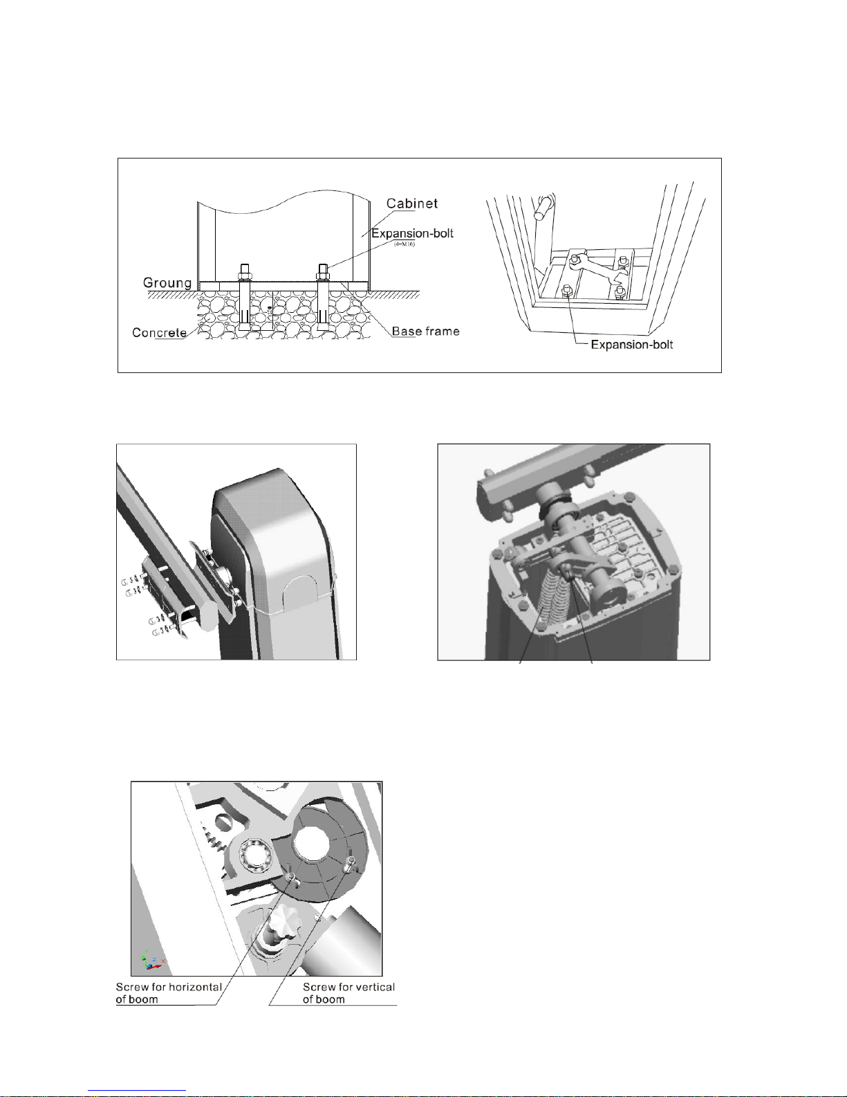
3. INSTALLATION
3.1 Fixing to the ground
Fig.1
3.2 Assembling the boom
Fig.2 Fig.3
3.2 Limit-switch adjusting
The magnetic limit-switch and the mechanical limit-switch of the barrier are already pre-set for an
optimal movement of the boom. Limit-switches position doesn’t need to be changed.
Fig.4
Spring
Adjusting nut
Page 4
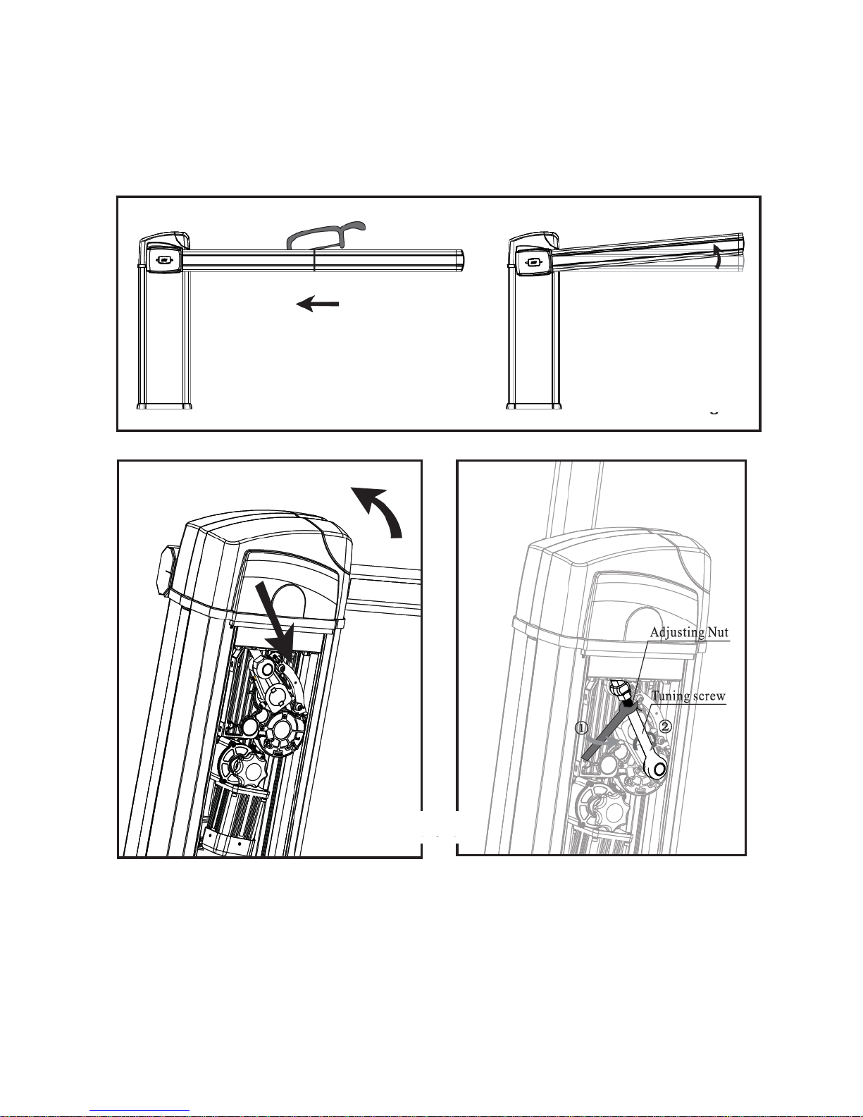
4. ADJUSTING THE BOOM
4.1 Short boom
In case you need to use a shorter size of the telescopic boom, please pay attention to the
following adjustments
1. Move the boom manually to the upright position
2. Unfasten the adjusting nut
3. Adjust the tuning screw till the boom is perfectly upright
4. Tighten the adjusting nut
The boom could slightly raise once
shorted. In this case, you might need to
reduce the springs quantity (please see
appendix).
Fig. 5
Fig.
6
Page 5
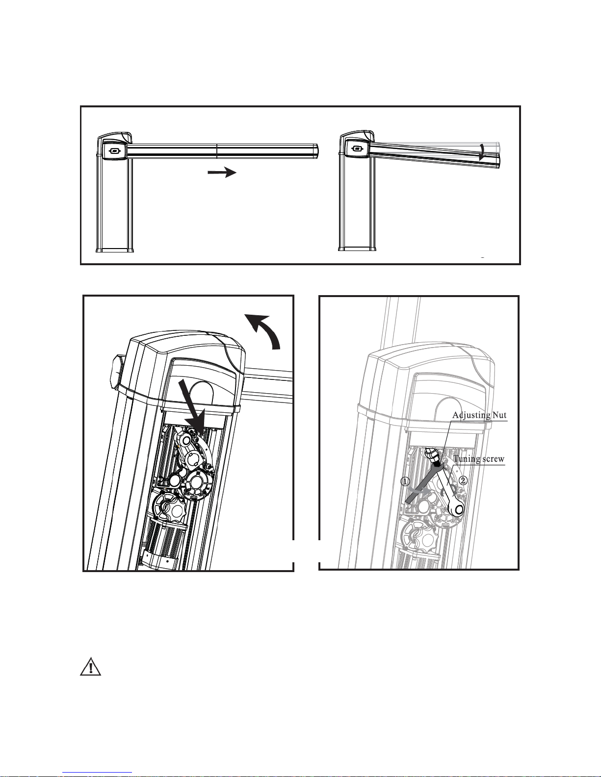
4.2 Long boom
In case you need to use the longest size of the telescopic boom, please pay attention to the
following adjustments
1. Move the boom manually to the upright position
2. Unfasten the adjusting nut
3. Adjust the tuning screw till the boom is perfectly upright
4. Tighten the adjusting nut
Balancing springs adjustment
The springs are already pre-set for a perfect balancing according to the boom’s length.
In some cases (very short or very long boom) you may need to re-adjust the balancing springs.
Please see the appendix and pictures 5,6,7,8.
The boom could slightly slope
downward once longer
. In this case, you
might need to increase the springs
quantity (please see appendix).
Fig. 7Fig.
8
Page 6
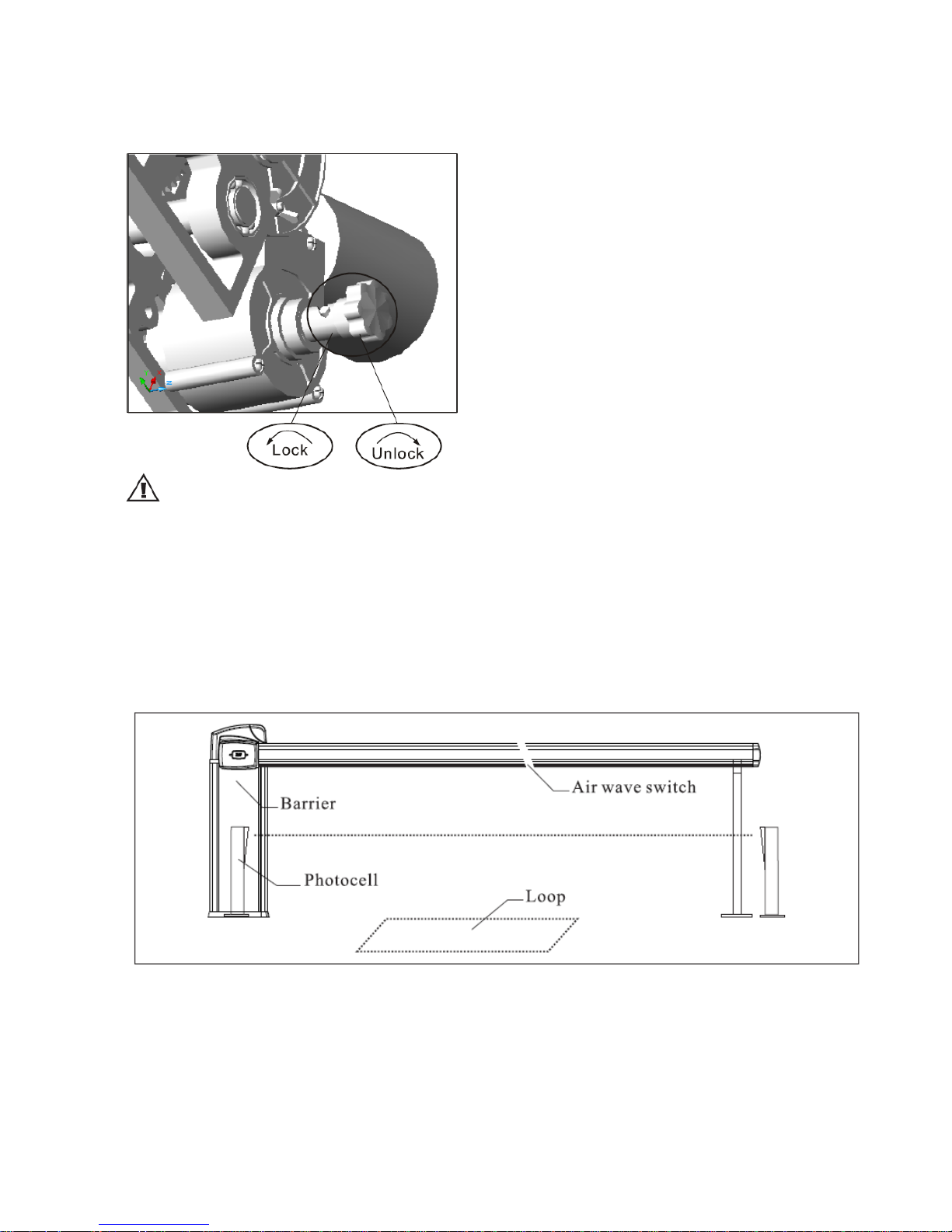
5. RELEASE FOR MANUAL OPERATION
Please see picture below
Fig.5
When unlocking the boom could suddenly move upwards. Always control the boom
movement with your hands.
6. ELECTRICAL SET-UP
Motor, control panel and limit-switches are already wired.
Optional controls or safety devices, such as photocells, loop detectors or air-wave switches can be
connected to the automatic road barrier.
Page 7
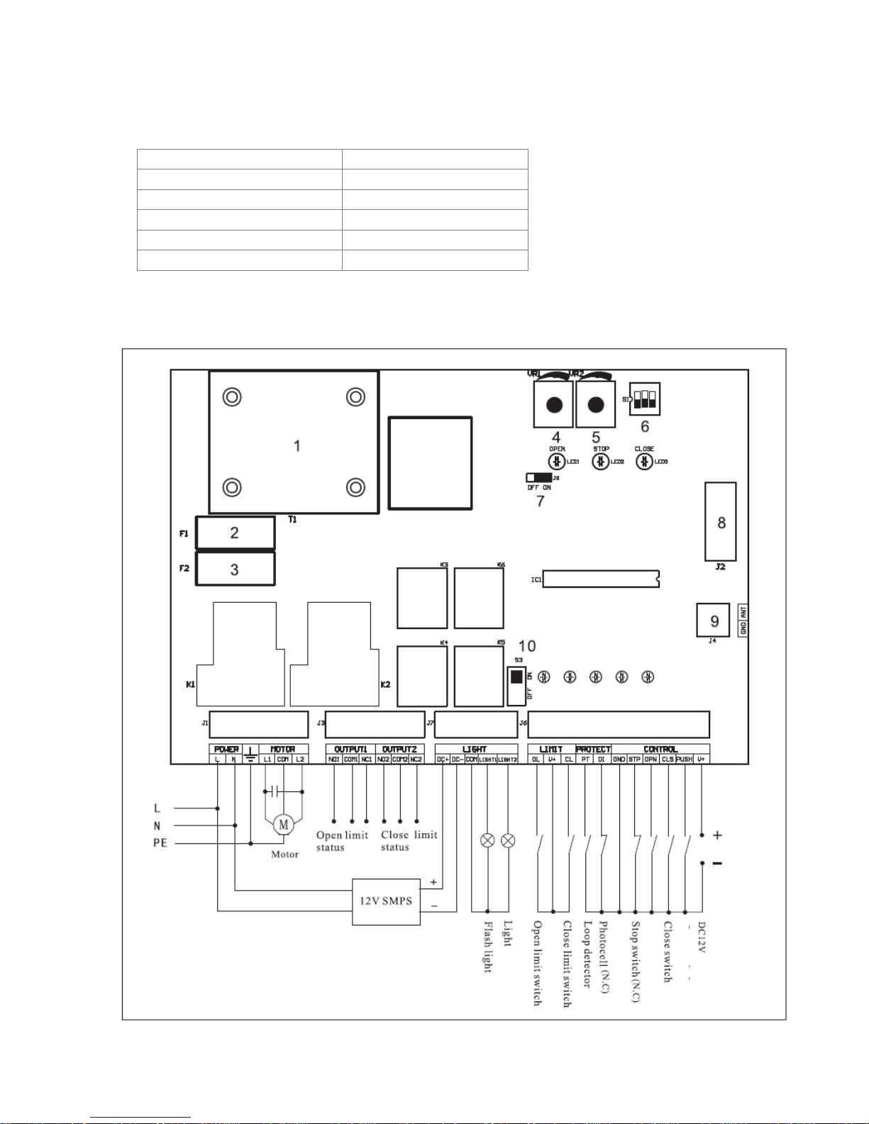
7A. WIRING AND PROGRAMMING SET-UP (AC version)
7A.1 Technical specifications
Power supply AC 230V 50Hz/ 110V 60HZ
Max. consumption 10W
Accessories power supply DC12V 8W MAX
Working temperature - 20°C ~ +50°C
Radio transmitters frequency 433,92 Mhz
Automatic closing pause 1 -120”
7A.2 Wiring Scheme (AC version)
Push button
Open switch
Page 8
1 – T1: Transformer
2 – F1: 0.2A fuse
3 – F2: 5A fuse
4 – VR1: Working force potentiometer
5 – VR2: Pause time for automatic closing
potentiometer
6 – S1: DIP switch block
7 – Reverse function jumper (ON= function
enabled)
8 – Plug for receiver module
9 – Terminal for aerial
10 – Power switch for lights
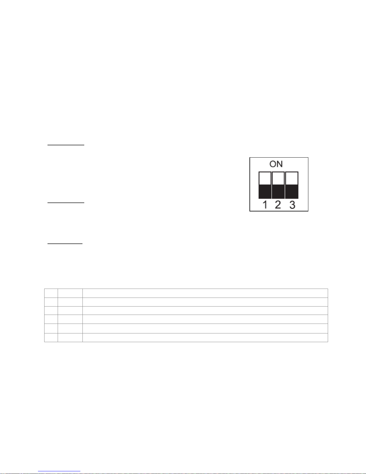
7A.3 Programming DIP-switches
DIP-switch 1:
ON – An air-wave switch is wired to the PT terminal on the control
panel, the boom reverses when the airwave beam is obstructed
OFF - A loop detector is wired to the PT terminal on the control
panel, if a car enters into the loop’s range the boom stays open.
When the car leaves the loop area the barrier closes.
DIP-switch 2:
ON – Automatic closing function is enabled, the pause time can be
adjusted by VR2 potentiometer.
OFF- Automatic closing function is off.
DIP-switch 3: Not used
7A.4 Signalling LEDS
Nr Name Meaning
1 OL Opening limit-switch LED: it lights on once the barrier has completed the opening
2 CL Closing limit-switch LED: it lights on once the barrier ha s completed the closing
3 PT Air-wave switch. It lights on when the air-wave beam is obstructed by an obstacle.
4 LP Photochells LED: it get off when the photo-cells beam is obstructed by an obstacle.
5 Power Power supply LED . It lights on when the automation is powered
Page 9
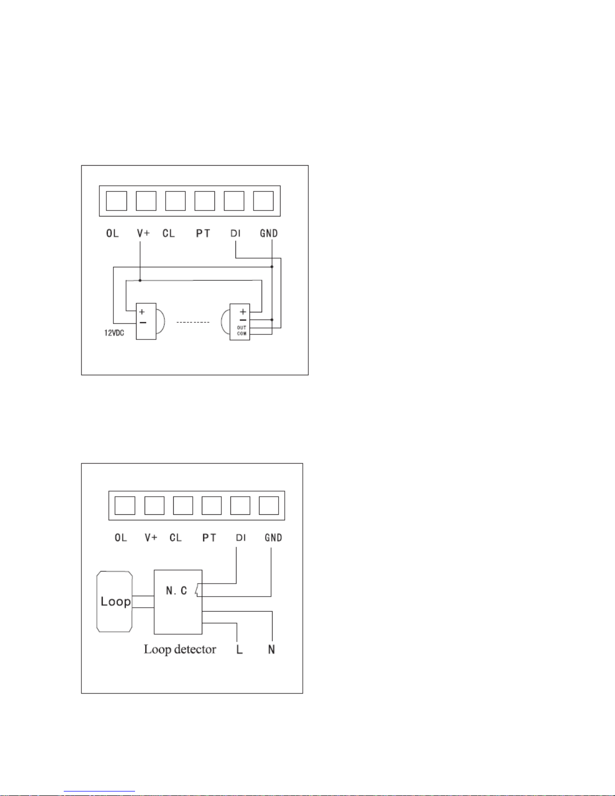
7A.5 Opening Safety Devices
7A.5.1 PHOTOCELLS (NC contact)
- If the infrared beam is obstructed when closing, the barrier immediately reverses
- If the infrared beam is obstructed when opening, the barrier keeps opening.
7A.5.2 LOOP DETECTOR (NC contact)
- If a car enters in the loop’s range when closing, the barrier immediately reverses
- If a car enters in the loop’s range when opening, the barrier keeps opening.
Note: If the automatic closing function is on, the barrier automatically closes after a pause time.
The pause time can be set from 1 to 120 seconds
Transmitter
Receiver (NC)
Page 10
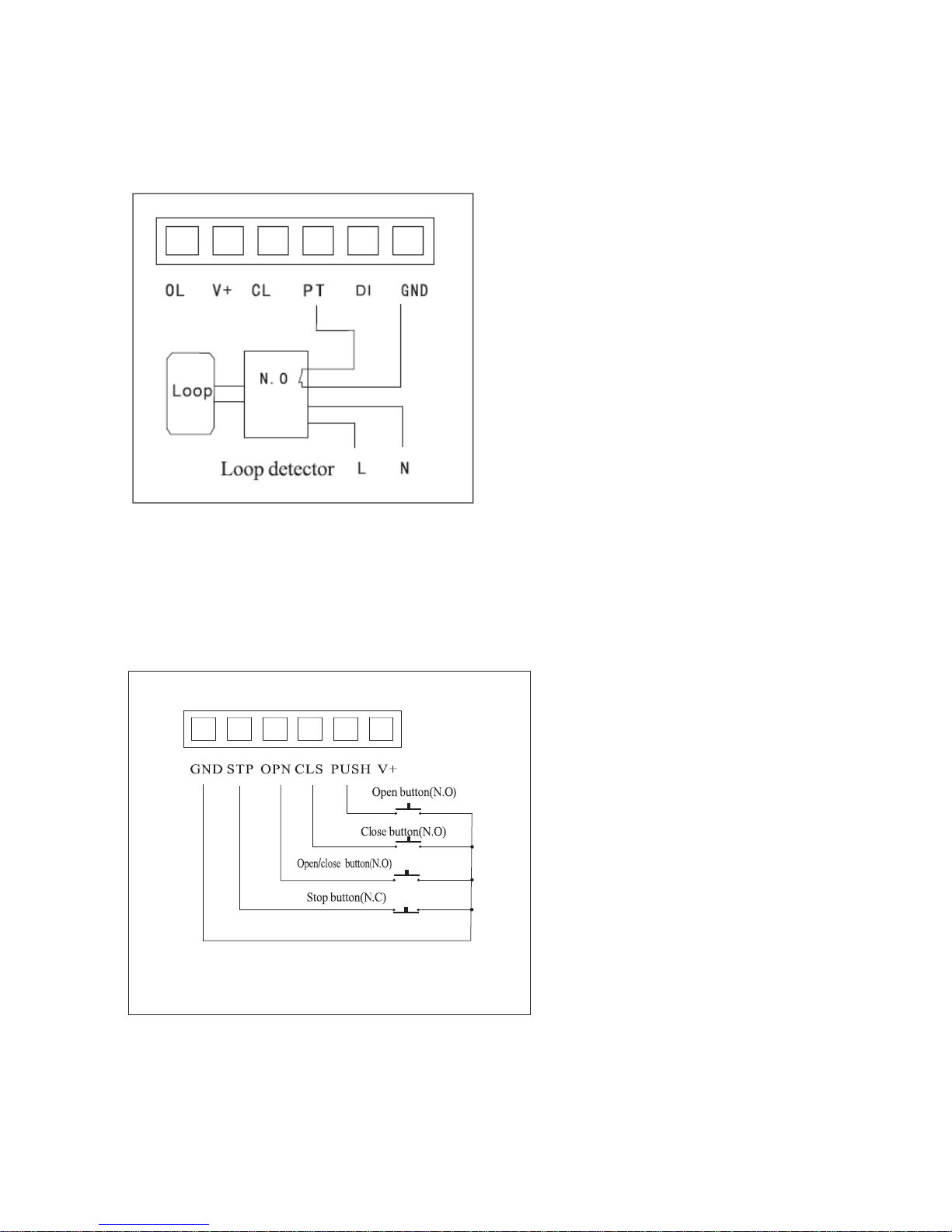
7A.5.3 LOOP DETECTOR (NO contact)
(DIP-switch 2 must be in OFF position)
- If a car stops in the loop’s range, the barrier stays open
- Once the car leaves the loop’s range when opening, the barrier closes.
7A.6 External Terminal
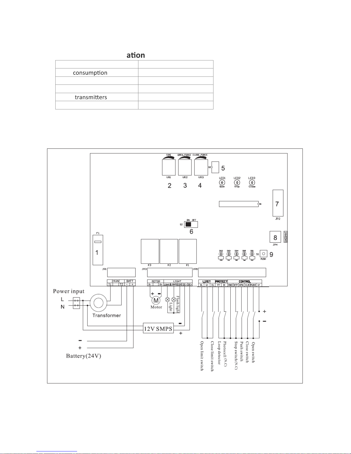
When an IC card reader is used, it has to be wired to OPN and GND terminals.
Page 11
7B. WIRING AND PROGRAMMING SET-UP (DC version)
7B.1 Technical specific s
Power supply AC 230V 50Hz/ 110V 60HZ
Max. 120W
Accessories power supply DC24V 10W MAX
Working temperature - 20°C ~ +50°C
Radio frequency 433,92 Mhz
Automac closing pause 1 -120”
7B.2 Wiring Scheme (DC version)
dc 24V
Page 12
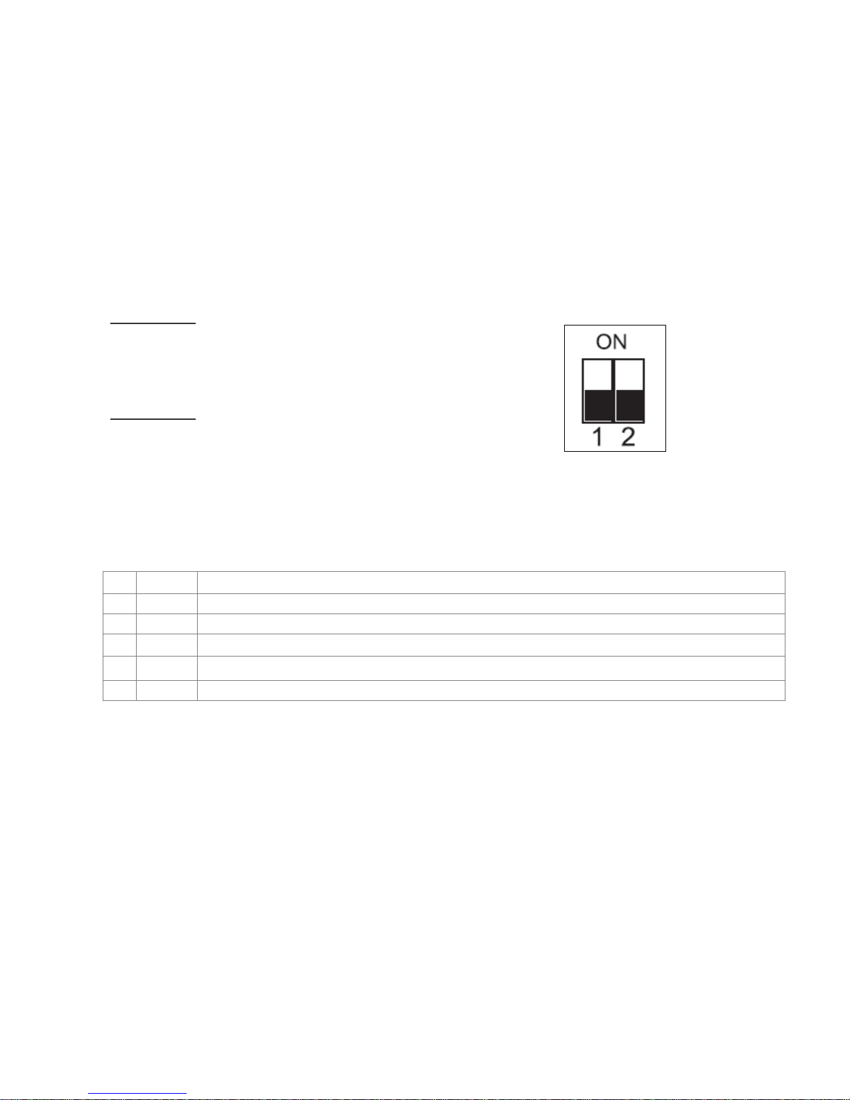
1 – F1: 8A fuse
2 – VR1: Pause time for automatic closing potentiometer
3 – VR2: Opening force potentiometer
4 – VR3: Closing force potentiometer
5 – DIP-switch block
6 – Power switch for lights
7 – Plug for receiver module
8 – Terminal for aerial
9 – Button
7B.3 Programming
DIP-switch 1:
ON – Automatic closing function is enabled, the pause time can be
adjusted by VR1 potentiometer.
OFF- Automatic closing function is off.
DIP-switch 2:
ON – The flashing light is off when the barrier is in stop status.
OFF - The flashing light is on when the barrier is in stop status.
7B.4 Signalling LEDs
Nr Name Meaning
1 DS2 Opening limit-switch LED: it lights on once the barrier ha completed the opening
2 DS3 Closing limit-switch LED: it lights on once the barrier ha completed the closing
3 DS4 Air-wave switch. It lights on when the air-wave detects an obstacle
4 DS5 Loop detector LED: it lights on when a car enters in the loop’s range
5 Power Power supply LED . It lights on when the automation is powered
Page 13
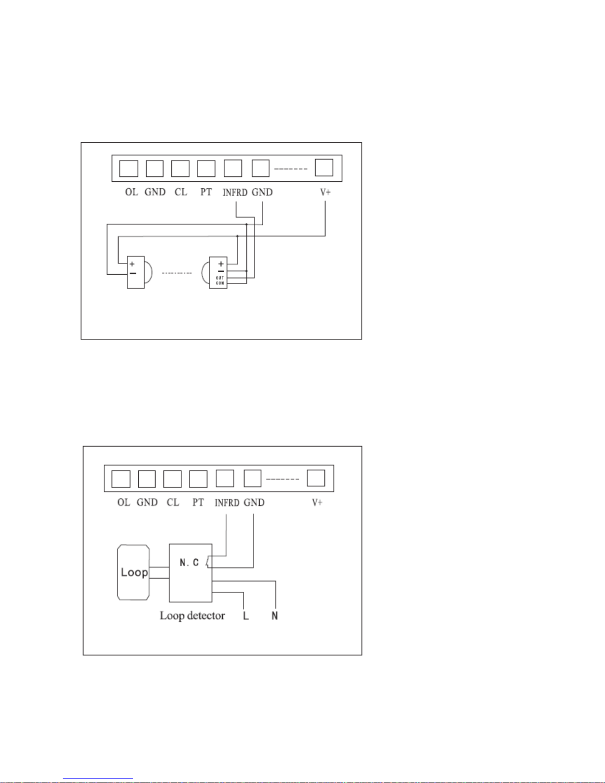
7B.5 Opening Safety Devices
7B.5.1 PHOTOCELLS (NC contact)
- If the infrared beam is obstructed when closing, the barrier immediately reverses
- If the infrared beam is obstructed when opening, the barrier keeps opening.
7B.5.2 LOOP DETECTOR (NC contact)
- If a car enters in the loop’s range when closing, the barrier immediately reverses
- If a car enters in the loop’s range when opening, the barrier keeps opening
Note: If the automatic closing function is on, the barrier automatically closes after a pause time.
The pause time can be set from 1 to 120 seconds.
Transmitter
R
eceiver
(NC)
Page 14
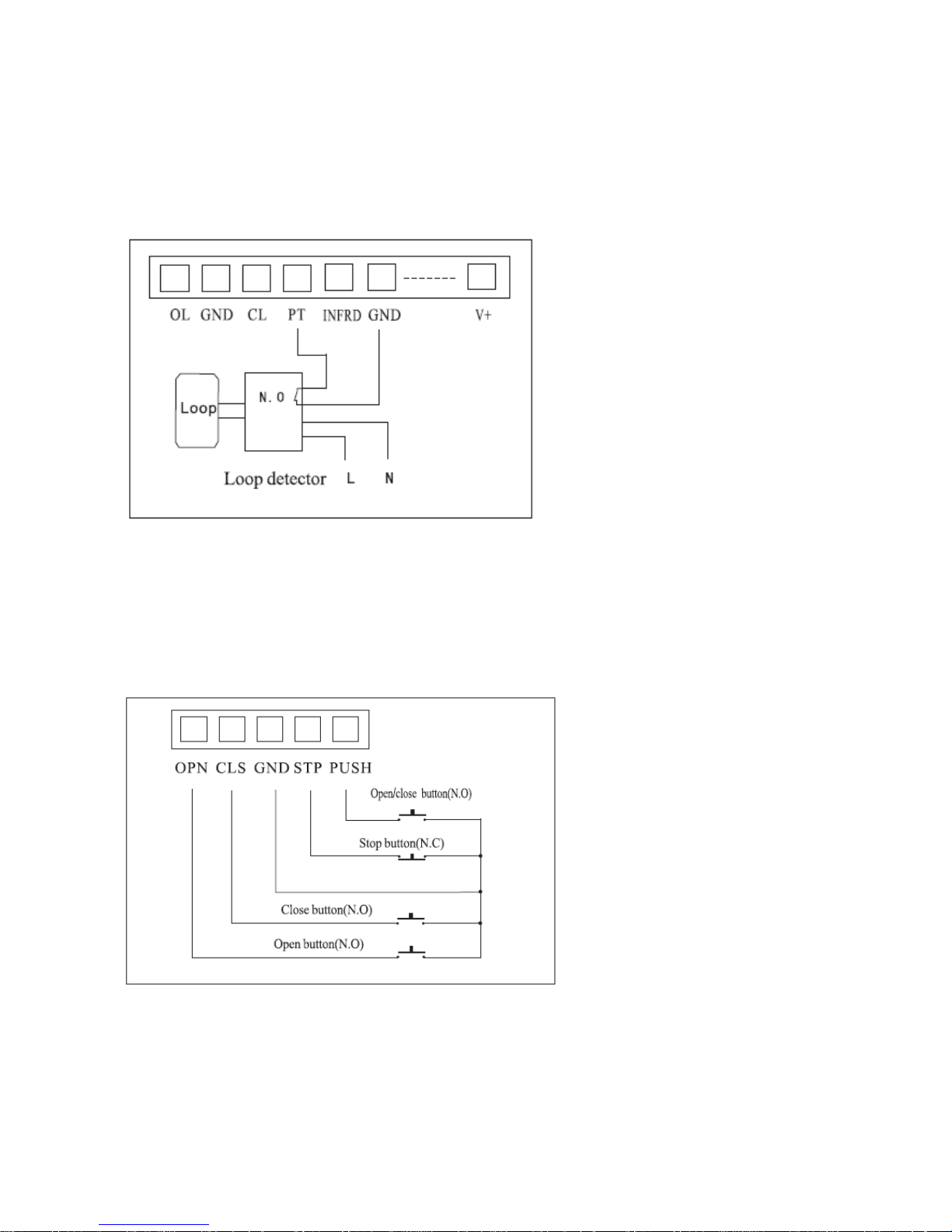
7B.5.3 LOOP DETECTOR (NO contact)
(DIP-switch 1 must be in OFF position)
- If a car stops in the loop’s range, the barrier stays open
- Once the car leaves the loop’s range when opening, the barrier closes
7B.6 External Terminal
When an IC card reader is used, it has to be wired to OPN and GND terminals.
Page 15

8. RADIO PROGRAMMING
8.1 How to program a radio-transmitter
1. Press the button on the receiver card, when the LED lights on release it
2. Press the radio-transmitter’s button you want to use till the light gets off
3. The radio-transmitter is now coded into the receiver.
Additional radio-transmitters can be coded following the same procedure
8.2 How to delete a radio-transmitter
Press the button on the receiver card till the LED lights on and hold it pressed till the light gets off.
Now all radio codes previously learnt have been deleted.
APPENDIX
Balancing springs table
Boom Length Quanty of Springs Spring size
3 -4m 1 Ø 5 x440mm
4.5 – 5 m 2 Ø 4.5 x440mm
Ø 5 x440mm
6m 2 Ø 4.5 x440mm
Ø 5 x440mm
 Loading...