

Page 1

USER’S
MANUAL
PPC-7400
PPC-7402
PPC-7405
PPC-7407
Socket 478 (P4/P4-M)
17”/15”/12.1” Panel PC System
PPC-740X M2
Page 2

Copyright Notice
!
!
PPC-740X Panel PC System
With LCD / Touch screen (optional)
OPERATION MANUAL
COPYRIGHT NOTICE
This operation manual is meant to assist users in installing and setting up the
system. The information contained in this document is subject to change
without prior any notice.
This manual is copyrighted August, 2004. You may not reproduce or
transmit in any form or by any means, electronic, or mechanical, including
photocopying and recording.
ACKNOWLEDGEMENTS
All trademarks and registered trademarks mentioned herein are the property
of their respective owners.
CE NOTICE
This is a class A product. In a domestic environment this product may cause
radio interference in which case the user may be required to take adequate
measures.
Page 3

Copyright Notice
!
FCC NOTICE
This equipment has been tested and found to comply with the limits for a
Class A digital device, pursuant to part 15 of the FCC Rules. These limits are
designed to provide reasonable protection against harmful interference when
the equipment is operated in a commercial environment. This equipment
generates, uses, and can radiate radio frequency energy and, if not installed
and used in accordance with the instruction manual, may cause harmful
interference to radio communications. Operation of this equipment in a
residential area is likely to cause harmful interference in which case the user
will be required to correct the interference at his own expense.
You are cautioned that any change or modifications to the equipment not
expressly approve by the party responsible for compliance could void your
authority to operate such equipment.
!
!
!
!
!
!
* All information contained in this document is subject to change without prior notice.
CAUTION! Danger of explosion if battery is incorrectly replaced. Replace only with the
same or equivalent type recommended by the manufacturer. Dispose of used batteries
according to the manufacturer’s instructions.
WARNING! Some internal parts of the system may have high electrical voltage. And
therefore we strongly recommend that qualified engineers can open and disassemble the
system.
The LCD and touch screen are fragile, please handle them with extra care.
Page 4

Contents
!
TABLE OF CONTENTS
CHAPTER 1 INTRODUCTION
1-1 About This Manual ....................................................... 1-2
1-2 Case Illustration ............................................................. 1-3
1-3 System Specification ..................................................... 1-6
1-4 Safety Precautions ......................................................... 1-12
CHAPTER 2 SYSTEM CONFIGURATION
2-1 Jumper & Connector Quick Reference Table ............... 2-2
2-2 Component Locations ................................................... 2-3
2-3 How to Set the Jumpers ................................................ 2-4
2-4 COM Port Connector ………………………………… 2-6
2-5 COM Port RI & Voltage Selection ……………….….. 2-8
2-6 RS232/422/485 (COM2) Selection …………..….…… 2-12
2-7 VGA Connector ……………………………………….. 2-13
2-8 LVDS Connector ……………………………………… 2-14
2-9 Brightness Voltage Selection …………………………. 2-15
2-10 LCD Panel Voltage Selection ………………………… 2-16
2-11 Power Connector ………………………………………. 2-17
2-12 Floppy Disk Drive Connector ………………………… 2-18
2-13 Hard Disk Drive Connector ………..…………………. 2-19
2-14 Printer Connector ……………………………………… 2-21
2-15 LAN Connector ………………….……………………. 2-22
2-16 LAN LED Connector …...…………………………….. 2-22
2-17 Keyboard Connector ………………………………….. 2-23
2-18 PS/2 Mouse Connector ………………………………… 2-23
2-19 Sound Connector ………………………………………. 2-24
2-20 Reset Connector ……………………………………….. 2-25
2-21 HDD LED Connector ………………………………….. 2-25
2-22 Power Button ………………….…................................ 2-26
2-23 External SMI Connector ………………………………. 2-26
2-24 External Speaker Connector …………………………… 2-26
2-25 Keylock Connector ……………………………………. 2-27
2-26 Clear CMOS Selection ………………………………… 2-27
2-27 USB Connector ……………………………………….. 2-28
2-28 Inverter Connector …………………………………….. 2-29
2-29 Reset/NMI/Clear Watchdog Selection ………………… 2-30
2-30 CPU FAN Connector ………………………………….. 2-31
Page 5

Contents
!
2-31 System FAN Connector ……………………………….. 2-31
2-32 North Chip FAN Connector …………………………… 2-31
2-33 Power LED Connector ………………………………… 2-32
2-34 Memory Installation ............……….............................. 2-32
2-35 P4/ P4-M CPU Selection ……………………………… 2-33
2-36 Digital Input/Output Connector ……………………….. 2-34
2-37 ATX +12V Power Connector …………………………. 2-34
2-38 LVDS Panel Resolution Selection …………………….. 2-35
CHAPTER 3 SOFTWARE UTILITIES
3-1 Introduction ................................................................... 3-2
3-2 VGA Driver Utility ....................................................... 3-3
3-3 Flash BIOS Update ....................................................... 3-4
3-4 LAN Driver Utility ........................................................ 3-6
3-5 Sound Driver Utility .............................…..................... 3-7
3-6 Intel® Chipset Software Installation Utility ………… 3-8
3-7 USB2.0 Chipset Software Installation Utility …………. 3-9
3-8 Touch Screen Driver Utility (Optional) ………..…….. 3-9
3-9 Watchdog Timer Configuration .................................... 3-10
CHAPTER 4 AWARD BIOS SETUP
4-1 Introduction ................................................................... 4-2
4-2 Entering Setup ............................................................... 4-3
4-3 The Standard CMOS Features ….................................. 4-4
4-4 The Advance BIOS Features ….................................... 4-8
4-5 The Advanced Chipset Features ................................... 4-11
4-6 Integrated Peripherals ……........................................... 4-14
4-7 Power Management Setup ……………………………. 4-18
4-8 PNP/PCI Configuration ................................................ 4-20
4-9 PC Health Status …………………………………….. 4-22
4-10 Frequency / Voltage Control ………………………… 4-24
4-11 Load Fail-Safe Defaults ................................................ 4-25
4-12 Load Optimized Defaults .............................................. 4-25
4-13 Password Setting .................................................…...... 4-26
4-14 Save & Exit Setup ......................................................... 4-27
4-15 Exit Without Saving ...................................................... 4-28
Page 6

Contents
!
!
!
APPENDIX A SYSTEM ASSEMBLY
Exploded Diagram for Removing Arm Holder ……………… A-2
Exploded Diagram for Removing Hook Holder ……………… A-3
Exploded Diagram for Removing EXT-Case ………………… A-4
Exploded Diagram for Removing Back Cover ……………….. A-5
Exploded Diagram for Removing LCD Assembly …………. A-6
Exploded Diagram for Front Panel …………………………… A-8
Exploded Diagram for Removing CD-ROM Assembly ……… A-10
Exploded Diagram for Removing HDD Assembly …………… A-11
Exploded Diagram for Removing Output Panel ……………… A-12
Exploded Diagram for Removing Motherboard & Power …… A-13
Exploded Diagram for Removing FDD & CD-ROM ………… A-14
Exploded Diagram for Removing Mask ………………………. A-16
Exploded Diagram for Wall Mounting ……………………….. A-17
APPENDIX B TECHNICAL SUMMARY
Block Diagram ......................................................................... B-2
Interrupt Map ........................................................................... B-3
RTC & CMOS RAM Map ....................................................... B-4
Timer & DMA Channels Map .................................................. B-5
I/O & Memory Map ................................................................. B-6
Page 7

!
Page:1-1
!
!
!
!
INTRODUCTION
!
!
!
!
This chapter gives you the information for PPC-740X. It also
outlines the System specifications.
Section includes:
z About This Manual
z Case Illustration
z System Specifications
z Safety precautions
Experienced users can skip to chapter 2 on page 2-1
for a Quick Start.
CHAPTER
1!
Page 8

Chapter 1 Introduction
!
Page: 1-2
PPC-740X USER
c
S MANUAL
1-1. ABOUT THIS MANUAL
!
Thank you for purchasing our Panel PC. It is an updated system designed to be
comparable with the highest performance of IBM AT personal computers. It
provides faster processing speed, greater expandability, and can handle more
tasks. This manual is designed to assist you on how to make the proper
installation to set up the system. It contains five chapters. The user can use
this manual for configuration according to the following chapters :
Chapter 1 Introduction
This chapter introduces you to the background of this manual, illustration of
the case, and the specifications for this system. The final page of this chapter
indicates some safety reminders on how to take care of your system.
Chapter 2 System Configuration
This chapter outlines the Prox-7400 components' locations and their functions.
In the end of this chapter, you will learn how to set jumper and how to
configure the system for your own needs.
Chapter 3 Software Utilities
This chapter contains helpful information for proper installations of the VGA
utility, LAN utility, Sound utility and Flash BIOS update. It also describes
the function of the Watchdog Timer.
Chapter 4 Award BIOS Setup
This chapter indicates on how to set up the BIOS configurations.
Appendix A System Assembly
This section gives you the exploded diagram for the whole system unit.
Appendix B Technical Summary
This section gives you the information about the Technical maps.
Page 9
Chapter 1 Introduction
!
PPC-740X USERcS MANUAL
Page: 1-3
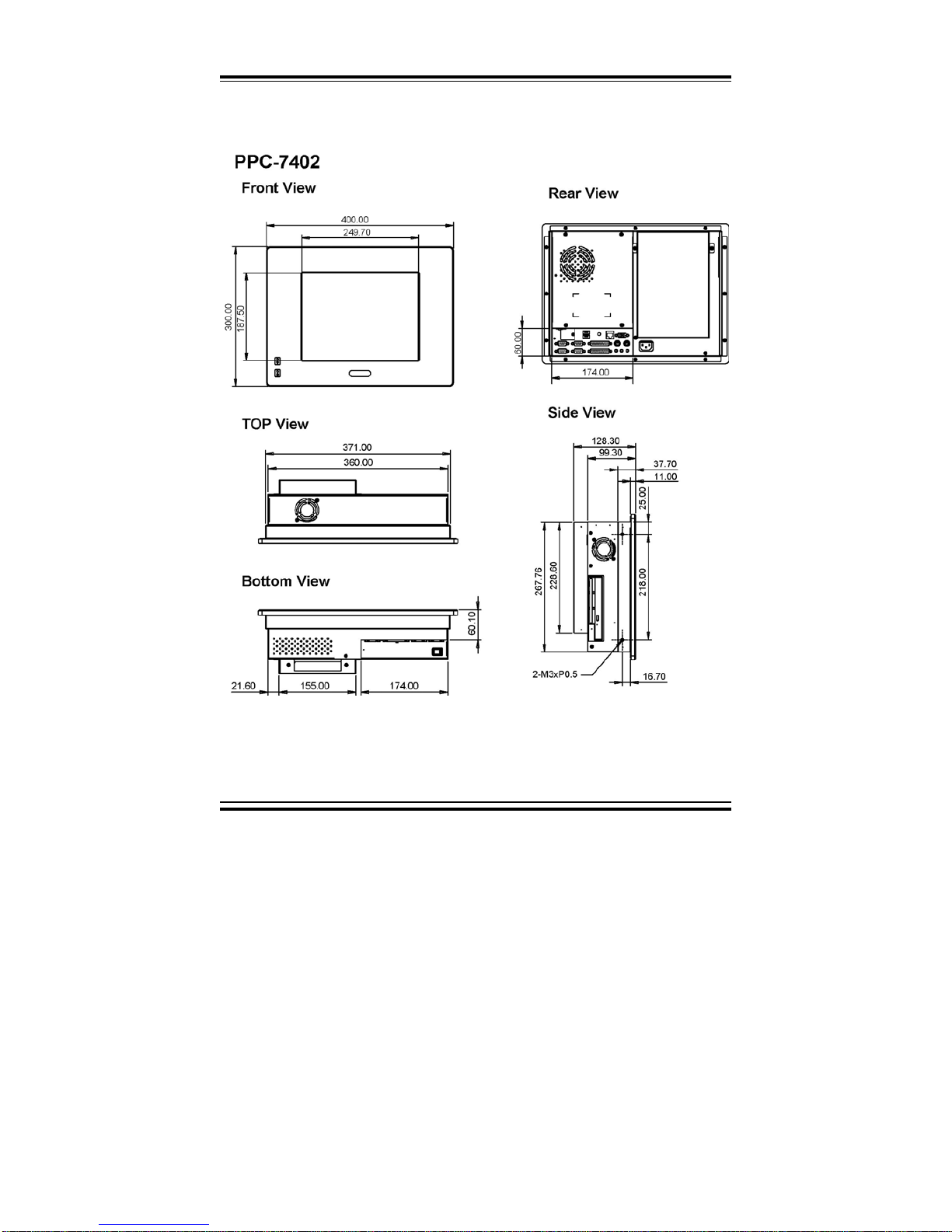
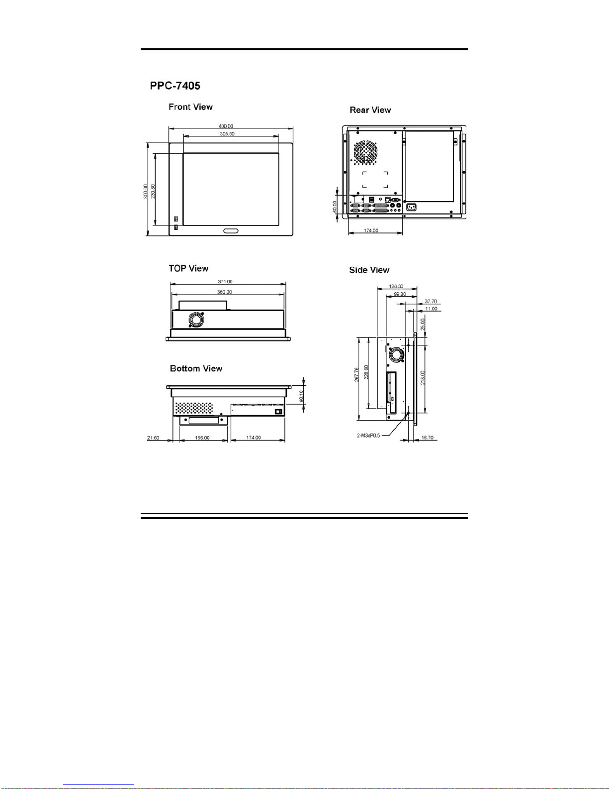
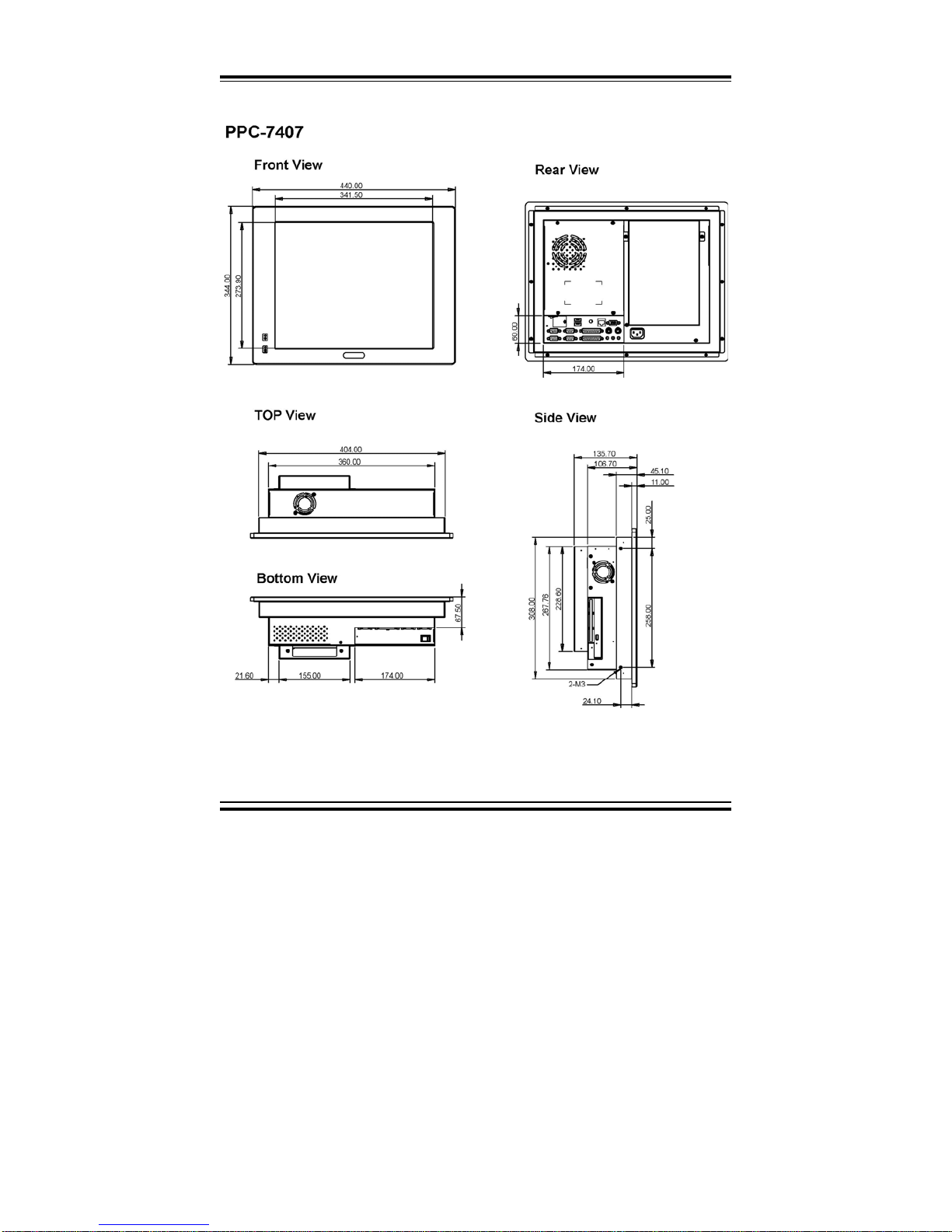
1-2. CASE ILLUSTRATION
!
!
!
!
!
Page 10
Chapter 1 Introduction
!
Page: 1-4
PPC-740X USER
c
S MANUAL
!
Page 11
Chapter 1 Introduction
!
PPC-740X USERcS MANUAL
Page: 1-5
Page 12

Chapter 1 Introduction
!
Page: 1-6
PPC-740X USER
c
S MANUAL
1-3. SYSTEM SPECIFICATIONS
MAINBOARD (PROX-7400)
z CPU TYPE:
Intel® Pentium® 4/Pentium® 4-M/Intel® Celeron/ Mobile processors
CPU Frequency 2.0~2.8GHz
Auto detect voltage regulator.
z CHIPSET:
Intel® 845GV
z MEMORY :
Up to 1GB DDR SDRAM
One 184-pin DIMM sockets on board.
z CACHE :
Built-in CPU(128/256KB Cache).
z REAL-TIME CLOCK :
CR2023 battery backed CMOS RAM
Hardware implementation to indicate century rollover.
z BIOS :
Phoenix-Award Flash BIOS for plug & play function.
Memory size with 4MB and with VGA BIOS.
Support S I/O Setup.
z KEYBOARD CONNECTOR :
Mini DIN connector.
Supports PC/AT Keyboard.
z MOUSE CONNECTOR :
Mini DIN connector.
Supports PS/2 Mouse.
Page 13

Chapter 1 Introduction
!
PPC-740X USERcS MANUAL
Page: 1-7
z SSD SOCKET (OPTIONAL) :
One 32-pin socket.
Supports Disk-on-chip up to 576MB.
z BUS SUPPORT :
External PCI Bus (Riser card support 1P1I/3P3I).
z VGA :
Integrated in 845GV, supports CRT & TFT-LCD panel. LCD panel
connector on board for LVDS panel (7305), 15-Pin VGA D-sub connector
on rear panel. Supports LCD backlight turn off function. Chrontel CH7305
supports 18/24-bit 2 channel LVDS panel or CH7304 (Pin-to-pin compatible
to CH7305) supports 18/24-bit 1 channel LVDS panel. ( 20-pin pin header X
2 on-board.)
z WATCHDOG :
I / O port 443H to Enable watchdog.
I / O port 441H to Disable watchdog.
Selectable for NMI or Reset function.
Time-out timing select 0 / 8 / 16 / 24 / 32 / 40 / 48 / 56 / 64 / 72 / 80 / 88 /
96 / 104 / 112 / 120 sec +/- 25%.
z IDE INTERFACE :
Two IDE port, support for Ultra ATA-33/66/100.
Support up to four IDE devices.
z FLOPPY DISK DRIVE INTERFACE :
One 26-pin connector.
Support for slim Floppy Disk Drive.
z SERIAL PORT :
Four high speed 16550 Compatible UARTs with Send / Receive 16 Byte
FIFOs.
COM1 (D-Sub Connector) for RS-232;
COM2 (D-Sub Connector) for RS-232/422/485;
COM3 (D-Sub Connector) for RS-232
COM4 (D-Sub Connector) for RS-232.
Page 14

Chapter 1 Introduction
!
Page: 1-8
PPC-740X USER
c
S MANUAL
COM1/2/3/4 contain 5V or 12V power capability with 9-pin D-sub
connector on rear panel. COM4 with 9-pin box-header available for
touch panel installed.
z PARALLEL PORT :
One 25-pin D-Sub connector on rear panel.
Support for SPP, ECP, EPP Function.
Bi-directional parallel port.
z LAN ADAPTER :
Intel® 82541 chip.
RJ-45 jack onboard, Support for 10/100/1000 mbps Ethernet.
Support Wake-On-LAN function.
z USB CONNECTOR :
Two USB ports on rear panel.
One internal USB port for touch panel.
Complies with USB Spec Rev 2.0.
z SOUND :
RealTek ALC202A , AC’ 97 Codec. The signal of MIC-in, Line-in, Lineout connectors on rear panel and CD audio-in designed in as a standard
connector.
z HARDWARE MONITORING FUNCTION :
Monitor CPU Voltage, CPU Temperature and Cooling Fan.
z LED INDICATOR :
System power.
HDD Read/write.
z DMA CONTROLLER :
82C37 x 2
z DMA CHANNELS :
7
z INTERRUPT CONTROLLERS :
82C59 x 2
Page 15

Chapter 1 Introduction
!
PPC-740X USERcS MANUAL
Page: 1-9
z INTERRUPT LEVELS :
15
LCD PANEL
TFT color LCD is manufactured by using very high brightness technology.
Some sequential pixels may not light or may light always, but this is not a
failure.
z LCD TYPE :
LCD Panel 12.1”: Priority source - Mitsubishi (1 LVDS) or similar model.
LCD Panel 15” : Priority source - AU (1 LVDS) or similar model.
LCD Panel 17” : Priority source - AU (2 LVDS) or similar model.
z PIXEL PITCH :
According to the supplier’s LCD specification.
z BRIGHTNESS :
According to the supplier’s LCD specification.
z CONTRAST RATIO :
According to the supplier’s LCD specification.
z POWER CONSUMPTION :
According to the supplier’s LCD specification.
z VIEWING ANGLE :
According to the supplier’s LCD specification.
z RESPONSE TIME :
According to the supplier’s LCD specification.
z COLOR :
According to the supplier’s LCD specification.
z LCD MTBF :
According to the supplier’s LCD specification.
z BACKLIGHT MTBF :
Page 16

Chapter 1 Introduction
!
Page: 1-10
PPC-740X USER
c
S MANUAL
According to the supplier’s LCD specification.
z DIMENSION :
According to the supplier’s LCD specification.
TOUCH SCREEN : (OPTIONAL)
Vendor
Liyi Fuji
Type Resistive
Static Load
500g (30 с , 30 Sec)
N/A
Hardness 3H
Transparency 82% 80%
Write Life 10,000,000 Times 1,000,000 Words
Knock Life 35,000,000 Times 10,000,000 Times
Chattering Time 10 ms 10 ms
Input Voltage 5V 5V
Wire 5 Wire 7 Wire
GENERAL INFORMATION
z POWER SUPPLY :
AC Power: 200 watt ATX Power Supply
Input Requirement:
- The power supply shall operate from 90 to 132 Vrms or 180 to 264 Vrms.
- The power supply shall operate from an AC mains frequency of 47
through 63Hz.
- The Ac mains single-cycle peak inrush current shall be limited to 50
amps cold, 80 amps warm measured at 115Vrms, 60Hz and coinciding
with the AC main voltage peak.
- The Ac mains steady-state RMS input current shall be:
4.0amps maximun/115Vrms, 60Hz.
2.0ampx maximum/230Vrms, 50Hz/
2
Page 17

Chapter 1 Introduction
!
PPC-740X USERcS MANUAL
Page: 1-11
Output Requirements:
! Njojnvn!
Mpbe!
Nbyjnvn!
Mpbe!
Mpbe!Sfr/ Mjof!Sfh/ Sjqqmf!'!
Opjtf!
,4/4W! 1/4B! 27/9B! ²6&! ²2&! 61nW!Q.Q!
,6W! 1/4B! 23B! ²6&! ²2&! 61nW!Q.Q!
,23W! 2/6B! 21B! ²6&! ²2&! !
.23W! 1/1B! 1/9B! ²21&! ²2&! !
,6Wtc! 1/1B! 3/1B! ²6&! ²2&! 61nW!Q.Q!
(1) +3.3V & +5V total output shall not exceed 70W, and the total output
for this subject power supply is 200W.
(2) All outputs shall be safety-isolated from the AC mains and share a
common return. This common return must be connected to supply
chassis.
(3) Voltages and ripple are measured at the load side of mating connectors
with a 0.1uF monolithic ceramic capacitor paralleled by a 10uF
electrolytic capacitor across the measuring terminals.
Dimension: 80mm x 130mm x 40mm
z DRIVE BAYS (Optional) :
One 3.5” HDD, one slim FDD, and one slim CD-ROM
z EXPANSION SLOTS :
PCI slot for Riser Card use.
z CONSTRUCTION :
Electo Galvanized steel chassis.
Aluminium front bezel.
z DIMENSIONS :
CASE:
PPC-7402/7405: 400 x 300 x 123mm (15.75” x 11.81” x 4.85”)
PPC-7407: 440 x 344 x 123mm (17.32” x 13.54” x 4.85”)
z NET WEIGHT :
9.5kg (20.9lb) ~ 11kg (24.2lb)
Page 18

Chapter 1 Introduction
!
Page: 1-12
PPC-740X USER
c
S MANUAL
1-4. SAFETY PRECAUTIONS
Following messages are safety reminders on how to protect your systems from
damages. And thus, helps you lengthen the life cycle of the system.
1. Check the Line Voltage
a. The operating voltage for the power supply should cover the range of
100VAC-240VAC, otherwise the system may be damaged.
2. Environmental Conditions
a. Place your PPC on a sturdy, level surface. Be sure to allow enough room
on each side to have easy access.
b. Avoid extremely hot or cold places to install your PPC.
c. Avoid exposure to sunlight for a long period of time (for example in a
closed car in summer time. Also avoid the system from any heating
device.). Or do not use PPC when it‘s been left outdoors in a cold winter
day.
d. Bear in mind that the operating ambient temperature is from 0qC up to
+40qC.
e. Avoid moving the system rapidly from a hot place to a cold place or vice
versa because condensation may come from inside of the system.
f. Place PPC against strong vibrations, which may cause hard disk failure.
g. Do not place the system too close to any radio active device. Radioactive
device may cause interference.
3. Handling
a. Avoid putting heavy objects on top of the system.
b. Do not turn the system upside down. This may cause the floppy drive
and hard drive to mal-function.
c. Do not remove the diskette from the Floppy drive while the light is still
on. If you remove the diskette while the light is on, you may damage
the information on the diskette.
4. Good Care
a. When the outside of the case is stained, remove the stain with neutral
washing agent with a dry cloth.
b. Never use strong agents such as benzene and thinner to clean the system.
c. If heavy stains are present, moisten a cloth with diluted neutral washing
agent or with alcohol and then wipe thoroughly with a dry cloth.
d. If dust has been accumulated on the outside, remove it by using a special
made vacuum cleaner for computers.
Page 19

Page 2-1
SYSTEM
CONFIGURATION
Helpful information that describes the jumper & connector settings,
and component locations.
Section includes:
z Jumper & Connector Quick Reference Table
z Component Locations
z Configuration and Jumper settings
z Connector Pin Assignments
CHAPTER
2
Page 20

Chapter 2 Hardware Configuration
Page: 2-2
PPC-740X USER
’S MANUAL
2-1. JUMPER & CONNECTOR QUICK REFERENCE TABLE
COM Port Connector ……………………………………....
………………………………………
COM1, COM2
COM3, COM4
COM Port RI & Voltage Selection ……………………… JP8
RS232/422/485 (COM2) Selection .....................…………. JP9
VGA Connector …………………………………………… VGA1
LVDS Connector ...............................................………….. LVDS1, LVDS2
Brightness Voltage Selection ……………………..…….. JP11
LCD Panel Voltage Selection …………………………….. JP3
Power Connector …………………………………………. ATX1
Floppy Disk Drive Connector …..........................………… FDD1
Hard Disk Drive Connector ….............................………… IDE1, IDE2
Printer Connector …………………………………………. LPT1
LAN Connector ….......................…....................………… LAN1
LAN LED Connector ……………………………………… LANLED1
Keyboard Connector ……………………………………… KB1
PS/2 Mouse Connec
t
or ……...........................……………. MS1
Sound Connector ………………………………………….. LINE1, MIC1, SPK1, CDIN1
Reset Connector …............................................………….. JP10 (9-10)
HDD LED Connector …………………………………….. HDLED1
Power Button …………………….……………………….. PWBN
External SMI Connector …………………………………. JP10 (5-7)
External Speaker Connector …………………………….. JP10 (2,4,6,8)
Keylock Connector ………………………………………. JP10 (1,3)
CMOS Function Selection ………………………………… JP4
USB Connector …………………………………………… USB1, USB2, USB3, USB4
Reset/NMI/Clear Watchdog Selection ……….…………… JP6
CPU FAN Connector ……………………………………… CPUFAN
System FAN Connector ………………………………….. SYSFAN
North Chip FAN Connector ……………………………… NB_FAN
Power LED Connector ……………………………………. PWLED1
Memory Installation ……..................................…..……… DIMM1
P4/P4-M CPU Selection …………………………………. JP1
Digital Input/Output Connector ………………………….. DIO1
ATX +12V Power Connector …………………………. CN1
Inverter Connector ……………………………………. CN2
LVDS Panel Resolution Selection ……………………. JP2
Reserved Pin ……………………………………………… JP7, CN3
Page 21
Chapter 2 Hardware Configuration
PPC-740X USER’S MANUAL
Page: 2-3
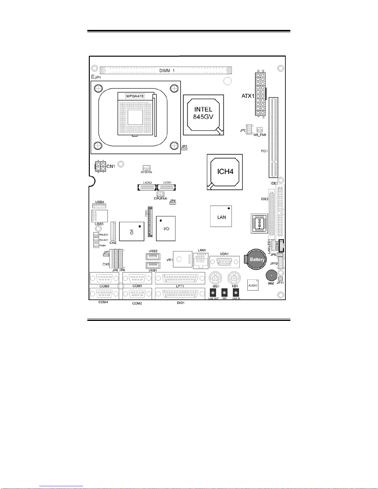
2-2. COMPONENT LOCATIONS
PPC-740X Connector, Jumper and Component locations
Page 22
Chapter 2 Hardware Configuration
Page: 2-4
PPC-740X USER
’S MANUAL
2-3. HOW TO SET THE JUMPERS
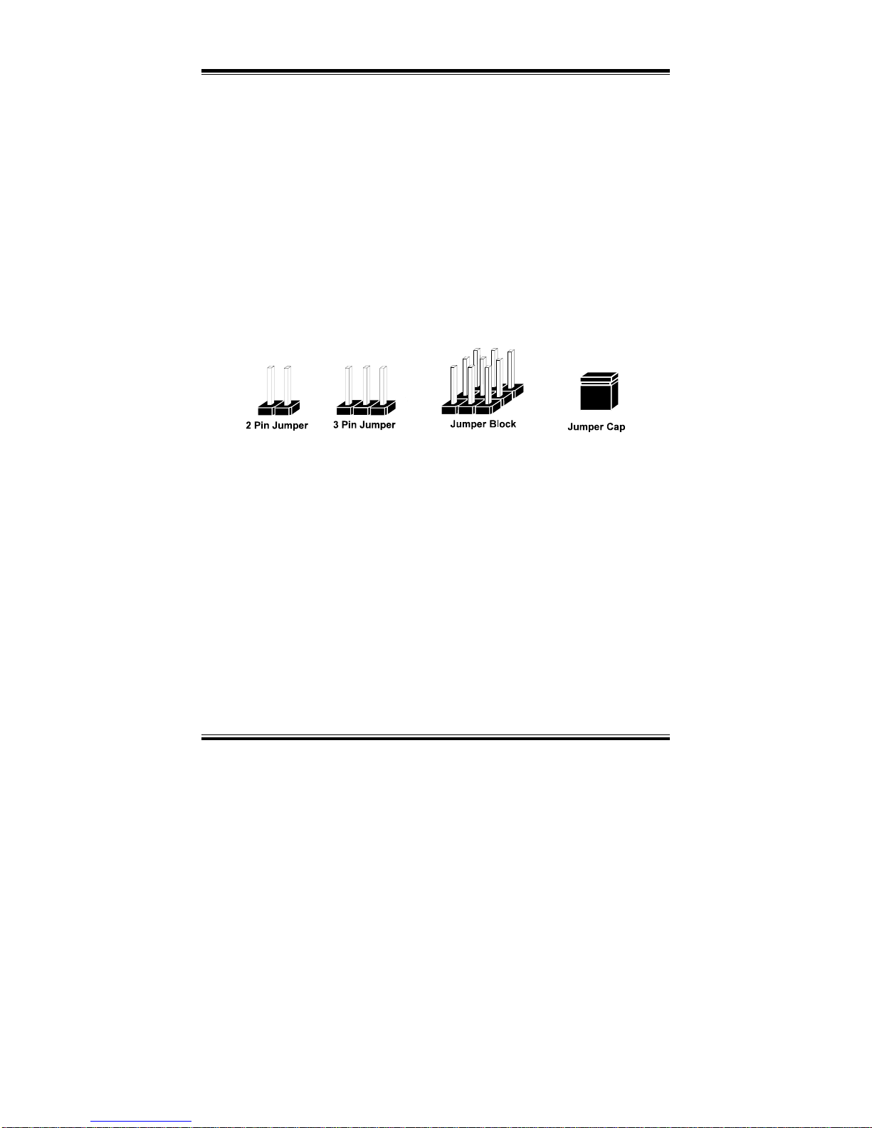
You can configure your board by setting the jumpers. Jumper is consists of
two or three metal pins with a plastic base mounted on the card, and by
using a small plastic "cap", Also known as the jumper cap (with a metal
contact inside), you are able to connect the pins. So you can set-up your
hardware configuration by "opening" or "closing" pins.
The jumper can be combined into sets that called jumper blocks. When the
jumpers are all in the block, you have to put them together to set up the
hardware configuration. The figure below shows how this looks like.
JUMPERS AND CAPS
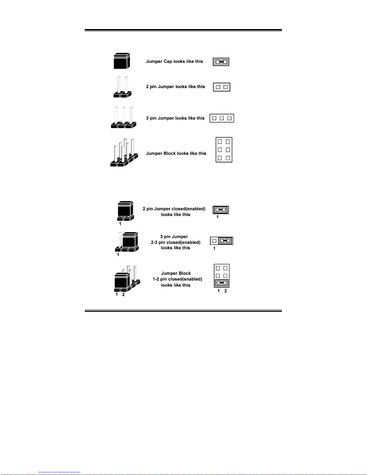
If a jumper has three pins for example, labelled PIN1, PIN2, and PIN3. You
can connect PIN1 & PIN2 to create one setting and shorting. You can either
connect PIN2 & PIN3 to create another setting. The same jumper diagrams
are applied all through this manual. The figure below shows what the manual
diagrams look and what they represent.
Page 23
Chapter 2 Hardware Configuration
PPC-740X USER’S MANUAL
Page: 2-5
JUMPER DIAGRAMS
JUMPER SETTINGS
Page 24
Chapter 2 Hardware Configuration
Page: 2-6
PPC-740X USER
’S MANUAL
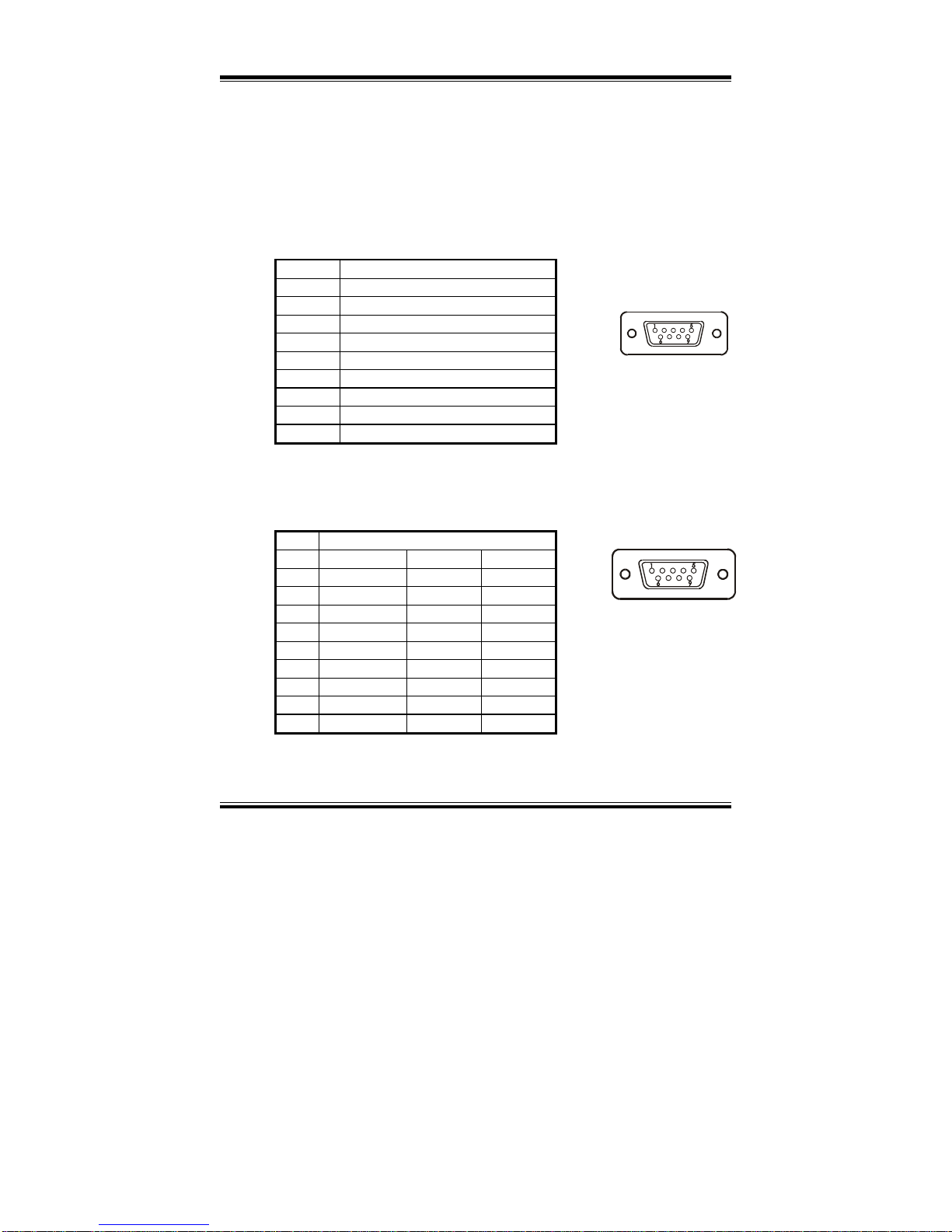
2-4. COM PORT CONNECTOR
There are four COM ports enhanced in this board namely: COM1,
COM2, COM3 and COM4. COM1, COM3 and COM4 are fixed for
RS-232, while COM2 is selectable for RS-232/422/485.
COM1 : COM1 Connector
The COM1 Connector assignments are as follows :
PIN ASSIGNMENT
1 NDCDA
2 NSINA
3 NSOUTA
4 NDTRA
5 GND
6 NDSRA
7 NRTSA
8 NCTSA
9 RIN1
COM2 : COM2 Connector
The COM2 Connector assignments are as follows :
PIN ASSIGNMENT
RS-232 RS-422 RS-485
1 NDCDB TX- TX2 NSINB TX+ TX+
3 NSOUTB RX+ RX+
4 NDTRB RX- RX5 GND GND GND
6 NDSRB RTS- NC
7 NRTSB RTS+ NC
8 NCTSB CTS+ NC
9
RIN2
CTS- NC
COM1
COM2
Page 25
Chapter 2 Hardware Configuration
PPC-740X USER’S MANUAL
Page: 2-7
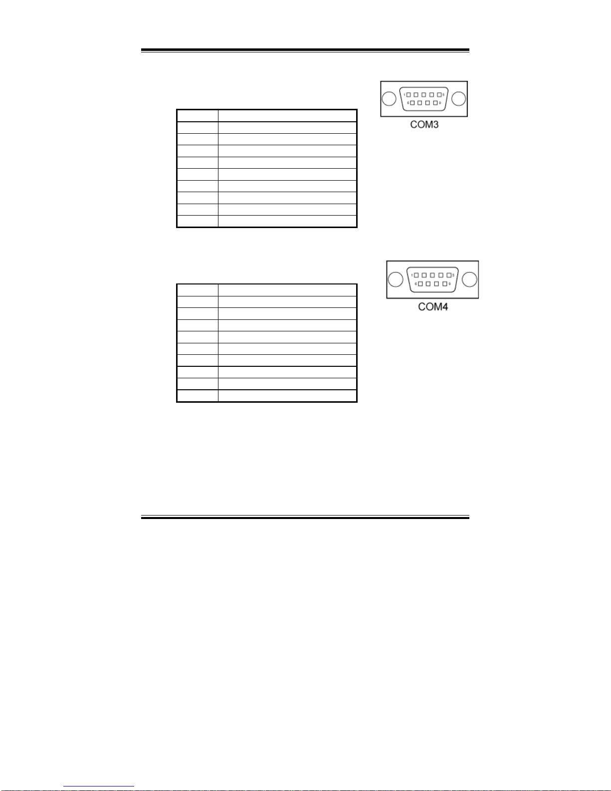
COM3 : COM3 Connector
The pin assignments are as follows :
PIN ASSIGNMENT
1 NDCDC
2 NSINC
3 NSOUTC
4 NDTRC
5 GND
6 NDSRC
7 NRTSC
8 NCTSC
9 RIN3
COM4 : COM4 Connector
The pin assignments are as follows :
PIN ASSIGNMENT
1 NDCDD
2 NSIND
3 NSOUTD
4 NDTRD
5 GND
6 NDSRD
7 NRTSD
8 NCTSD
9 RIN4
All COM port’s pin 9 is selectable for RI, +5V or +12V. For
more information, please refer to our “COM RI and Voltage
Selection”
Page 26
Chapter 2 Hardware Configuration
Page: 2-8
PPC-740X USER
’S MANUAL
2-5. COM PORT RI & VOLTAGE SELECTION
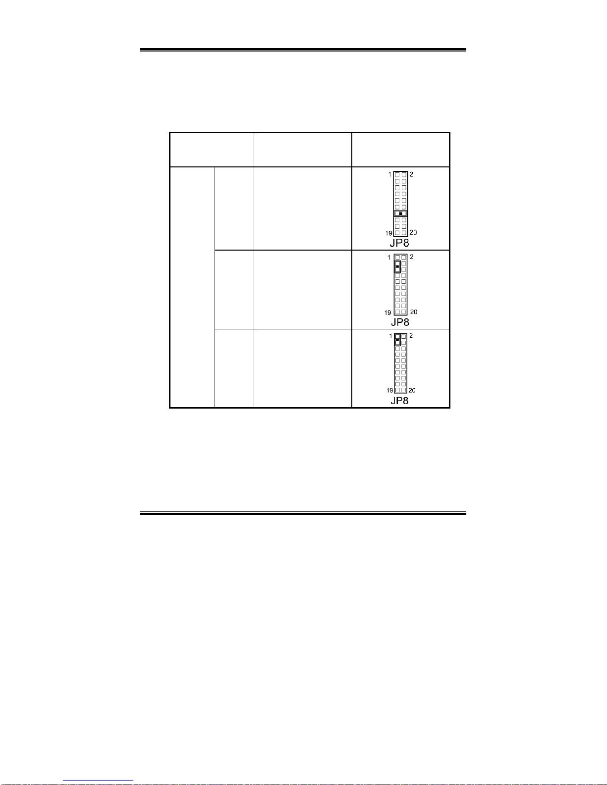
JP8 : COM1, COM2, COM3, and COM4 RI & Voltage Selection
The selections are as follows:
SELECTION
JUMPER SETTING
(Pin Closed)
JUMPER
ILLUSTRATION
RI
13-14
5V
3-5
COM1
(Max. 1A)
12V
1-3
Page 27
Chapter 2 Hardware Configuration
PPC-740X USER’S MANUAL
Page: 2-9
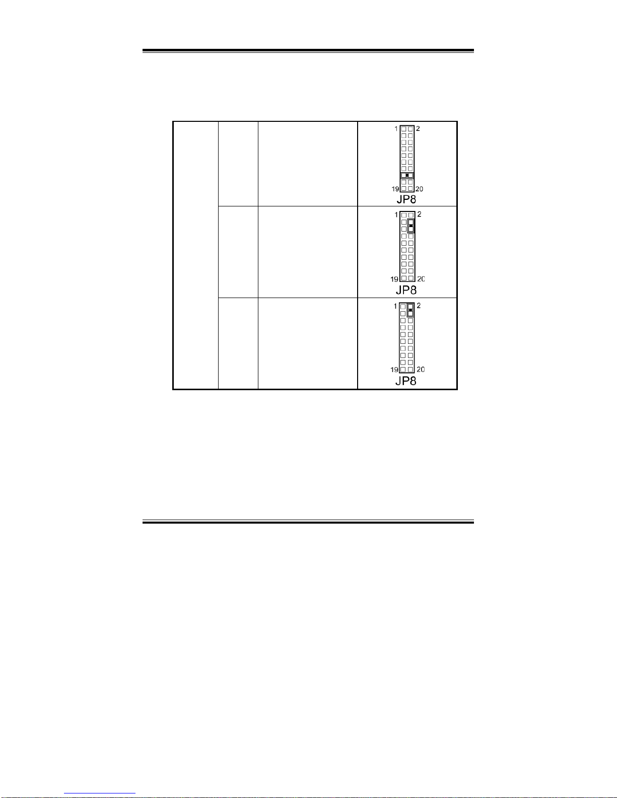
RI
15-16
5V
4-6
COM2
(Max. 1A)
12V
2-4
Page 28
Chapter 2 Hardware Configuration
Page: 2-10
PPC-740X USER
’S MANUAL
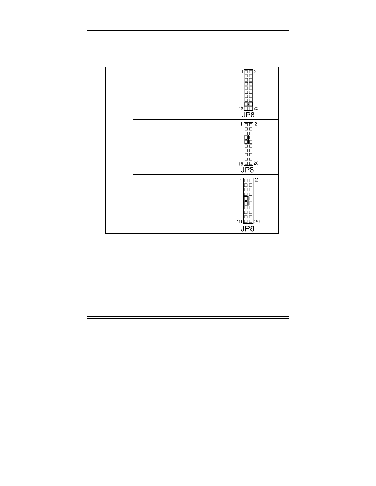
RI
17-18
5V
7-9
COM3
(Max. 1A)
12V
9-11
Page 29
Chapter 2 Hardware Configuration
PPC-740X USER’S MANUAL
Page: 2-11
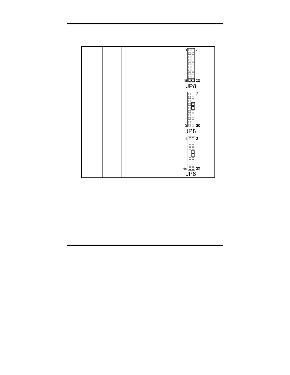
RI
19-20
5V
8-10
COM4
(Max. 1A)
12V
10-12
Page 30
Chapter 2 Hardware Configuration
Page: 2-12
PPC-740X USER
’S MANUAL
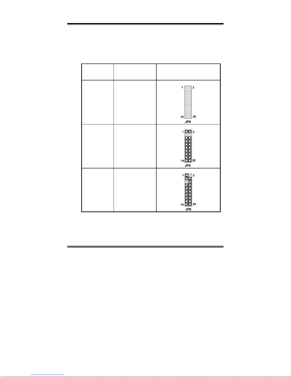
2-6. RS232/422/485 (COM2) SELECTION
JP9 : RS-232/422/485 (COM2) Selection
COM2 is selectable for RS-232, 422, 485 function.
The jumper settings are as follows :
COM 2
FUNCTION
JUMPER SETTING
(pin closed)
JUMPER ILLUSTRATION
RS-232 Open
RS-422
1-2, 5-6, 7-8, 9-10
11-12, 13-14, 15-16
17-18, 19-20
RS-485
1-3, 4-6, 7-8, 9-10
11-12, 13-14, 15-16
17-18, 19-20
*** Manufactory default --- RS-232.
Page 31
Chapter 2 Hardware Configuration
PPC-740X USER’S MANUAL
Page: 2-13
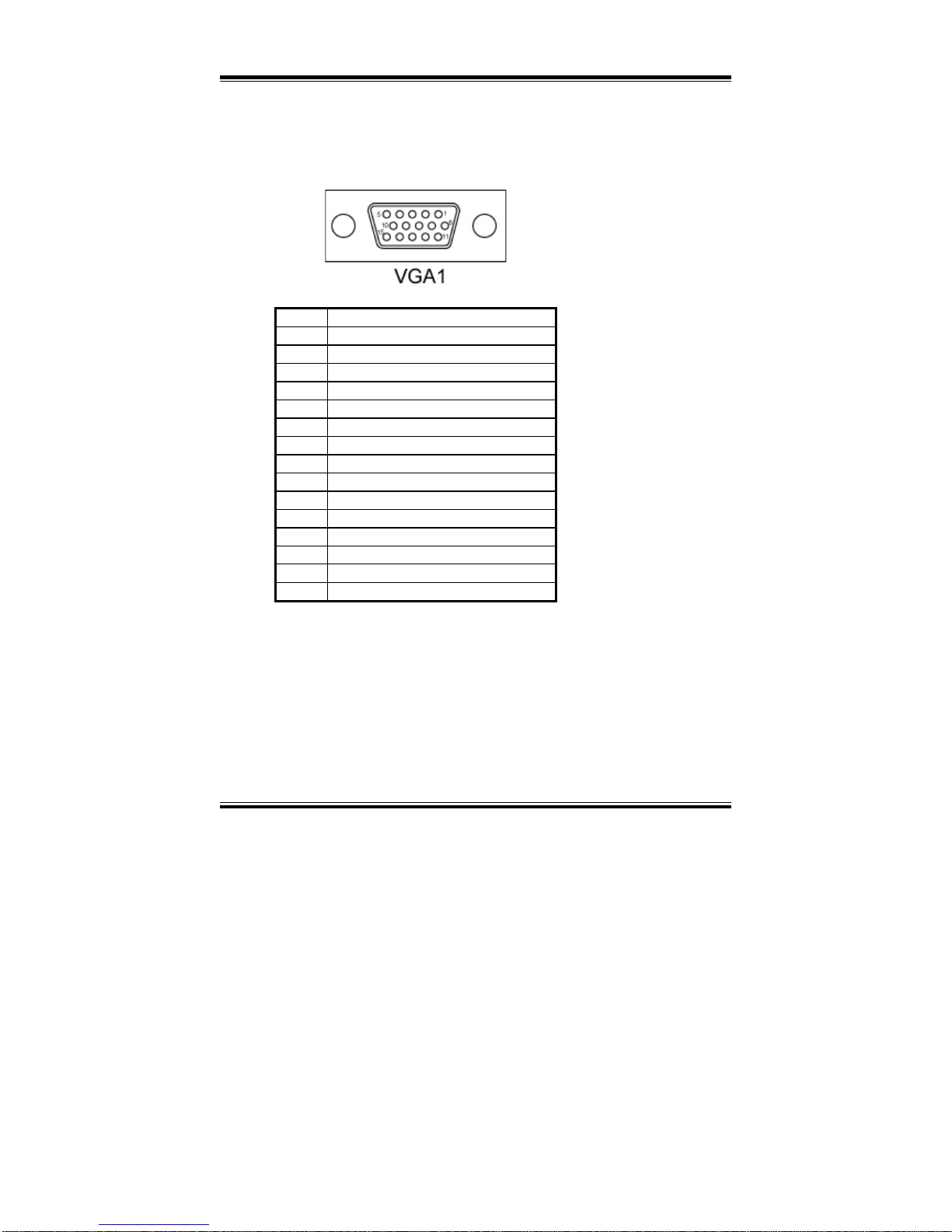
2-7. VGA CONNECTOR
VGA : VGA Connector
The pin assignments are as follows:
PIN ASSIGNMENT
1 VGA_RED
2 VGA_GREEN
3 VGA_BLUE
4 NC
5 GND
6 GND
7 GND
8 GND
9 VCC (Max. 1A)
10 GND
11 NC
12 VGA_VDDA
13 VGA_HSYNC_5V
14 VGA_VSYNC_5V
15 VGA_VDDCLK
Page 32
Chapter 2 Hardware Configuration
Page: 2-14
PPC-740X USER
’S MANUAL
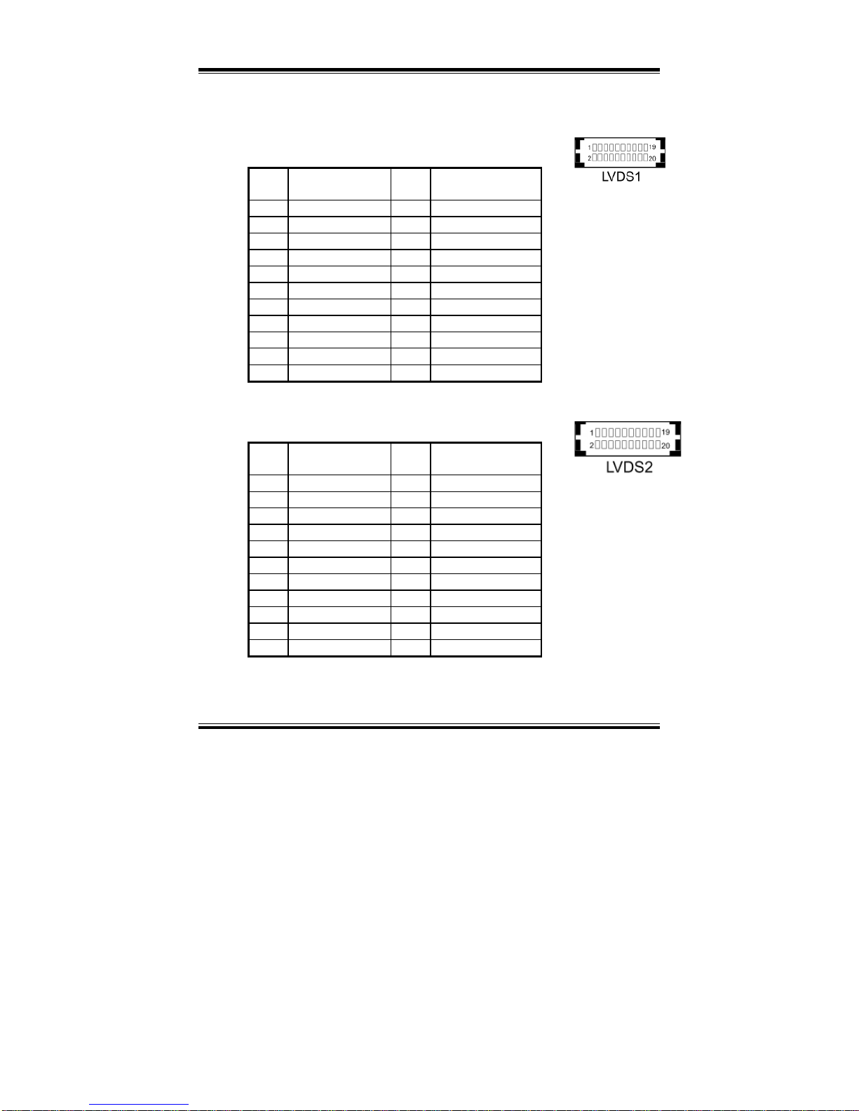
2-8. LVDS CONNECTOR
LVDS1 : LVDS Connector
The pin assignments are as follows :
PIN ASSIGNMENTPIN ASSIGNMENT
1 GND 12 JCKL1M
2 GND 13 GND
3 JA2P 14 GND
4 JA3P 15 JA0P
5 JA2M 16 GND
6 JA3M 17 JA0M
7 GND 18 LPVDD
8 GND 19 GND
9 JA1P 20 LPVDD
10 JCLK1P
11 JA1M
LVDS2 : LVDS Connector
The pin assignments are as follows :
PIN ASSIGNMENTPIN ASSIGNMENT
1 GND 12 JCLK2M
2 GND 13 GND
3 JA6P 14 GND
4 JA7P 15 JA4P
5 JA6M 16 GND
6 JA7M 17 JA4M
7 GND 18 LPVDD
8 GND 19 GND
9 JA5P 20 LPVDD
10 JCLK2P
11 JA5M
Page 33
Chapter 2 Hardware Configuration
PPC-740X USER’S MANUAL
Page: 2-15
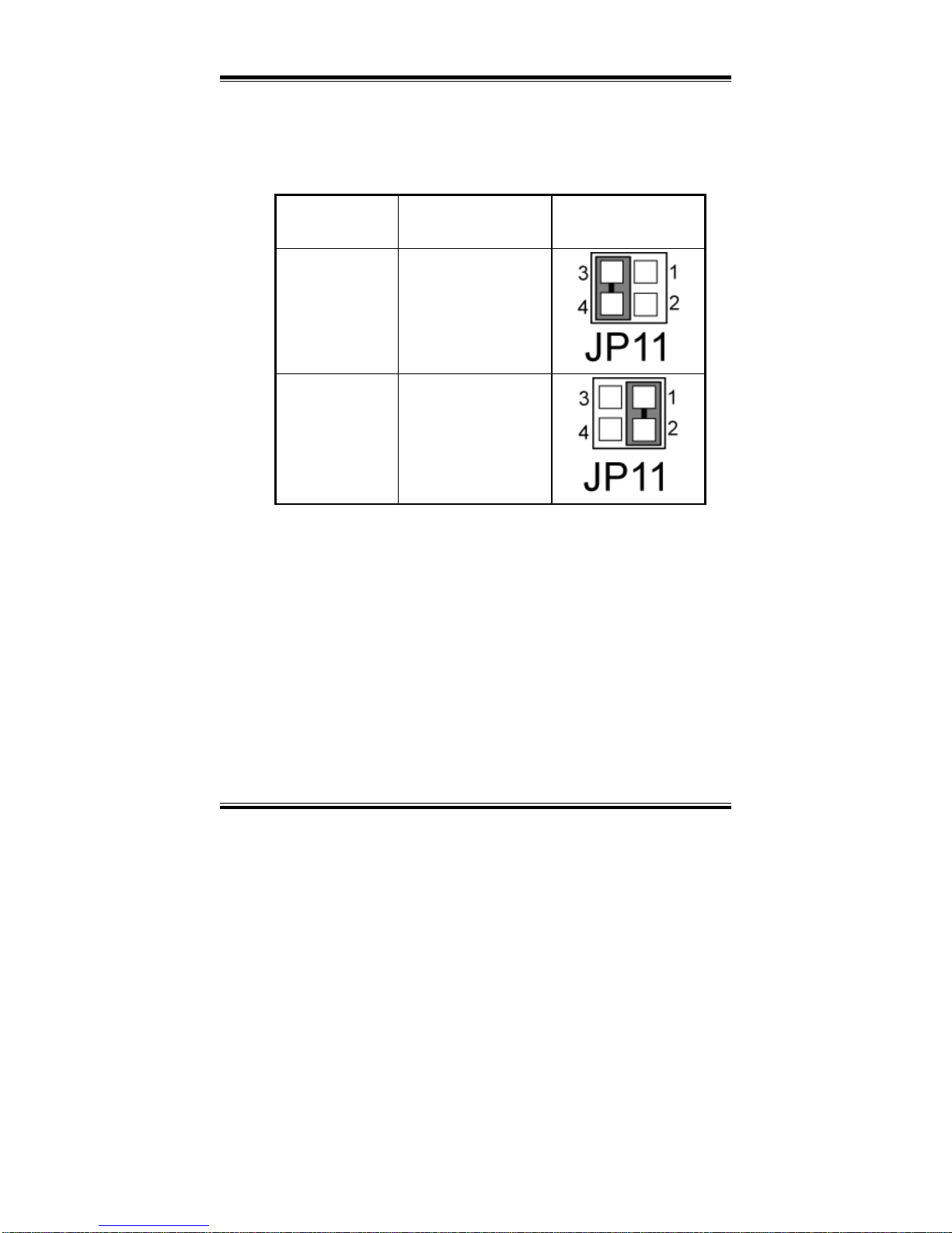
2-9. BRIGHTNESS VOLTAGE SELECTION
JP11 : Brightness Voltage Selection
The selections are as follows :
SELECTION
JUMPER SETTING
(Pin Closed)
JUMPER
ILLUSTRATION
5V
3-4
2.5V
1-2
***Manufacturing Default is set as 5V.
Page 34
Chapter 2 Hardware Configuration
Page: 2-16
PPC-740X USER
’S MANUAL
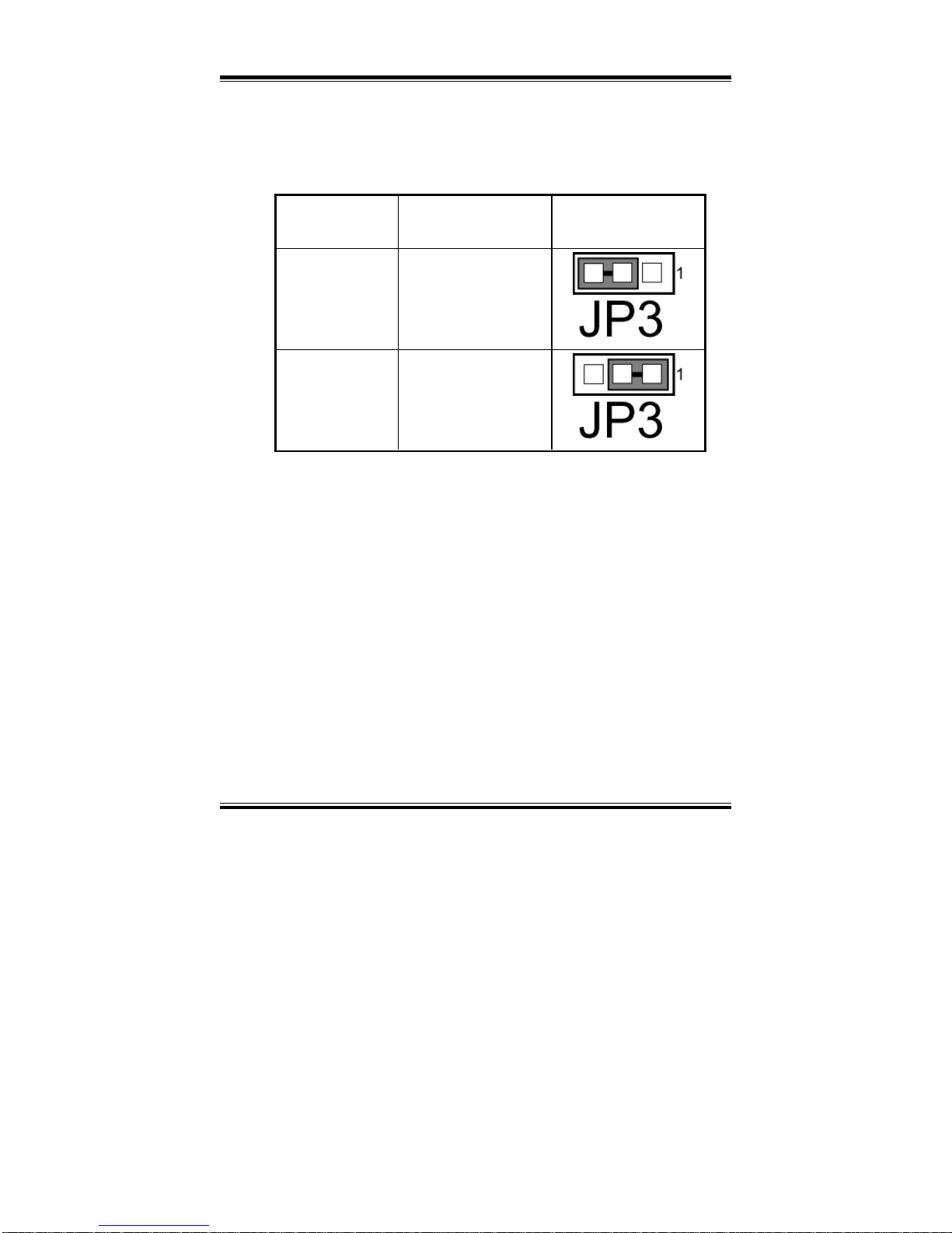
2-10. LCD PANEL VOLTAGE SELECTION
JP3: LCD Panel Voltage Selection
The selections are as follows :
SELECTION
JUMPER SETTING
(Pin Closed)
JUMPER
ILLUSTRATION
3.3V
2-3
5V
1-2
Page 35
Chapter 2 Hardware Configuration
PPC-740X USER’S MANUAL
Page: 2-17
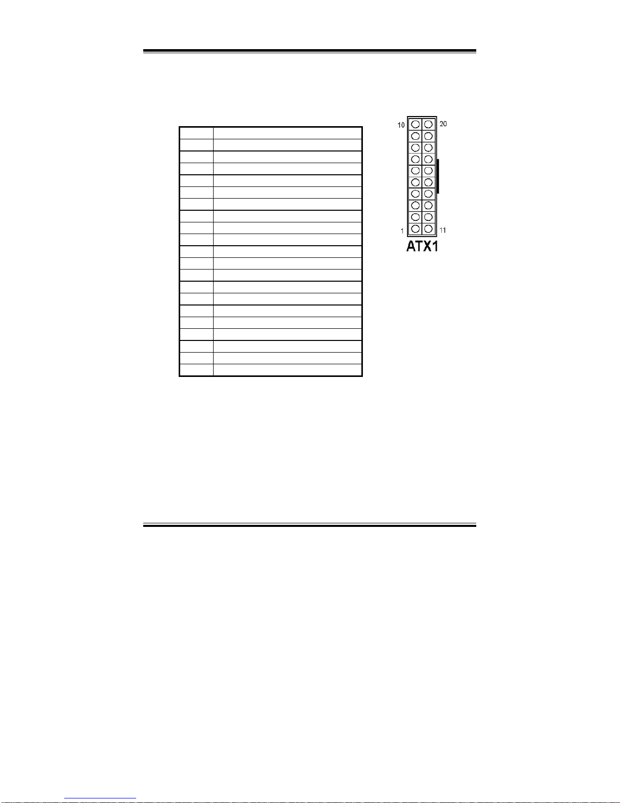
2-11. POWER CONNECTOR
ATX1: Power Connector
The pin assignments are as follows :
PIN ASSIGNMENT
1 VCC3_3
2 VCC3_3
3 GND
4 VCC
5 GND
6 VCC
7 GND
8 NC
9 5VSB
10 VCC12
11 VCC3_3
12 VCC12J
13 GND
14 PS_ON
15 GND
16 GND
17 GND
18 VCC5J
19 VCC
20 VCC
Page 36
Chapter 2 Hardware Configuration
Page: 2-18
PPC-740X USER
’S MANUAL
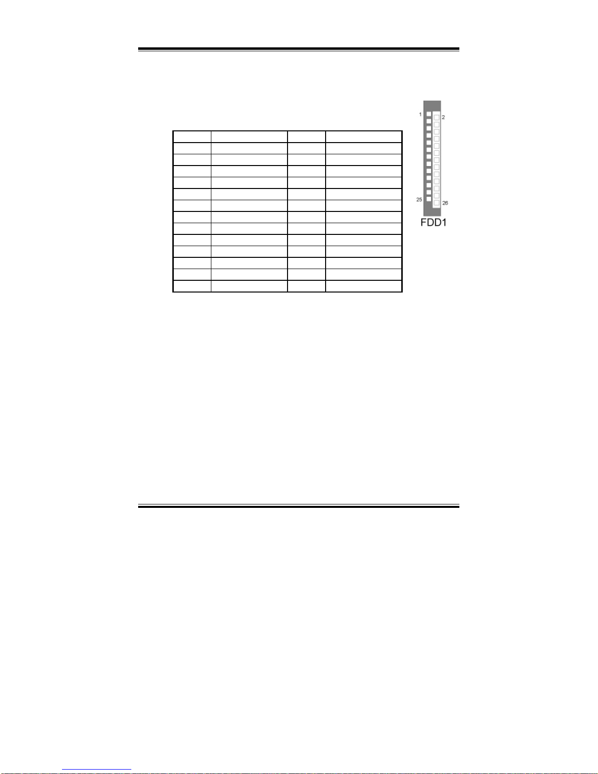
2-12. FLOPPY DISK DRIVE CONNECTOR
FDD1 : Floppy Disk Drive Connector
The pin assignments are as follows:
PIN ASSIGNMENT PIN ASSIGNMENT
1 VCC 2 INDEXJ
3 VCC 4 DSAJ
5 VCC 6 DSKCHGJ
7 NC 8 NC
9 NC 10 MOAJ
11 NC 12 DIRJ
13 RWCJ 14 STEPJ
15 NC 16 WDJ
17 GND 18 WEJ
19 GND 20 TRAK0J
21 GND 22 WPJ
23 GND 24 RDATAJ
25 GND 26 HEADJ
Page 37
Chapter 2 Hardware Configuration
PPC-740X USER’S MANUAL
Page: 2-19
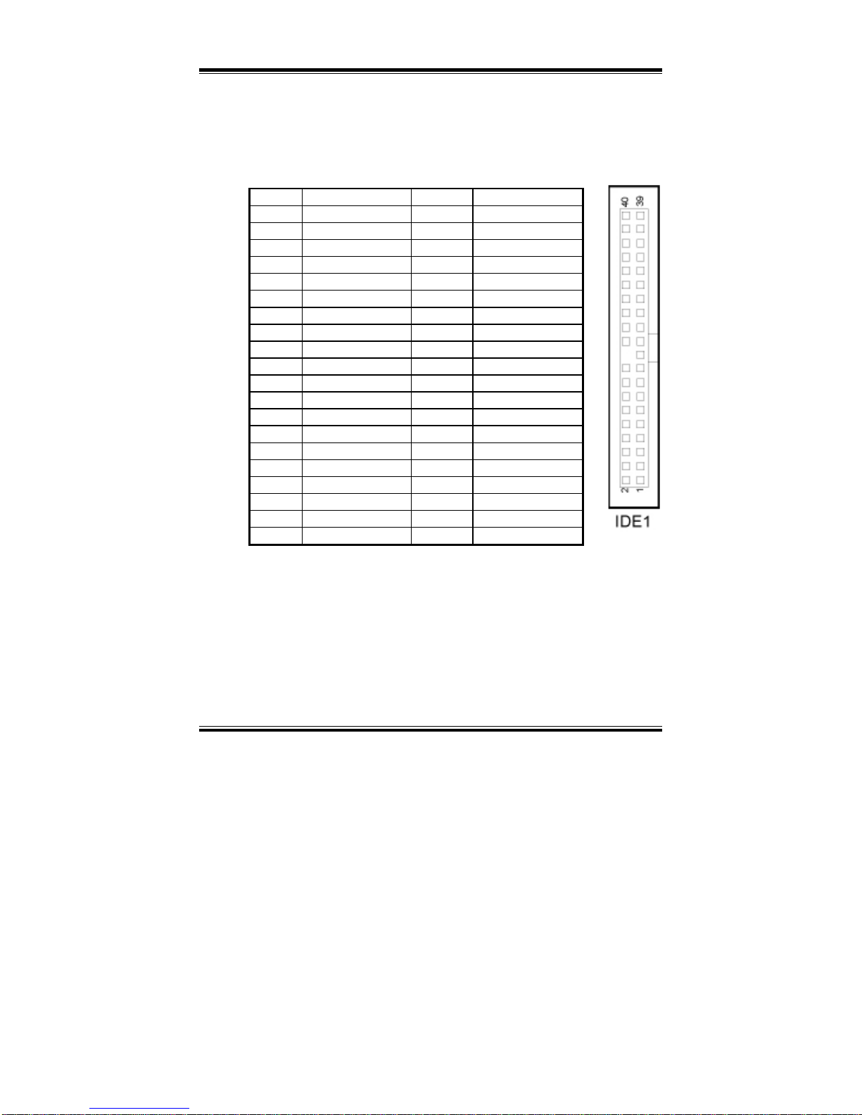
2-13. HARD DISK DRIVE CONNECTOR
IDE1 : Hard Disk Drive Connector
The pin assignments are as follows:
PIN ASSIGNMENT PIN ASSIGNMENT
1 IDERSTJ 2 GND
3 PDD7 4 PDD8
5 PDD6 6 PDD9
7 PDD5 8 PDD10
9 PDD4 10 PDD11
11 PDD3 12 PDD12
13 PDD2 14 PDD13
15 PDD1 16 PDD14
17 PDD0 18 PDD15
19 GND 20 NC
21 SDREQ 22 GND
23 SDIOWJ 24 GND
25 SDIORJ 26 GND
27 SIORDY 28 PULL LOW
29 PDDACKJ 30 GND
31 IRQ14S 32 NC
33 PDA1 34 P66DET
35 PDA0 36 PDA2
37 PDCSJ1 38 PDCSJ3
39 IDEACTPJ 40 GND
Page 38
Chapter 2 Hardware Configuration
Page: 2-20
PPC-740X USER
’S MANUAL
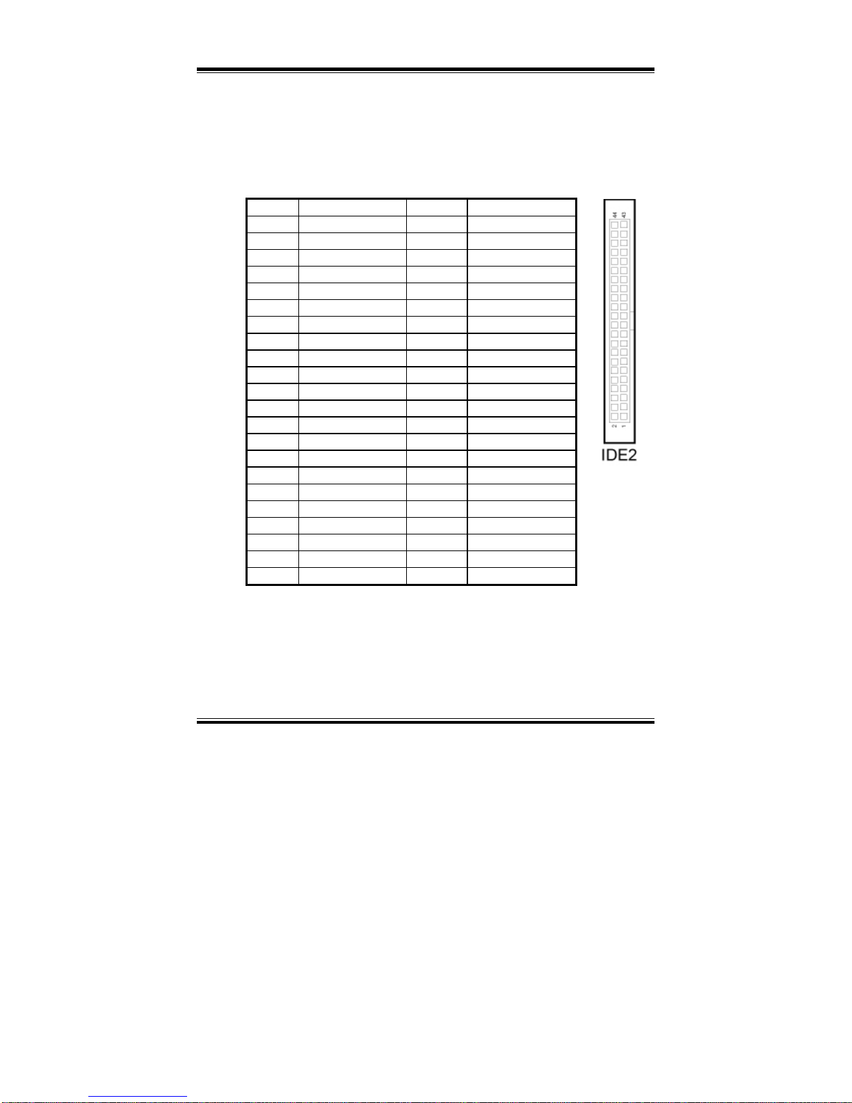
IDE2 : Hard Disk Drive Connector
The pin assignments are as follows:
PIN ASSIGNMENT PIN ASSIGNMENT
1 IDERSTJ 2 GND
3 SDD7 4 SDD8
5 SDD6 6 SDD9
7 SDD5 8 SDD10
9 SDD4 10 SDD11
11 SDD3 12 SDD12
13 SDD2 14 SDD13
15 SDD1 16 SDD14
17 SDD0 18 SDD15
19 GND 20 NC
21 SDREQJ 22 GND
23 SIOWJ 24 GND
25 SIORJ 26 GND
27 SDIORJ 28 PULL LOW
29 SDDACKJ 30 GND
31 IRQ15S 32 NC
33 SDA1 34 S66 DET
35 SDA0 36 SDA2
37 SDCSJ1 38 SDCSJ3
39 IDEACTSJ 40 GND
41 VCC 42 VCC
43 GND 44 NC
Page 39
Chapter 2 Hardware Configuration
PPC-740X USER’S MANUAL
Page: 2-21
2-14. PRINTER CONNECTOR
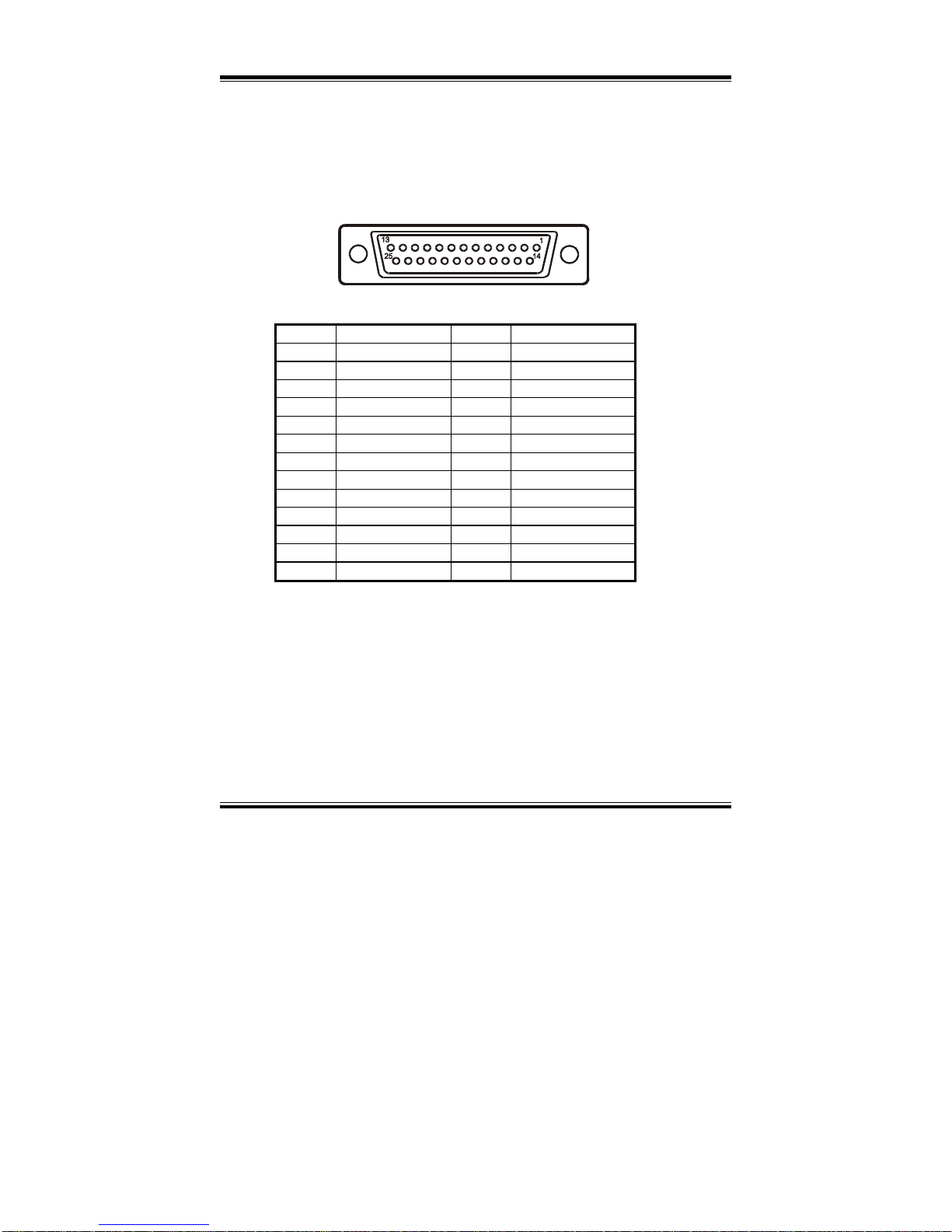
LPT1 : Printer Connector
As to link the Printer to the card, you need a cable to connect both DB25
connector and parallel port.
The pin assignments are as follows :
LPT1
PIN ASSIGNMENT PIN ASSIGNMENT
1 STBJR 14 AFDJ
2 PD0R 15 ERRJ
3 PD1R 16 PAR_INITJ
4 PD2R 17 SLINJ
5 PD3R 18 GND
6 PD4R 19 GND
7 PD5R 20 GND
8 PD6R 21 GND
9 PD7R 22 GND
10 ACKJ 23 GND
11 BUSY 24 GND
12 PE 25 GND
13 SLCT
Page 40
Chapter 2 Hardware Configuration
Page: 2-22
PPC-740X USER
’S MANUAL
2-15. LAN CONNECTOR
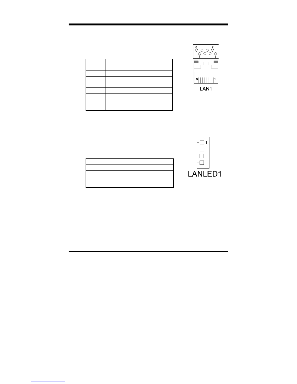
LAN1: LAN Connector.
The pin assignment is as follows :
PIN ASSIGNMENT
1 TXD0P
2 TXD0N
3 TXD1P
4 TXD2P
5 TXD2N
6 TXD1N
7 TXD3P
8 TXD3N
2-16. LAN LED CONNECTOR
LANLED1 : LAN LED Connector
The pin assignment is as follows :
PIN ASSIGNMENT
1 SPEED100J
2 SPEED1000J
3 LILEDJ
4 ACTLEDJ
Page 41
Chapter 2 Hardware Configuration
PPC-740X USER’S MANUAL
Page: 2-23
2-17. KEYBOARD CONNECTOR
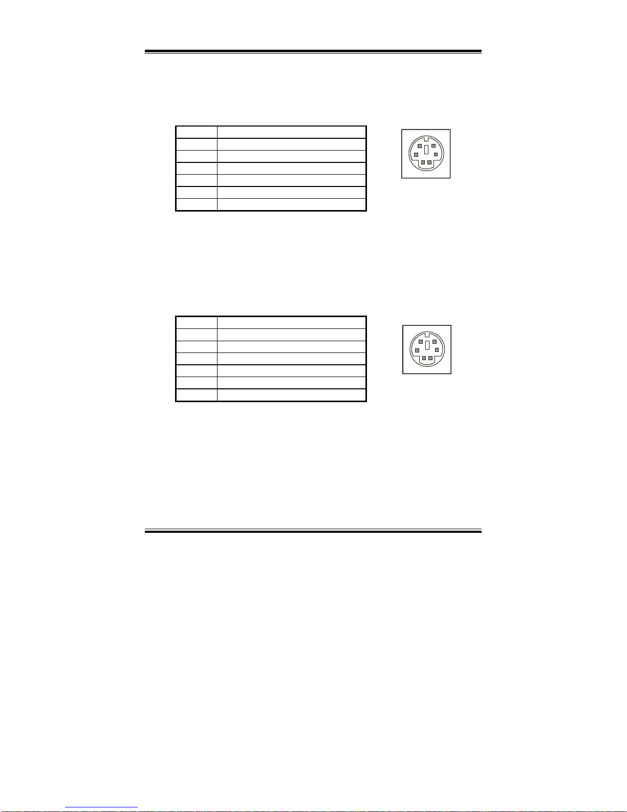
KB1 : PC/AT Keyboard Connector
The pin assignments are as follows :
PIN ASSIGNMENT
1 KB DATA
2 NC
3 GND
4 GND
5 VCC
6 KB CLK
2-18. PS/2 MOUSE CONNECTOR
MS1 : PS/2 Mouse Connector
The pin assignments are as follows :
PIN ASSIGNMENT
1 MS DATA
2 NC
3 GND
4 GND
5 NC
6 MS CLK
1
2
3
4
5
6
KB1
12
3
4
56
MS1
Page 42
Chapter 2 Hardware Configuration
Page: 2-24
PPC-740X USER
’S MANUAL
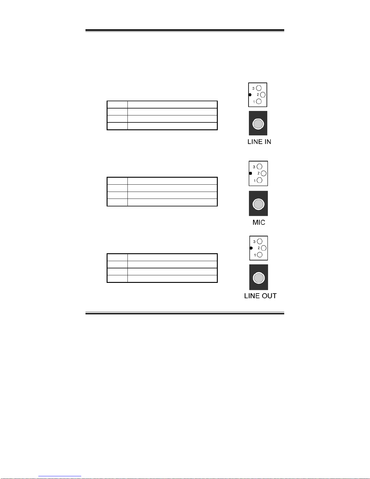
2-19. SOUND CONNECTOR
The sound connector is composed of the Microphone (MIC1), Line-Out
(LINE_OUT), Line-In (LINE_IN) and CDIN connector.
LINE IN : Line-In Connector
The pin assignment is as follows :
PIN ASSIGNMENT
1 GND
2 LINE_L
3 LINE_R
MIC1 : Microphone Connector
The pin assignment is as follows :
PIN ASSIGNMENT
1 GND
2 MIC-IN
3 MIC VDD
LINE OUT : Line-Out Connector
The pin assignment is as follows :
PIN ASSIGNMENT
1 GND
2 Line-Out-L
3 Line-Out-R
Page 43
Chapter 2 Hardware Configuration
PPC-740X USER’S MANUAL
Page: 2-25
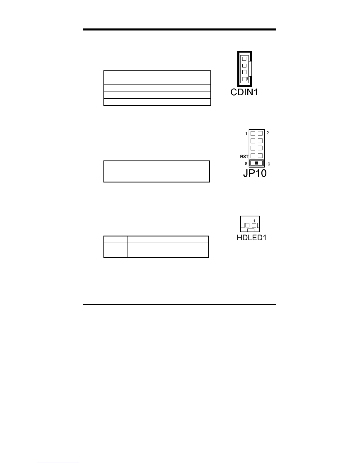
CDIN1 : CDIN Connector
The pin assignment is as follows :
PIN ASSIGNMENT
1 CD-L
2 CDGND
3 CDGND
4 CD-R
2-20. RESET CONNECTOR
JP10 (9-10) : Reset Connector.
The pin assignment is as follows :
PIN ASSIGNMENT
9 GND
10 RSTSW
2-21. HDD LED CONNECTOR
HDLED1 : HDD LED Connector
The pin assignment is as follows :
PIN ASSIGNMENT
1 HD_LED+
2 HD_LED-
Page 44
Chapter 2 Hardware Configuration
Page: 2-26
PPC-740X USER
’S MANUAL
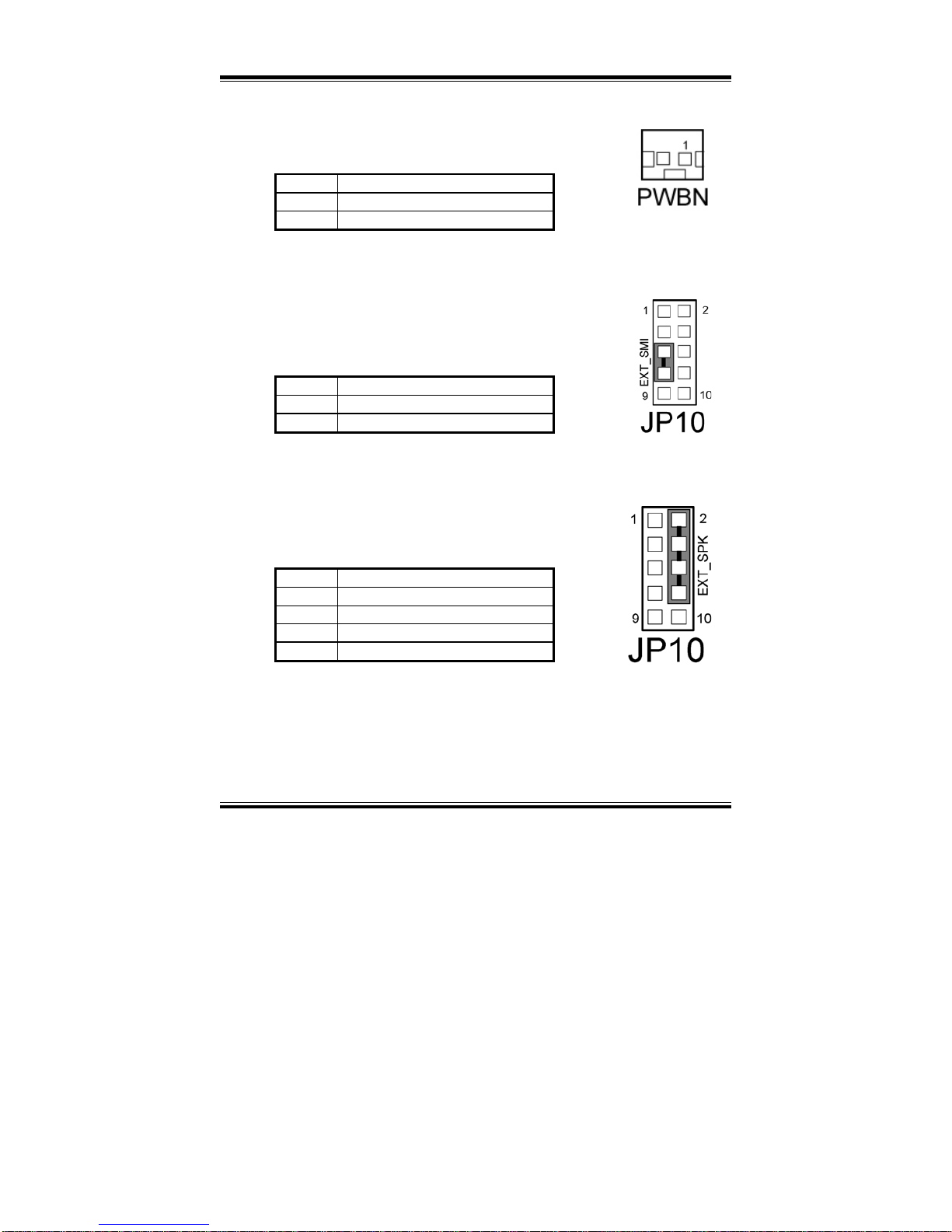
2-22. POWER BUTTON
PWBN : Power Button
The pin assignments are as follows:
PIN ASSIGNMENT
1 PW_BN1
2 PANSWIN
2-23. EXTERNAL SMI CONNECTOR
JP10 (5,7) : External SMI Connector.
The pin assignments are as follows :
PIN ASSIGNMENT
5 P_ESMI
7 GND
2-24. EXTERNAL SPEAKER CONNECTOR
JP10 (2, 4, 6, 8) : External Speaker Connector.
The pin assignments are as follows :
PIN ASSIGNMENT
2 VCC
4 P_SPK
6 P_SPK
8 P_SPK
Page 45
Chapter 2 Hardware Configuration
PPC-740X USER’S MANUAL
Page: 2-27
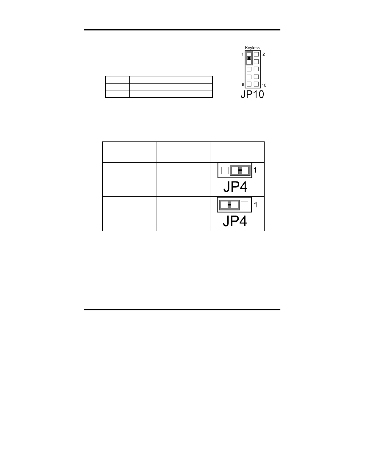
2-25. KEYLOCK CONNECTOR
JP10 (1, 3) : Keylock Connector.
The pin assignments are as follows :
PIN ASSIGNMENT
1 KEYLOCKJ
3 GND
2-26. CMOS FUNCTION SELECTION
JP4: CMOS Function Selection
The selections are as follows:
FUNCTION
JUMPER SETTING
(pin closed)
JUMPER
ILLUSTRATION
NORMAL
1-2
CLEAR CMOS
2-3
*** Manufacturing Default – Normal.
To clear CMOS data, user must power-off the computer and set the jumper to
“Clear CMOS” as illustrated above. After five to six seconds, set the jumper back
to “Normal” and power-on the computer.
Page 46
Chapter 2 Hardware Configuration
Page: 2-28
PPC-740X USER
’S MANUAL
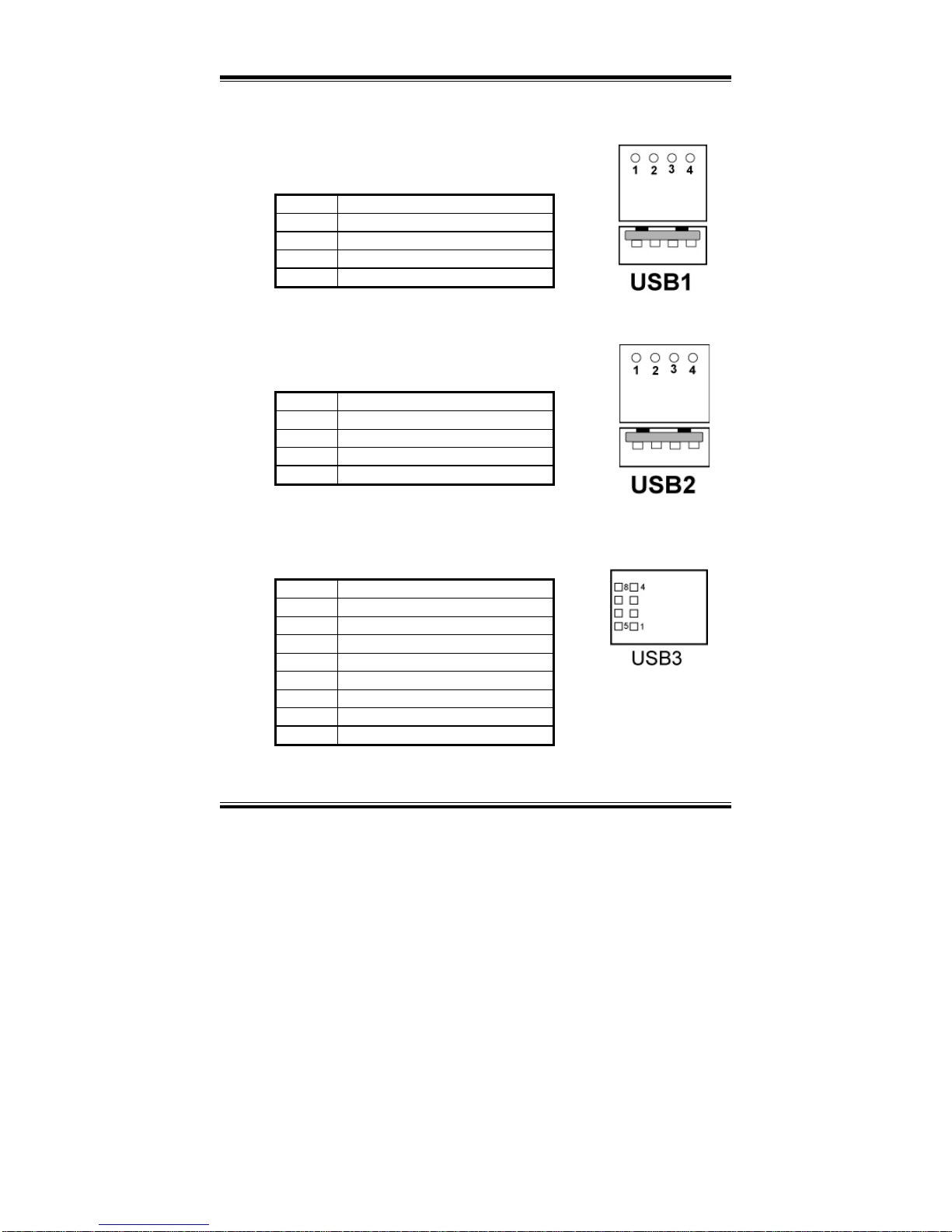
2-27. UNIVERSAL SERIAL BUS CONNECTOR
USB1: Universal Serial Bus Connector.
The pin assignments are as follows :
PIN ASSIGNMENT
1 USBV0 (Max. 500mA)
2 USBP0N
3 USBP0P
4 GND
USB2: Universal Serial Bus Connector.
The pin assignments are as follows :
PIN ASSIGNMENT
1 USBV1 (Max. 500mA)
2 USBP1N
3 USBP1P
4 GND
USB3 : Universal Serial Bus Connector.
The pin assignments are as follows :
PIN ASSIGNMENT
1 NC
2 NC
3 NC
4 NC
5 USBV2 (Max. 500mA)
6 USBP2N
7 USBP2P
8 GND
Page 47
Chapter 2 Hardware Configuration
PPC-740X USER’S MANUAL
Page: 2-29
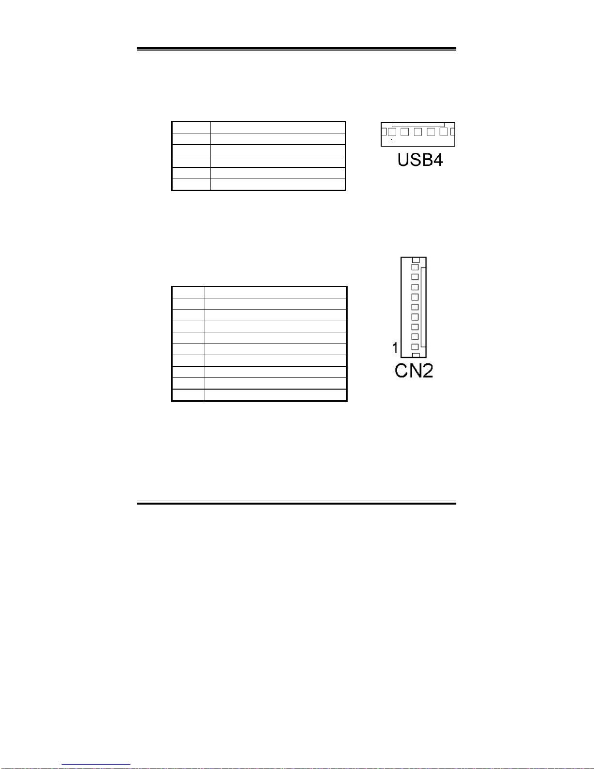
USB4 : Universal Serial Bus Connector. The USB connector is reserved for
touch panel.
The pin assignments are as follows :
PIN ASSIGNMENT
1 USBV3
2 USBP3N
3 USBP3P
4 GND
5 GND
2-28. INVERTER CONNECTOR
CN2 : Inverter Connector
The pin assignments are as follows:
PIN ASSIGNMENT
1 V12SAFE
2 GND
3 BRCRT
4 NC
5 V5SAFE
6 GND
7 LINE-OUT-R
8 GND
9 LINE-OUT-L
Page 48
Chapter 2 Hardware Configuration
Page: 2-30
PPC-740X USER
’S MANUAL
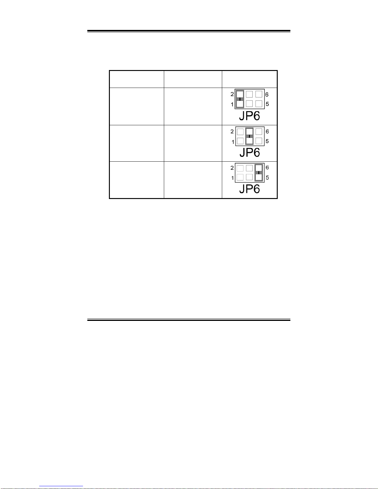
2-29. RESET / NMI /CLEAR WATCHDOG SELECTION
JP6 : Reset/NMI/Clear Watchdog Selection
The selections are as follows:
FUNCTION JUMPER SETTING
JUMPER
ILLUSTRATION
Reset 1-2
NMI 3-4
Watchdog 5-6
*** Manufacturing Default --- is set as Reset.
User may select to use the Reset or NMI watchdog. NMI, also known as Non-Maskable
Interrupt, is used for serious conditions that demand the processor’s immediate attention,
it cannot be ignored by the system unless it is shut off specifically. To clear NMI
command, user should short the “Clear Watchdog” pin via push button.
Page 49
Chapter 2 Hardware Configuration
PPC-740X USER’S MANUAL
Page: 2-31
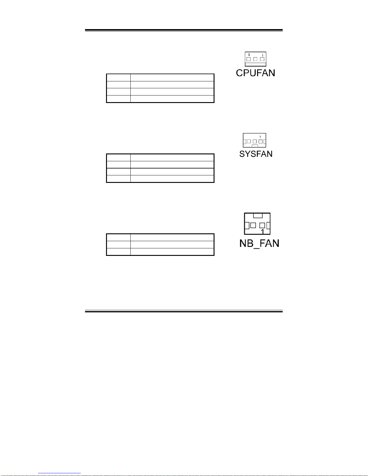
2-30. CPU FAN CONNECTOR
CPUFAN : CPU Fan Connector
The pin assignments are as follows :
PIN ASSIGNMENT
1 GND
2 VCC12 (Max. 1A)
3 FANIO1
2-31. SYSTEM FAN CONNECTOR
SYSFAN : System Fan Connector
The pin assignments are as follows :
PIN ASSIGNMENT
1 VCC12 (Max. 1A)
2 GND
3 VCC12 (Max. 1A)
2-32. NORTH CHIP FAN CONNECTOR
NB_FAN : North Chip Fan Connector
The pin assignments are as follows :
PIN ASSIGNMENT
1 VCC (Max. 1A)
2 GND
Page 50
Chapter 2 Hardware Configuration
Page: 2-32
PPC-740X USER
’S MANUAL
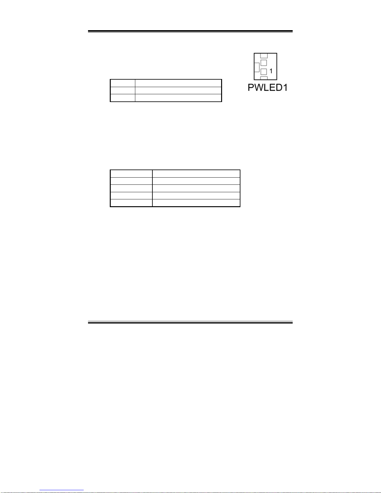
2-33. POWER LED CONNECTOR
PWLED1: Power LED Connector.
The pin assignments are as follows :
PIN ASSIGNMENT
1 PW_LED+
2 PW_LED-
2-34. MEMORY INSTALLATION
This system is enhanced with 1 DDR DRAM banks, which support up to
1G.
DRAM BANK CONFIGURATION
DIMM 1 TOTAL MEMORY
128M 128MB
256M 256MB
512M 512MB
1G 1G
Page 51
Chapter 2 Hardware Configuration
PPC-740X USER’S MANUAL
Page: 2-33
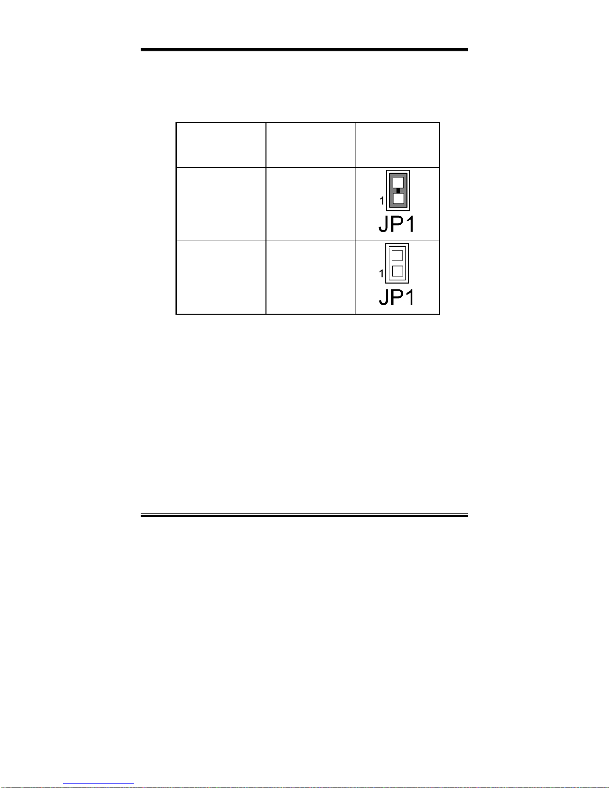
2-35. P4/P4-M CPU SELECTION
JP1 : P4/P4-M CPU Selection.
The selections are as follows:
FUNCTION
JUMPER SETTING
JUMPER
ILLUSTRATION
P4-M 1-2
P4
(Default)
Open
Please be aware that when using Pentium 4-M CPU, JP1 jumper must
set as closed, otherwise the P4-M CPU will be damaged, vice versa.
Page 52
Chapter 2 Hardware Configuration
Page: 2-34
PPC-740X USER
’S MANUAL
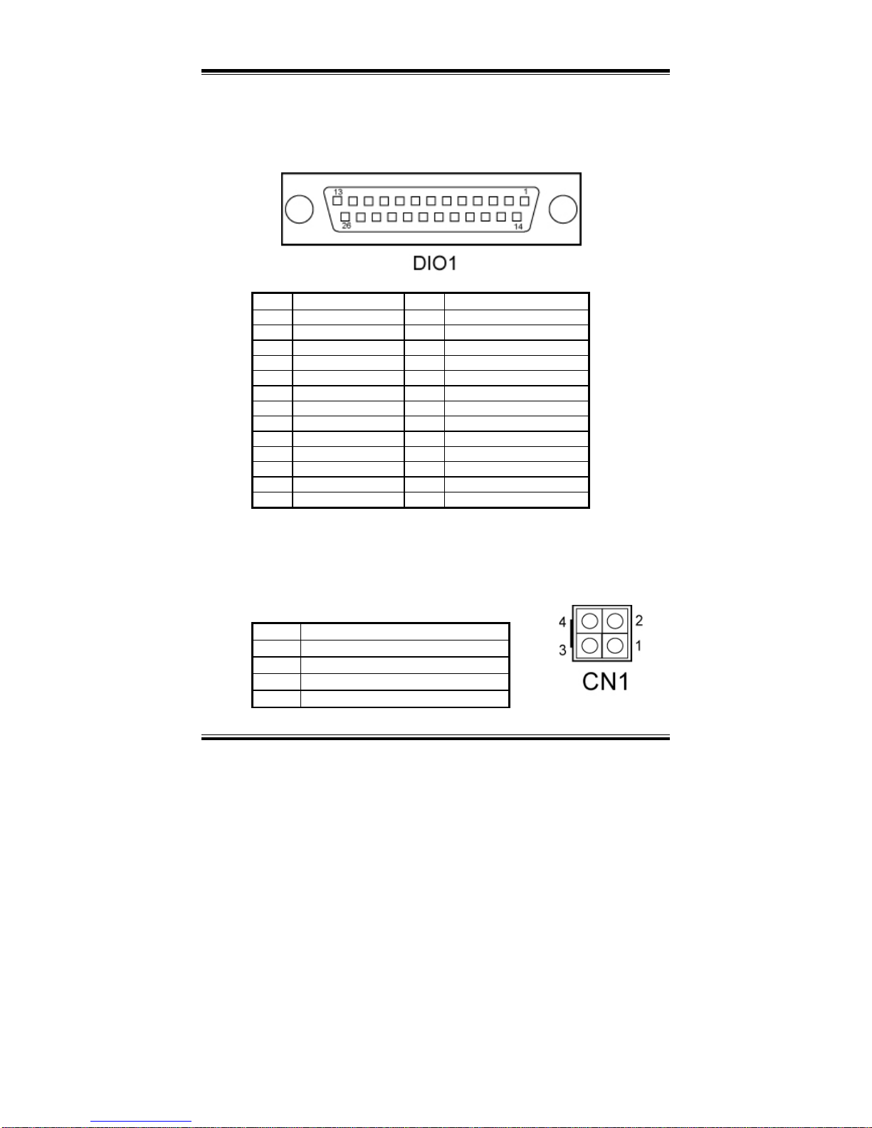
2-36. DIGITAL INPUT/OUTPUT CONNECTOR
DIO1 : Digital I/O Connector
The pin assignments are as follows :
PIN ASSIGNMENT
PIN
ASSIGNMENT
1 DIN0 14 DOUT5
2 DIN1 15 DOUT6
3 DIN2 16 DOUT7
4 DIN3 17 GND
5 DIN4 18 GND
6 DIN5 19 GND
7 DIN6 20 GND
8 DIN7 21 GND
9 DOUT0 22 GND
10 DOUT1 23 GND
11 DOUT2 24 GND
12 DOUT3 25 GND
13 DOUT4 26 GND
2-37. ATX +12V POWER CONNECTOR
CN1 : ATX +12V Power Connector
The pin assignments are as follows:
PIN ASSIGNMENT
1 GND
2 GND
3 VCC12V_CPU
4 VCC12V_CPU
Page 53
Chapter 2 Hardware Configuration
PPC-740X USER’S MANUAL
Page: 2-35
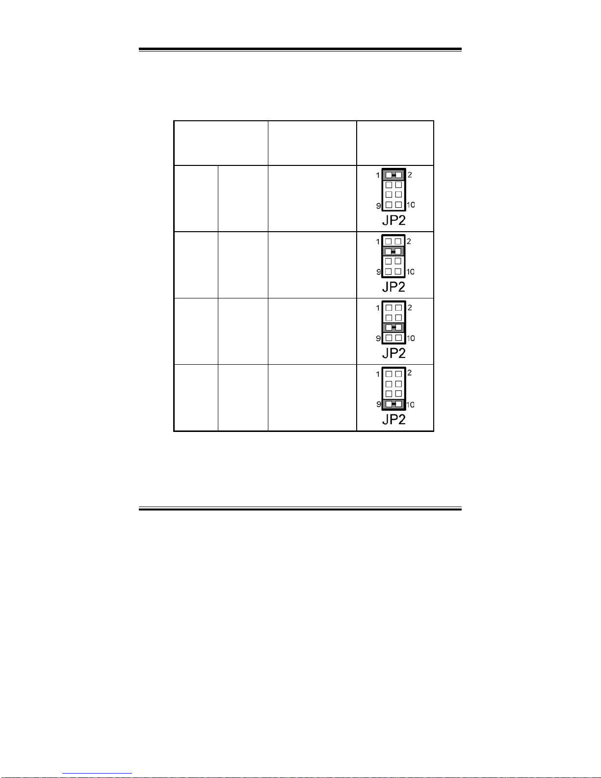
2-38. LVDS PANEL RESOLUTION SELECTION
JP2 : LVDS Panel Resolution Selection.
The selections are as follows:
FUNCTION
JUMPER SETTING
(pin closed)
JUMPER
ILLUSTRATION
Hardware
Setting
800 x 600 1-2
Hardware
Setting
1024 x 768 3-4
Hardware
Setting
1280 x 1024
5-6
Software
Setting
(default)
1024 x 768 7-8
Page 54

Page: 3-1
SOFTWARE
UTILITIES
This chapter comprises the detailed information of VGA driver, LAN
driver, and sound driver, VIA Chipset Software Installation Utility,
touch screen driver, USB 2.0 driver and Flash BIOS update. It also
describes how to install the watchdog timer configuration.
Section includes:
z Introduction
z VGA Driver Utility
z Flash BIOS Update
z LAN Driver Utility
z Sound Driver Utility
z Intel® Chipset Software Installation Utility
z USB2.0 Chipset Software Installation Utility
z Touch screen Driver Utility (Optional)
z Watchdog Timer Configuration
CHAPTER
3
Page 55

Chapter 3 Software Configuration
Page:3-2
PPC-740X USER
c
S MANUAL
3-1. INTRODUCTION
Enclosed with our PPC-740X package is our driver utility, which may comes
in a form of a CD ROM disc or floppy diskettes. For CD ROM disc user,
you will only need some of the files contained in the CD ROM disc, please
kindly refer to the following chart:
Filename
(Assume that CD ROM drive is D:)
Purpose
D:\VGA Intel 845GV
For VGA driver installation
D:\FLASH For BIOS update utility
D:\LAN Intel 82541GI
For LAN Driver installation
D:\SOUND Realtel ALC202A AC97
For Sound driver installation
D:\UTILITY Intel® Chipset Software
Installation Utility
For Win 98SE,ME, 2000, XP
D:\USB 2.0 USB 2.0 Software Installation
Utility
For Win 98SE, 2000, ME, XP
D:\Touch Screen Drv\ For Fujitsu Touch screen driver
User should remember to install the Utility right after the OS fully installed.
Page 56
Chapter 3 Software Configuration
PPC-740X USERcS MANUAL
Page:3-3
3-2. VGA DRIVER UTILITY
The VGA interface embedded with our PPC-740X can support a wide
range of display. You can display CRT, LVDS and PanelLink™
simultaneously with the same mode.
1. Win 9X program
2. Win NT4.0 program
3. Win 2000 program
4. Win XP program
3-2-1. Installation of VGA Driver:
To install the VGA Driver, simply follow the following steps:
1. Place insert the Utility Disk into Floppy Disk Drive A/B or CD
ROM drive.
2. Under Windows 9X/NT4.0/2000/XP system, go to the directory
where VGA driver is located.
3. Click Setup file for VGA driver installation.
4. Follow the instructions on the screen to complete the installation.
5. Once installation is completed, shut down the system and restart in
order for the changes to take effect.
Page 57

Chapter 3 Software Configuration
Page:3-4
PPC-740X USER
c
S MANUAL
3-3. FLASH BIOS UPDATE
3-3-1. System BIOS Update:
Users of PPC-740X can use the program “Awdflash.exe” contained in
the Utility Disk for system BIOS and VGA BIOS update.
3-3-2. To update VGA BIOS for LCD Flat Panel Display:
As PPC-740X user, you have to update the VGA BIOS for your specific
LCD flat panel you are going to use. For doing this, you need two files.
One is the “Awdflash.exe” file and the other is the VGA BIOS for ATI
Rage Mobility M6 file for LCD panel display. Both file must be
provided by the vendor or manufacturer. When you get these two files
ready, follow the following steps for updating your VGA BIOS:
1. Install “Awdflash.exe” from Utility Disk to Drive C.
2. Insert the VGA BIOS file you have obtained from the vendor.
Type the path to Awdflash.exe and execute the VGA BIOS update
with file H15bxxxx.bin
3. C:\UTIL\AWDFLASH>AWDFLASH H15bxxxx.bin
4. The screen will display as the table fount on the next page:
FLASH MEMORY WRITER v8.XX
(C) Award Software 2001 All Rights Reserved
Flash Type – SST 49LF004A /3.3V
File Name to Program:
H20bxxxx.bin
Checksum: XXXXX
Error Message: Do You Want To Save BIOS (Y/N)
If you want to save up the original BIOS, enter "Y" and press < Enter >.
If you choose "N", the following table will appear on screen.
Page 58

Chapter 3 Software Configuration
PPC-740X USERcS MANUAL
Page:3-5
FLASH MEMORY WRITER v8.XX
(C) Award Software 2001 All Rights Reserved
Flash Type – SST 49LF004A /3.3V
File Name to Program: H20bxxxx.bin
Checksum: XXXXX
Error Message : Are You Sure To Program (Y/N)
Select "Y", and the BIOS will be renewed. When you are refreshing the
BIOS, do not turn off or reset the system, or you will damage the BIOS.
After you have completed all the programming, the screen displays the
table below:
FLASH MEMORY WRITER v8.XX
(C) Award Software 2001 All Rights Reserved
Flash Type – SST 49LF004A /3.3V
File Name to Program: H20bxxxx.bin
Checksum: XXXXX
Reset System or Power off to
accomplish update process!
F1: Reset F10: Exit
Please reset or power off the system, and then the Flash BIOS is fully
implemented.
Page 59
Chapter 3 Software Configuration
Page:3-6
PPC-740X USER
c
S MANUAL
3-4. LAN DRIVER UTILITY
3-4-1. Introduction
PPC-740X is enhanced with LAN function that can support various
network adapters. Installation programs for LAN drivers are listed as
follows:
1. Win 98SE/ME program
2. Win 2000/XP program
3. Win NT4.0 program
4. Linux
5. Netware program
6. Unixware 7.x
For more details on Installation procedure, please refer to Readme.txt
file found on LAN DRIVER UTILITY.
Page 60
Chapter 3 Software Configuration
PPC-740X USERcS MANUAL
Page:3-7
3-5. SOUND DRIVER UTILITY
3-5-1. Introduction
The Realtek ALC202A sound function enhanced in this system is fully
compatible with Windows 98, Windows 98SE, Windows NT 4.0,
Windows 2000, Windows ME and Windows XP. Below, you will find
the content of the Sound driver :
1. Win 98 program
2. Win 98SE program
3. Win NT 4.0 program
4. Win 2000 program
5. Win ME program
6. Win XP program
3-5-2. Installation Procedure for Windows 9x/NT/2000/XP
1. From the task bar, click on Start, and then Run.
2. In the Run dialog box, type D:\Sound\ setup, where
“D:\Sound\pathname” refers to the full path to the source files.
3. Click on the OK button or press the ENTER key.
4. Click on the “Next” and OK prompts as they appear.
5. Reboot the system to complete the driver installation.
Page 61

Chapter 3 Software Configuration
Page:3-8
PPC-740X USER
c
S MANUAL
3-6. INTEL® C HIPSET SOFTWARE INSTALLATION UTILITY
3-6-1. Introduction
The Intel® Chipset Software Installation Utility installs to the target
system the Windows* INF files that outline to the operating system how
the chipset components will be configured. This is needed for the
proper functioning of the following features:
- Core PCI and ISAPNP Services
- AGP Support
- IDE/ATA33/ATA66/ATA100 Storage Support
- USB Support
- Identification of Intel® Chipset Components in Device Manager
3-6-2. Installation of Utility for Windows 98SE/ME/2000/XP
The Utility Pack is to be installed only for Windows 98SE, Windows
ME, Windows 2000 and XP program.
It should be installed right after the OS installation, kindly follow the
following steps:
1. Place insert the Utility Disk into Floppy Disk Drive A/B or CD
ROM drive.
2. Under Windows 98SE/ME/2000/XP system, go to the directory
where Utility Disc is located.
3. Click Setup file for utility installation.
4. Follow the instructions on the screen to complete the installation.
5. Once installation is completed, shut down the system and restart in
order for the changes to take effect.
Page 62

Chapter 3 Software Configuration
PPC-740X USERcS MANUAL
Page:3-9
3-7. USB2.0 SOFTWARE INSTALLATION UTILITY
3-7-1. Installation of Utility for Windows 98SE/ 2000/XP
Intel USB 2.0 Enhanced Host Controller driver can only be used on
Windows 98SE, Windows 2000 and Windows XP on Intel Desktop
boards. It should be installed right after the OS installation, kindly
follow the following steps:
1. Place insert the Utility Disk into Floppy Disk Drive A/B or CD
ROM drive.
2. Under Windows 98SE, 2000, and XP system, go to the directory
where Utility Disc is located.
3. Start the “System” wizard in control panel. (Click
Start/Settings/Control Panel).
4. Select “Hardware” and click “Device Manager ” button.
5. Double Click “USB Root Hub”.
6. Select “Driver”.
7. Click “Install” to install the driver.
8. Follow the instructions on the screen to complete the installation.
9. Click “Finish” after the driver installation is complete.
3-8. TOUCH SCREEN DRIVER UTILITY (OPTIONAL)
To install, kindly refer to the readme.txt file found each separate file of
the Driver Disc.
✆ If the installation time is over 1 hour, please go to BIOS setting, under
“Integrated Peripherals” item to set the “USB2.0 Controller” to disable.
Page 63

Chapter 3 Software Configuration
Page:3-10
PPC-740X USER
c
S MANUAL
3-9. WATCHDOG TIMER CONFIGURATION
This board has watchdog timer function for monitoring whether the system
is still work or not after a period of time. The user can select watchdog
timer to system reset or NMI (Non Maskable interrupt) depending on the
jumper set in chapter 2. This is defined at I/O port 443H. When you want to
enable the watchdog timer, please write I/O port 443H, and then the system
will either reset itself or perform the NMI function. Likewise, when you
want to disable the function, write I/O port 441H, the system will run the
command to stop the Watchdog function.
In PPC-740X watchdog function, you must write your program so when it
writes I/O port address 443 for enable watchdog and write I/O port address
441 for disable watchdog. The timer's intervals have a tolerance of 25%
(but for level 1 and 2, the tolerance is 4%), so you should program an
instruction that will refresh the timer about every second.
The following program shows you how to program the watch timer in your
program.
Watchdog enable program:
MOV AX, 000FH (choose the values you need; start from 0)
MOV DX, 443H
OUT DX, AX
Watchdog disable program:
MOV AX, 000FH (this value can be ignored)
MOV DX, 441H
OUT DX, AX
The Watchdog Timer control table is as follows:
Level Value Time/sec Level Value Time/sec
1 F 0 9 7 64
2 E 8 10 6 72
3 D 16 11 5 80
4 C 24 12 4 88
5 B 32 13 3 96
6 A 40 14 2 104
7 9 48 15 1 112
8 8 56 16 0 120
Page 64

Page: 4-1
AWARD
BIOS SETUP
This chapter shows how to set up the Award BIOS.
Section includes:
Introduction
Entering Setup
The Standard CMOS Features
The Advanced BIOS Features
The Advanced Chipset Features
Integrated Peripherals
Power Management Setup
PNP/PCI Configurations
PC Health Status
Frequency/Voltage Control
Load Fail-Safe Defaults
Load Optimized Defaults
Password Setting
Save and Exit Setup
Exit Without Saving
CHAPTER
4
Page 65
Chapter 4 Award BIOS Setup
Page: 4-2
PPC-740X USER
′
S MANUAL
4-1. INTRODUCTION
This chapter will show you the function of the BIOS in managing the
features of your system. The PPC-740X Panel PC is equipped with the BIOS
for system chipset from Award Software Inc. This page briefly explains the
function of the BIOS in managing the special features of your system. The
following pages describe how to use the BIOS for system chipset Setup
menu.
Your application programs (such as word processing, spreadsheets, and
games) rely on an operating system such as DOS or OS/2 to manage such
things as keyboard, monitor, disk drives, and memory.
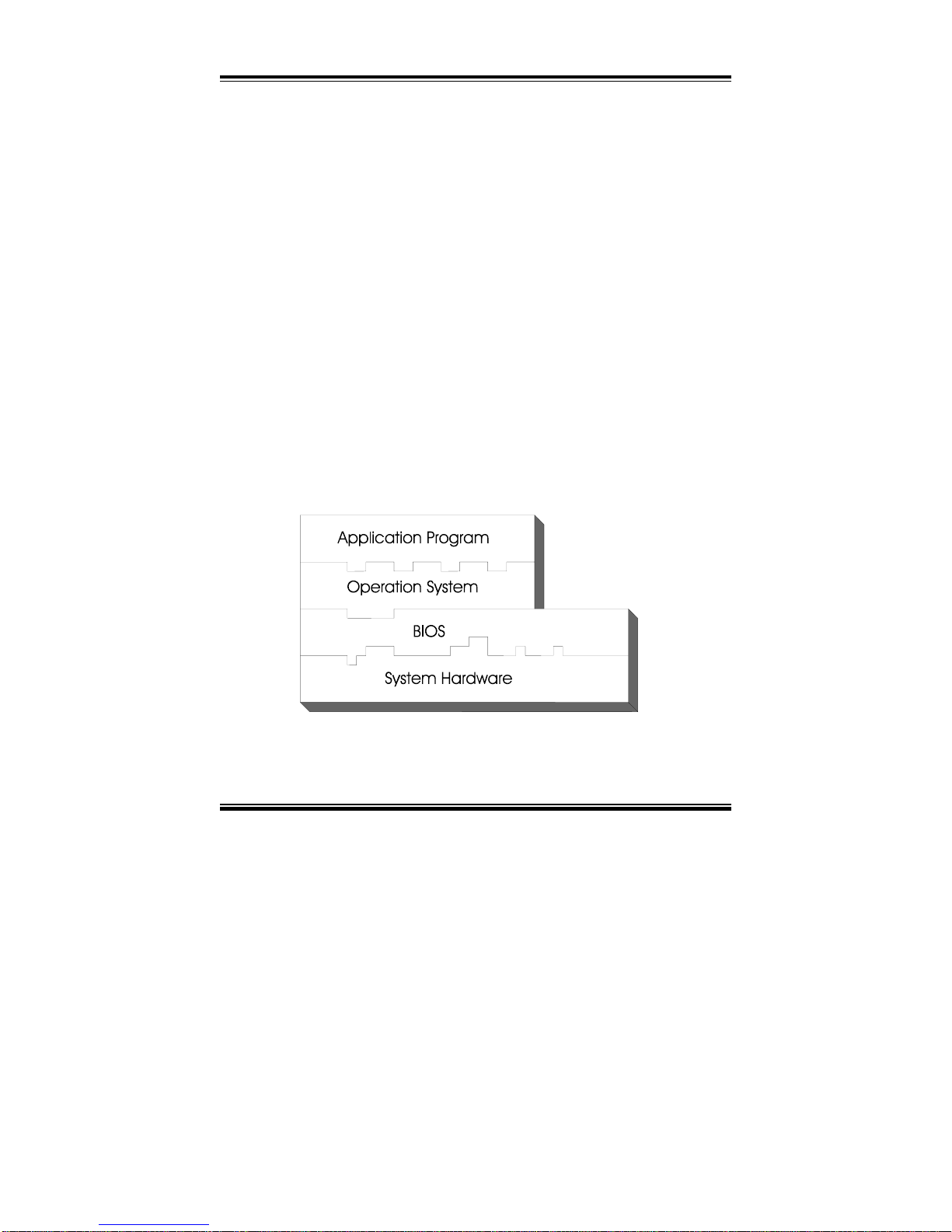
The operating system relies on the BIOS (Basic Input and Output system), a
program stored on a ROM (Read-only Memory) chip, to initialize and
configure your computer's hardware. As the interface between the hardware
and the operating system, the BIOS enables you to make basic changes to
your system's hardware without having to write a new operating system.
The following diagram illustrates the interlocking relationships between the
system hardware, BIOS, operating system, and application program:
Page 66

Chapter 4 Award BIOS Setup
PPC-740X USER′S MANUAL
Page: 4-3
4-2. ENTERING SETUP
When the system is powered on, the BIOS will enter the Power-On Self
Test (POST) routines and the following message will appear on the lower
screen:
PRESS <DEL> TO ENTER SETUP, ESC TO SKIP MEMORY TEST
As long as this message is present on the screen you may press the <Del>
key (the one that shares the decimal point at the bottom of the number
keypad) to access the Setup program. In a moment, the main menu of the
Award SETUP program will appear on the screen:
Phoenix - AwardBIOS CMOS Setup Utility
►Standard CMOS Features
►Advanced BIOS Features
►Advanced Chipset Features
►Integrated Peripherals
►Power Management Setup
►PnP/PCI Configurations
►PC Health Status
►Frequency/Voltage Control
Load Fail-Safe Defaults
Load Optimized Defaults
Set Supervisor Password
Set User Password
Save & Exit Setup
Exit Without Saving
Esc : Quit ↑↓→← : Select Item
F10 : Save & Exit Setup
Time, Date, Hard Disk Type .…
Setup program initial screen
You may use the cursor the up/down keys to highlight the individual menu
items. As you highlight each item, a brief description of the highlighted
selection will appear at the bottom of the screen.
Page 67

Chapter 4 Award BIOS Setup
Page: 4-4
PPC-740X USER
′
S MANUAL
4-3. THE STANDARD CMOS FEATURES
Highlight theňSTANDARD CMOS FEATURESʼnand press the <ENTER>
key and the screen will display the following table:
Phoenix - AwardBIOS CMOS Setup Utility
Standard CMOS Features
Date (mm:dd:yy)
Time (hh:mm:ss)
Thu, Oct 28 2004
10 : 21 : 13
Item Help
▶ IDE Primary Master
▶ IDE Primary Slave
▶ IDE Secondary Master
▶ IDE Secondary Slave
Drive A
Drive B
Video
Halt On
Base Memory
Extended Memory
Total Memory
[None]
[None]
[None]
[None]
[1.44M, 3.5 in.]
[None]
[EGA/VGA]
[All, But Keyboard]
640K
252928K
253952K
Menu Level ►
Change the day, month,
year and century
↑↓→←:Move Enter: Select +/-/PU/PD:Value F10:Save ESC:Exit F1:General Help
F5: Previous Values F6:Fail-Safe Defaults F7:Optimized Defaults
CMOS Setup screen
In the above Setup Menu, use the arrow keys to highlight the item and then use
the <PgUp> or <PgDn> keys to select the value you want in each item.
Date:
< Month >, < Date > and <Year >. Ranges for each value are in the CMOS
Setup Screen, and the week-day will skip automatically.
Time:
< Hour >, < Minute >, and < Second >. Use 24 hour clock format, i.e., for PM
numbers, add 12 to the hour. For example: 4: 30 P.M. You should enter the
time as 16:30:00.
Page 68

Chapter 4 Award BIOS Setup
PPC-740X USER′S MANUAL
Page: 4-5
IDE Primary Master / Slave:
IDE Secondary Master / Slave:
The BIOS can automatically detect the specifications and optimal operating
mode of almost all IDE hard drives. When you select type AUTO for a hard
drive, the BIOS detect its specifications during POST, every time system
boots.
If you do not want to select drive type AUTO, other methods of selecting
drive type are available:
1. Match the specifications of your installed IDE hard drive(s) with the
preprogrammed values for hard drive types 1 through 45.
2. Select USER and enter values into each drive parameter field.
3. Use the IDE HDD AUTO DETECTION function in Setup.
Here is a brief explanation of drive specifications:
• Type: The BIOS contains a table of pre-defined drive types. Each
defined drive type has a specified number of cylinders, number of heads,
write precompensation factor, landing zone, and number of sectors.
Drives whose specifications do not accommodate any predefine type are
classified as type USER.
• Size: Disk drive capacity (approximate). Note that this size is usually
greater than the size of a formatted disk given by a disk-checking
program.
• Cyls: number of cylinders.
• Head: number of heads.
• Precomp: write precompensation cylinders.
• Landz: landing zone.
• Sector: number of sectors.
• Mode: Auto, Normal, Large or LBA.
• Auto: The BIOS automatically determines the optimal mode.
Normal: Maximum number of cylinders, heads, sectors supported
are 1024, 16 and 63.
Large: For drives that do not support LBA and have more than
1024 cylinders.
Page 69

Chapter 4 Award BIOS Setup
Page: 4-6
PPC-740X USER
′
S MANUAL
LBA (Logical Block Addressing): During drive accesses, the IDE
controller transforms the data address described by sector, head
and cylinder number into a physical block address, significantly
improving data transfer rates. For drives greater than 1024
cylinders.
DRIVE A AND DRIVE B:
Select the type of floppy disk drive installed in your system. The available
options are 360KB 5.25in, 1.2KB 5.25in, 720KB 3.5in, 1.44MB 3.5in,
2.88MB 3.5in and None.
VIDEO:
This category selects the type of video adapter used for the primary system
monitor. Although secondary monitors are supported, you do not have to
select the type in Setup. Available Options are as follows:
EGA/VGA Enhanced Graphics Adapter/Video Graphics Array.
For EGA, VGA, SEGA, SVGA or PGA monitor
adapters.
CGA 40 Color Graphics Adapter, power up in 40 column mode.
CGA 80 Color Graphics Adapter, power up in 80 column mode.
MONO Monochrome adapter, includes high resolution
monochrome adapters.
HALT ON:
This category allows user to choose whether the computer will stop if an error
is detected during power up. Available options are “All errors”, “No errors”,
“All, But keyboard”, “All, But Diskette”, and “All But Disk/Key”.
BASE MEMORY:
Displays the amount of conventional memory detected during boot up.
EXTENDED MEMORY:
Displays the amount of extended memory detected during boot up.
TOTAL MEMORY:
Displays the total memory available in the system.
Page 70

Chapter 4 Award BIOS Setup
PPC-740X USER′S MANUAL
Page: 4-7
HARD DISK ATTRIBUTES:
Type Cylinders Heads V-P comp LZone Sect Capacity
1 306 4 128 305 17 10
2 615 4 300 615 17 20
3 615 6 300 615 17 30
4 940 8 512 940 17 62
5 940 6 512 940 17 46
6 615 4 65535 615 17 20
7 642 8 256 511 17 30
8 733 5 65535 733 17 30
9 900 15 65535 901 17 112
10 820 3 65535 820 17 20
11 855 5 65535 855 17 35
12 855 7 65535 855 17 49
13 306 8 128 319 17 20
14 733 7 65535 733 17 42
15 000 0 0000 000 00 00
16 612 4 0000 663 17 20
17 977 5 300 977 17 40
18 977 7 65535 977 17 56
19 1024 7 512 1023 17 59
20 733 5 300 732 17 30
21 733 7 300 732 17 42
22 733 5 300 733 17 30
23 306 4 0000 336 17 10
24 977 5 65535 976 17 40
25 1024 9 65535 1023 17 76
26 1224 7 65535 1223 17 71
27 1224 11 65535 1223 17 111
28 1224 15 65535 1223 17 152
29 1024 8 65535 1023 17 68
30 1024 11 65535 1023 17 93
31 918 11 65535 1023 17 83
32 925 9 65535 926 17 69
33 1024 10 65535 1023 17 85
34 1024 12 65535 1023 17 102
35 1024 13 65535 1023 17 110
36 1024 14 65535 1023 17 119
37 1024 2 65535 1023 17 17
38 1024 16 65535 1023 17 136
39 918 15 65535 1023 17 114
40 820 6 65535 820 17 40
41 1024 5 65535 1023 17 42
42 1024 5 65535 1023 26 65
43 809 6 65535 852 17 40
44 809 6 65535 852 26 61
45 776 8 65335 775 33 100
47 AUTO
Award Hard Disk Type Table
Page 71

Chapter 4 Award BIOS Setup
Page: 4-8
PPC-740X USER
′
S MANUAL
4-4. THE ADVANCED BIOS FEATURES
Choose theňADVANCED BIOS FEATURESʼnin the main menu, the screen
shown as below.
Phoenix - AwardBIOS CMOS Setup Utility
Advanced BIOS Features
Virus Warning
CPU L1 & L2 Cache
[Disabled]
[Enabled]
Item Help
Quick Power On Self Test
First Boot Device
Second Boot Device
Third Boot Device
Boot Other Device
Swap Floppy Drive
Boot Up Floppy Seek
Boot Up NumLock Status
Gate A20 Option
Typematic Rate Setting
X Typematic Rate (Chars/Sec)
X Typematic Delay (Msec)
Security Option
APIC Mode
MPS Version Control For OS
OS Select for DRAM > 64MB
HDD S.M.A.R.T. Capability
Small Logo (EPA) Show
[Enabled]
[Floppy]
[HDD-0]
[CDROM]
[Enabled]
[Disabled]
[Disabled]
[On]
[Fast]
[Disabled]
6
250
[Setup]
[Enable]
[1.4]
[Non-OS2]
[Disabled]
[Disabled]
Menu Level ►
↑↓→←:Move Enter: Select +/-/PU/PD:Value F10:Save ESC:Exit F1:General Help
F5: Previous Values F6:Fail-Safe Defaults F7:Optimized Defaults
BIOS Features Setup Menu
The “BIOS FEATURES SETUP” allow you to configure your system for
basic operation. The user can select the system’s default speed, boot-up
sequence, keyboard operation, shadowing and security.
A brief introduction of each setting in the BIOS FEATURES SETUP
program is given on the next few pages.
Page 72

Chapter 4 Award BIOS Setup
PPC-740X USER′S MANUAL
Page: 4-9
VIRUS WARNING :
This item allows you to choose the Virus Warning feature for IDE Hard Disk
boot sector protection. If this function is enabled and someone attempt to
write data into this area, BIOS will show a warning message on screen and
alarm beep.
CPU L1 & L2 CACHE :
This item allows you to enable or disable CPU L1 & L2 Cache.
QUICK POWER ON SELF-TEST:
This item allows you to speed up Power On Self Test (POST) after power-up
the computer. When enabled, the BIOS will shorten or skip some check items
during POST.
FIRST/SECOND/THIRD/OTHER BOOT DEVICE:
The BIOS attempt to load the operating system from the devices in the
sequence selected in these items.
SWAP FLOOPY DRIVE:
This field is effective only in systems with two floppy drives. Selecting
Enabled assigns physical drive B to logical drive A, and physical drive A to
logical drive B.
BOOT UP FLOPPY SEEK:
You may enable / disable this item to define whether the system will look for
a floppy disk drive to boot at power-on, or proceed directly to the hard disk
drive.
BOOT UP NUMLOCK STATUS:
Select power on state for NumLock.
GATE 20A OPTION:
This entry allows you to select how the gate A20 is handled. When Normal
was set, a pin in the keyboard controller controls Gate A20. And when Fast
was set, the chipset controls Gate A20.
Page 73

Chapter 4 Award BIOS Setup
Page: 4-10
PPC-740X USER
′
S MANUAL
TYPEMATIC RATE SETTING:
Enable this item if you wish to be able to configure the characteristics of
your keyboard. Typematic refers to the way in which characters are entered
repeatedly if a key is held down. For example, if you press and hold down
the "A" key, the letter "a" will repeatedly appear on your screen on your
screen until you release the key. When enabled, the typematic rate and
typematic delay can be selected.
TYPEMATIC RATE (CHARS/SEC):
This item sets the number of times a second to repeat a key stroke when you
hold the key down.
TYPEMATIC DELAY (MSEC):
The item sets the delay time after the key is held down before it begins to
repeat the keystroke.
SECURITY OPTION:
This category allows you to limit access to the system and Setup, or just to
Setup.
System The system will not boot and access to Setup will be
denied if the correct password is not entered at the
prompt.
Setup The system will boot, but access to Setup will be
denied if the correct password is not entered at the
prompt.
To disable security, select PASSWORD SETTING at Main Menu and
then you will be asked to enter password. Do not type anything and just
press <Enter>, it will disable security. Once the security is disabled, the
system will boot and you can enter Setup freely.
OS SELECT FOR DRAM >64MB :
Select the operating system that is running with greater than 64MB or RAM
on the system. You may choose OS2 or Non-OS2.
Page 74

Chapter 4 Award BIOS Setup
PPC-740X USER′S MANUAL
Page: 4-11
4-5. ADVANCED CHIPSET FEATURES
Choose theňADVANCED CHIPSET FEATURESʼnfrom the main menu,
the screen shown as below.
Phoenix - AwardBIOS CMOS Setup Utility
Advanced Chipset Features
Item Help
DRAM Timing Selectable
X CAS Latency Time
X Active to Precharge Delay
X DRAM RAS# to CAS# Delay
X DRAM RAS# Precharge
Memory Frequency For
System BIOS Cacheable
Video BIOS Cacheable
Memory Hole At 15M-16M
Delayed Transaction
AGP Aperture Size (MB)
** On-Chip VGA Setting **
On-Chip VGA
On-Chip Frame Buffer Size
Boot Display
Panel Detection
Panel Type
PCI SERR# NMI
[By SPD]
2.5
6
3
3
[Auto]
[Enabled]
[Disabled]
[Disabled]
[Enabled]
[64]
[Enabled]
[8MB]
[Auto]
Hardware Setting
1280X1024 LVDS
[Disabled]
Menu Level ►
↑↓→←:Move Enter: Select +/-/PU/PD:Value F10:Save ESC:Exit F1:General Help
F5: Previous Values F6:Fail-Safe Defaults F7:Optimized Defaults
Chipset Features Setup Screen
This parameter allows you to configure the system based on the specific
features of the installed chipset. The chipset manages bus speed and
access to system memory resources, such as DRAM and the external cache.
It also coordinates communications between conventional ISA bus and the
PCI bus. It must be stated that these items should never need to be altered.
The default settings have been chosen because they provide the best operating conditions for the system. The only time you might consider making
Page 75

Chapter 4 Award BIOS Setup
Page: 4-12
PPC-740X USER
′
S MANUAL
any changes would be if you discovered that data was being lost while
using your system.
Please be aware that if select the wrong panel type, it may cause the
abnormal display of the LCD.
DRAM TIMING BY SELECTABLE:
This allows you to select the DRAM timing.
CAS LATENCY TIME:
When synchronous DRAM is installed, the number of clock cycles of CAS
latency depends on the DRAM timing.
ACTIVE TO PRECHARGE DELAY:
This item controls the number of DRAM clocks for TRAS.
DRAM RAS# TO CAS# DELAY:
This field let’s you insert a timing delay between the CAS and RAS strobe
signals, used when DRAM is written to, read from, or refreshed. Fast gives
faster performance; and Slow gives more stable performance. This field
applies only when synchronous DRAM is installed in the system.
DRAM RAS# PRECHARGE:
If an insufficient number of cycles is allowed for the RAS to accumulate its
charge before DRAM refresh, the refresh may be incomplete and the DRAM
may fail to retain data. Fast gives faster performance; and Slow gives more
stable performance. This field applies only when synchronous DRAM is
installed in the system.
SYSTEM BIOS CACHEABLE:
Selecting Enabled allows caching of the system BIOS ROM at F0000hFFFFFh, resulting in better system performance. However, if any program
writes to this memory area, a system error may result.
VIDEO BIOS CACHEABLE:
Select Enabled allows caching of the video BIOS, resulting in better system
performance. However, if any program writes to this memory area, a system
error may result.
Page 76

Chapter 4 Award BIOS Setup
PPC-740X USER′S MANUAL
Page: 4-13
MEMORY HOLE AT 15M-16M:
You can reserve this area of system memory for ISA adapter ROM. When
this area is reserved, it cannot be cached. The user information of
peripherals that need to use this area of system memory usually discusses their
memory requirements.
DELAYED TRANSACTION:
The chipset has an embedded 32-bit posted write buffer to support delay
transactions cycles. Select Enabled to support compliance with PCI
specification version 2.1.
AGP APERTURE SIZE:
This field determines the effective size of the Graphic Aperture used for a
particular GMCH configuration. It can be updated by the GMCH-specific
BIOS configuration sequence before the PCI standard bus enumeration
sequence takes place. If it is not updated then a default value will select an
aperture of maximum size.
Page 77

Chapter 4 Award BIOS Setup
Page: 4-14
PPC-740X USER
′
S MANUAL
4-6. INTEGRATED PERIPHERALS
ChooseňINTEGRATED PERIPHERALSʼnfrom the main setup menu, a
display will be shown on screen as below:
Phoenix – Award CMOS Setup Utility
Integrated Peripherals
Item Help
On-Chip Primary PCI IDE
IDE Primary Master
PIO
IDE Primary Slave PIO
IDE Primary Master
UDMA
IDE Primary Slave
UDMA
On-Chip Secondary PCI IDE
IDE Secondary Master PIO
IDE Secondary Slave PIO
IDE Secondary Master
UDMA
IDE Secondary Slave UDMA
USB Controller
USB 2.0 Controller
USB Keyboard Support
USB Mouse Support
AC97 Audio
Init Display First
BIOS Flash Function
IDE HDD Block Mode
POWER ON Function
x KB Power ON Password
x Hot Key Power ON
Onboard FDC Controller
Onboard Serial Port 1
Onboard Serial Port 2
UART Mode Select
x RxD, TxD Active
x IR Transmission Delay
x UR2 Duplex Mode
x Use IR Pins
Onboard Parallel Port
Parallel Port Mode
x EPP Mode Select
x ECP Mode Use DMA
PWRON After PWR-Fail
Watch Dog Timer Select
Onboard Serial Port 3
Onboard Serial Port 4
[Enabled]
[Auto]
[Auto]
[Auto]
[Auto]
[Enabled]
[Auto]
[Auto]
[Auto]
[Auto]
[Enabled]
[Enabled]
[Enabled]
[Disabled]
[Auto]
[Onboard]
[Enabled]
[Enabled]
[BUTTON ONLY]
Enter
Ctrl-F1
[Enabled]
[3F8/IRQ4]
[2F8/IRQ3]
[Normal]
Hi, Lo
Enabled
Half
IR-Rx2Tx2
[378/IRQ7]
[SPP]
EPP1.7
3
[Off]
[Disabled]
[3E8/ IRQ10]
[2E8/ IRQ11]
Menu Level
►
↑↓→←:Move Enter: Select +/-/PU/PD:Value F10:Save ESC:Exit F1:General Help
F5: Previous Values F6:Fail-Safe Defaults F7:Optimized Defaults
Page 78

Chapter 4 Award BIOS Setup
PPC-740X USER′S MANUAL
Page: 4-15
Integrated Peripherals Setup Screen
By moving the cursor to the desired selection and by pressing the <F1> key,
the all options for the desired selection will be displayed for choice.
ON-CHIP PRIMARY PCI IDE:
ON-CHIP SECONDARY PCI IDE:
The chipset contains a PCI IDE interface with support for two IDE
channels. Select Enabled to activate the primary or secondary IDE
interface. Select Disabled to deactivate this interface.
IDE PRIMARY MASTER/SLAVE PIO:
IDE SECONDARY MASTER/SLAVE PIO:
The four IDE PIO fields allow you to set a PIO mode (0-4) for each of the
four IDE devices that the onboard IDE interface supports. Modes 0 through
4 provide successively increased performance. In Auto mode, the system
automatically determines the best mode for each device.
IDE PRIMARY MASTER/SLAVE UDMA:
IDE SECONDARY MASTER/SLAVE UDMA:
Ultra DMA/33 implementation is possible only if your IDE hard drive
supports it and the operating environment includes a DMA driver (Windows
95 OSR2 or a third-party IDE bus master driver). If you hard drive and your
system software both support Ultra DMA/33, select Auto to enable BIOS
support.
USB CONTROLLER:
Select enabled if the system contains a Universal Serial Bus (USB) controller
and you have a USB peripherals.
USB KEYBOARD SUPPORT:
Select Enabled if you have a USB Keyboard.
USB MOUSE SUPPORT:
Select enabled if the system contains a Universal Serial Bus (USB) controller
and you have a USB Mouse.
AC97 Audio:
This item allows you to enable/disable to support AC97 Audio.
Page 79

Chapter 4 Award BIOS Setup
Page: 4-16
PPC-740X USER
′
S MANUAL
INIT DISPLAY FIRST:
This item allows you to decide to active whether PCI Slot or on-chip VGA
first.
BIOS FLASH FUNCTION:
This item allows you to enable the BIOS Flash function.
IDE HDD BLOCK MODE:
Block mode is also called block transfer, multiple commands, or multiple
sector read/write. If your IDE hard drive supports block mode (most new
drives do), select Enabled for automatic detection of the optimal number of
block read/writes per sector the drive can support.
POWER ON FUNCTION:
This item allows you the select power on event.
KB POWER ON PASSWORD:
This item allows you to set the keyboard power on password.
HOT KEY POWER ON:
This item allows you to select the hot key of the keyboard power on.
The choice: Ctrl-F1~F12.
ONBOARD FDC CONTROLLER:
Select Enabled if the system has a floppy disk controller (FDC) installed on
the system board and you wish to use it. If you install and-in FDC or the
system has no floppy drive, select Disabled.
ONBOARD SERIAL PORT 1:
ONBOARD SERIAL PORT 2:
ONBOARD SERIAL PORT 3:
ONBOARD SERIAL PORT4:
Select an address and corresponding interrupt for the first and second serial
ports.
UART MODE SELECT:
This item allows you to select UART mode.
Page 80

Chapter 4 Award BIOS Setup
PPC-740X USER′S MANUAL
Page: 4-17
RxD, TxD ACTIVE:
This item allows you to determine the active of RxD, TxD.
IR TRANSMISSION DELAY:
This item allows you to enable/disable IR transmission delay.
UR2 DUPLEX MODE:
This item allows you to select the IR half/full duplex function.
USE IR PINS:
This item allows you to select IR transmission routes, one is RxD2m, TxD2
(COM Port) and the other is IR-Rx2Tx2.
ONBOARD PARALLEL PORT:
This item allows you to determine access onboard parallel port controller with
which I/O address.
PARALLEL PORT MODE:
Select an operating mode for the onboard parallel (printer) port. Select
Normal, Compatible, or SPP unless you are certain your hardware and
software both support one of the other available modes.
EPP MODE SELECT:
Select EPP port type 1.7 or 1.9.
ECP MODE USE DMA:
Select a DMA channel for the parallel port for use during ECP mode.
PWRON AFTER PWR-FAIL:
This item allows you to select if you want to power on the system after power
failure. The choice: Off, On, Former-Sts.
Page 81

Chapter 4 Award BIOS Setup
Page: 4-18
PPC-740X USER
′
S MANUAL
4-7. POWER MANAGEMENT SETUP
ChooseňPOWER MANAGEMENT SETUPʼnoption on the main menu, a
display will be shown on screen as below :
Phoenix - AwardBIOS CMOS Setup Utility
Power Management Setup
Item Help
ACPI Function
Power Management
MODEM Use IRQ
Suspend Mode
Soft-Off by PWR-BTTN
Wake-Up by PCI card
Resume by Alarm
x Date (of Month) Alarm
x Time (hh:mm:ss) Alarm
** Reload Global Timer Events **
Primary IDE 0
Primary IDE 1
Secondary IDE 0
Secondary IDE 1
FDD, COM, LPT Port
[Enabled]
[User Define]
[3]
[Disabled]
[Instant-Off]
[Enabled]
[Disabled]
0
0 : 0 : 0
[Disabled]
[Disabled]
[Disabled]
[Disabled]
[Disabled]
Menu Level ►
↑↓→←:Move Enter: Select +/-/PU/PD:Value F10:Save ESC:Exit F1:General Help
F5: Previous Values F6:Fail-Safe Defaults F7:Optimized Defaults
Power Management Setup Screen
The “Power Management Setup” allows the user to configure the system to
the most effectively save energy while operating in a manner consistent with
your own style of computer use.
ACPI SUSPEND TYPE:
This item allows the user to set the ACPI suspend type to be used.
POWER MANAGEMENT:
This item allows you to select the Power Management mode.
Page 82

Chapter 4 Award BIOS Setup
PPC-740X USER′S MANUAL
Page: 4-19
MODEM USE IRQ:
This item enable you to name the interrupt request (IRQ) line assigned to
the modem (if any) on your system. Activity of the selected IRQ always
awakens the system.
SUSPEND MODE:
When enabled and after the set time of system inactivity, all devices except
the CPU will be shut off.
SOFT-OFF BY PWR-BTTN:
Pressing the power button for more than 4 seconds forces the system to
enter the Soft-Off state when the system has “hung”. The choices are
Delay 4 Sec and Instant-Off.
WAKE-UP BY PCI CARD:
An input signal from PME on the PCI card awakens the system from a soft
off state.
RESUME BY ALARM:
When Enabled, your can set the date and time at which the RTC (real-time
clock) alarm awakens the system from Suspend mode.
PM EVENTS:
PM events are I/O events whose occurrence can prevent the system from
entering a power saving mode or can awaken the system from such a mode.
In effect, the system remains alert for anything, which occurs to a device
which is configured as Enabled, even when the system is in a power down
mode. (1) Primary IDE 0 (2) Primary IDE 1 (3) Secondary IDE 0 (4)
Secondary IDE 1 (5) FDD, COM, LPT Port
Page 83

Chapter 4 Award BIOS Setup
Page: 4-20
PPC-740X USER
′
S MANUAL
4-8. PNP/PCI CONFIGURATION
Choose ňPNP/PCI CONFIGURATIONʼn from the main menu, a display
will be shown on screen as below:
Phoenix - AwardBIOS CMOS Setup Utility
PnP/PCI Configurations
PNP OS Installed
Reset Configuration Data
[No]
[Disabled]
Item Help
Resources Controlled By
x IRQ Resources
x DMA Resources
PCI/VGA Palette Snoop
[Auto(ESCD)]
Press Enter
Press Enter
[Disabled]
Menu Level ►
Select Yes if you are
using a Plug and Play
capable operating
system Select No if
you need the BIOS to
configure non-boot
devices
↑↓→←:Move Enter: Select +/-/PU/PD:Value F10:Save ESC:Exit F1:General Help
F5: Previous Values F6:Fail-Safe Defaults F7:Optimized Defaults
PNP/PCI Configuration Setup Screen
This section describes how to configure PCI bus system. PCI, also known as
Personal Computer Interconnect, is a system, which allows I/O devices to
operate at speeds nearing the speed of the CPU itself uses when communicating with its own special components. This section covers technical items,
which is strongly recommended for experienced users only.
PNP OS INSTALLED:
This item allows you to determine install PnP OS or not.
RESET CONFIGURATION DATA:
Normally, you leave this field Disabled. Select Enabled to reset Extended
System Configuration Data (ESCD) when you exit Setup if you have
installed a new add-on and the system configuration has caused such a
serious conflict that the operating system cannot boot.
Page 84

Chapter 4 Award BIOS Setup
PPC-740X USER′S MANUAL
Page: 4-21
RESOURCE CONTROLLED BY:
The Award Plug and Play Bios can automatically configure all of the booth
and Plug and Play-compatible devices. However, this capability means
absolutely nothing unless you are using a Plug and Play operating system
such as Windows 95. By choosing “manual”, you are allowed to
configure the IRQ Resources, DMA Resources and Memory Resources.
The choices are Auto (ESCD) and Manual.
IRQ RESOURCES:
You may assign each system interrupt a type, depending on the type of
device using the interrupt.
DMA RESOURCES:
When resources are controlled manually, assign each system DMA channel
a type, depending on the type of device using the DM channel.
PCI/VGA PALETTE SNOOP:
Leave this field at disabled.
Page 85

Chapter 4 Award BIOS Setup
Page: 4-22
PPC-740X USER
′
S MANUAL
4-9. PC HEALTH STATUS
Choose ňPC HEALTH STATUSʼn from the main menu, a display will
be shown on screen as below:
Phoenix - AwardBIOS CMOS Setup Utility
PC Health Status
Item Help CPU Warning Temperature
Current CPU Temperature
Current CPU Fan Speed
Current System Fan Speed
VCORE
+3.3V
+5 V
+12V
-12V
-5V
VBAT (V)
5VSB(V)
Shutdown Temperature
[Disabled]
41°C/105°F
5443 RPM
0 RPM
1.47V
3.26V
4.99V
11.79V
-12.61V
-5.04V
3.34V
4.94V
[Disabled]
Menu Level ►
↑↓→←:Move Enter: Select +/-/PU/PD:Value F10:Save ESC:Exit F1:General Help
F5: Previous Values F6:Fail-Safe Defaults F7:Optimized Defaults
PC Health Status Setup Screen
The setup menu allows you to select whether to choose between monitoring or
ignoring the hardware monitoring function of your system.
CPU WARNING TEMERATURE:
This item will prevent CPU from overheating.
SYSTEM TEMPERATURE:
This item shows you the current system temperature.
CPU TEMPERATURE:
This item shows you the current CPU temperature.
Page 86

Chapter 4 Award BIOS Setup
PPC-740X USER′S MANUAL
Page: 4-23
CPU FAN SPEED:
This item shows you the current CPUFAN speed.
SYSTEM FAN SPEED:
This item shows you the current SYSTEMFAN speed.
VCORE:
This item shows you the current system voltage.
+3.3V/+5V/+12V/-12V/-5V:
This item shows you the voltage of +3.3V/+5V/+12V/-12V/-5V.
SHUTDOWN TEMPERATURE:
This item allows you to set the CPU shutdown Temperature. This
function is only effective under Window 98 ACPI mode.
Page 87

Chapter 4 Award BIOS Setup
Page: 4-24
PPC-740X USER
′
S MANUAL
4-10. FREQUENCY/VOLTAGE CONTROL
Choose ňFREQUENCY/VOLTAGE CONTROLʼn from the main menu,
a display will be shown on screen as below:
Phoenix - AwardBIOS CMOS Setup Utility
Frequency/Voltage Control
Item Help
Auto Detect PCI Clk
Spread Spectrum
[Enabled]
[Disabled]
Menu Level ►
↑↓→←:Move Enter: Select +/-/PU/PD:Value F10:Save ESC:Exit F1:General Help
F5: Previous Values F6:Fail-Safe Defaults F7:Optimized Defaults
Frequency / Voltage Control Setup Screen
This setup menu allows you to specify your settings for frequency/voltage
control.
AUTO DETECT PCI CLK:
This item allows you to enable or disable auto detect PCI Clock.
SPREAD SPECTRUM:
This item allows you to enable or disable the spread spectrum modulate.
Page 88

Chapter 4 Award BIOS Setup
PPC-740X USER′S MANUAL
Page: 4-25
4-11. LOAD FAIL-SAFE DEFAULTS
By pressing the <ENTER> key on this item, you get a confirmation dialog
box with a message similar to the following:
Load Fail-Safe Defaults ( Y/N ) ? N
To use the BIOS default values, change the prompt to "Y" and press the
<Enter > key. CMOS is loaded automatically when you power up the
system.
Please be aware that if select the wrong panel type, it may cause the abnormal
display of the LCD.
4-12. LOAD OPTIMIZED DEFAULTS
When you press <Enter> on this category, you get a confirmation dialog
box with a message similar to the following:
Load Optimized Defaults ( Y/N ) ? N
Pressing "Y" loads the default values that are factory setting for optimal
performance system operations.
Please be aware that if select the wrong panel type, it may cause the abnormal
display of the LCD.
Page 89

Chapter 4 Award BIOS Setup
Page: 4-26
PPC-740X USER
′
S MANUAL
4-13. PASSWORD SETTING
User is allowed to set either supervisor or user password, or both of them.
The difference is that the supervisor password can enter and change the
options of the setup menus while the user password can enter only but do not
have the authority to change the options of the setup menus.
TO SET A PASSWORD
When you select this function, the following message will appear at the
center of the screen to assist you in creating a password.
Enter Password:
Type the password up to eight characters in length, and press < Enter >.
The password typed now will clear any previously entered password from
CMOS memory. You will be asked to confirm the password. Type the
password again and press the < Enter > key. You may also press < Esc >
to abort the selection and not enter a password.
User should bear in mind that when a password is set, you will be
asked to enter the password everything you enter CMOS setup Menu.
TO DISABLE THE PASSWORD
To disable the password, select this function (do not enter any key when
you are prompt to enter a password), and press the <Enter> key and a
message will appear at the center of the screen:
PASSWORD DISABLED!!!
Press any key to continue...
Press the < Enter > key again and the password will be disabled. Once the
password is disabled, you can enter Setup freely.
Page 90
Chapter 4 Award BIOS Setup
PPC-740X USER′S MANUAL
Page: 4-27
4-14. SAVE & EXIT SETUP
After you have completed adjusting all the settings as required, you must
remember to save these setting into the CMOS RAM. To save the settings,
select “SAVE & EXIT SETUP” and press <Enter>, a display will be shown
as follows:
Phoenix - AwardBIOS CMOS Setup Utility
►Standard CMOS Features
►Advanced BIOS Features
►Advanced Chipset Features
►Integrated Peripherals
►Power Management
►PnP/PCI Configura
►PC Health Status
►Frequency/Voltage Control
Load Fail-Safe Defaults
Load Optimized Defaults
Set Supervisor Password
word
etup
Saving
Esc : Quit F9 : Menu in BIOS ↑↓→← : Select Item
F10 : Save & Exit Setup
Save Data to CMOS
When you confirm that you wish to save the settings, your system will be
automatically restarted and the changes you have made will be implemented.
You may always call up the setup program at any time to adjust any of the
individual items by pressing the <Del> key during boot up.
Save to CMOS and EXIT Y/N)? Y
Page 91
Chapter 4 Award BIOS Setup
Page: 4-28
PPC-740X USER
′
S MANUAL
4-15. EXIT WITHOUT SAVING
If you wish to cancel any changes you have made, you may select the
“EXIT WITHOUT SAVING” and the original setting stored in the CMOS
will be retained. The screen will be shown as below:
Phoenix - AwardBIOS CMOS Setup Utility
►Standard CMOS Features
►Advanced BIOS Features
►Advanced Chipset Features
►Integrated Peripherals
►Power Management
►PnP/PCI Configura
►PC Health Status
►Frequency/Voltage Control
Load Fail-Safe Defaults
Load Optimized Defaults
Set Supervisor Password
word
etup
Saving
Esc : Quit F9 : Menu in BIOS ↑↓→← : Select Item
F10 : Save & Exit Setup
Abandon all Datas
Quit Without Saving (Y/N)? N
Page 92

Page: A-1
SYSTEM
ASSEMBLY
This appendix contain exploded diagram of the system.
Section includes:
z Exploded Diagram for Removing Arm Holder
z Exploded Diagram for Removing Hook Holder
z Exploded Diagram for Removing EXT-Case
z Exploded Diagram for Removing Back Cover
z Exploded Diagram for Removing LCD Assembly
z Exploded Diagram for Front Panel
z Exploded Diagram for Removing CD-ROM Assembly
z Exploded Diagram for Removing HDD Assembly
z Exploded Diagram for Removing Power
z Exploded Diagram for Removing Output Panel
z Exploded Diagram for Removing Motherboard
z Exploded Diagram for Removing FDD & CD-ROM
z Exploded Diagram for Removing Mask
z Exploded Diagram for Wall Mounting
APPENDIX
A
Page 93
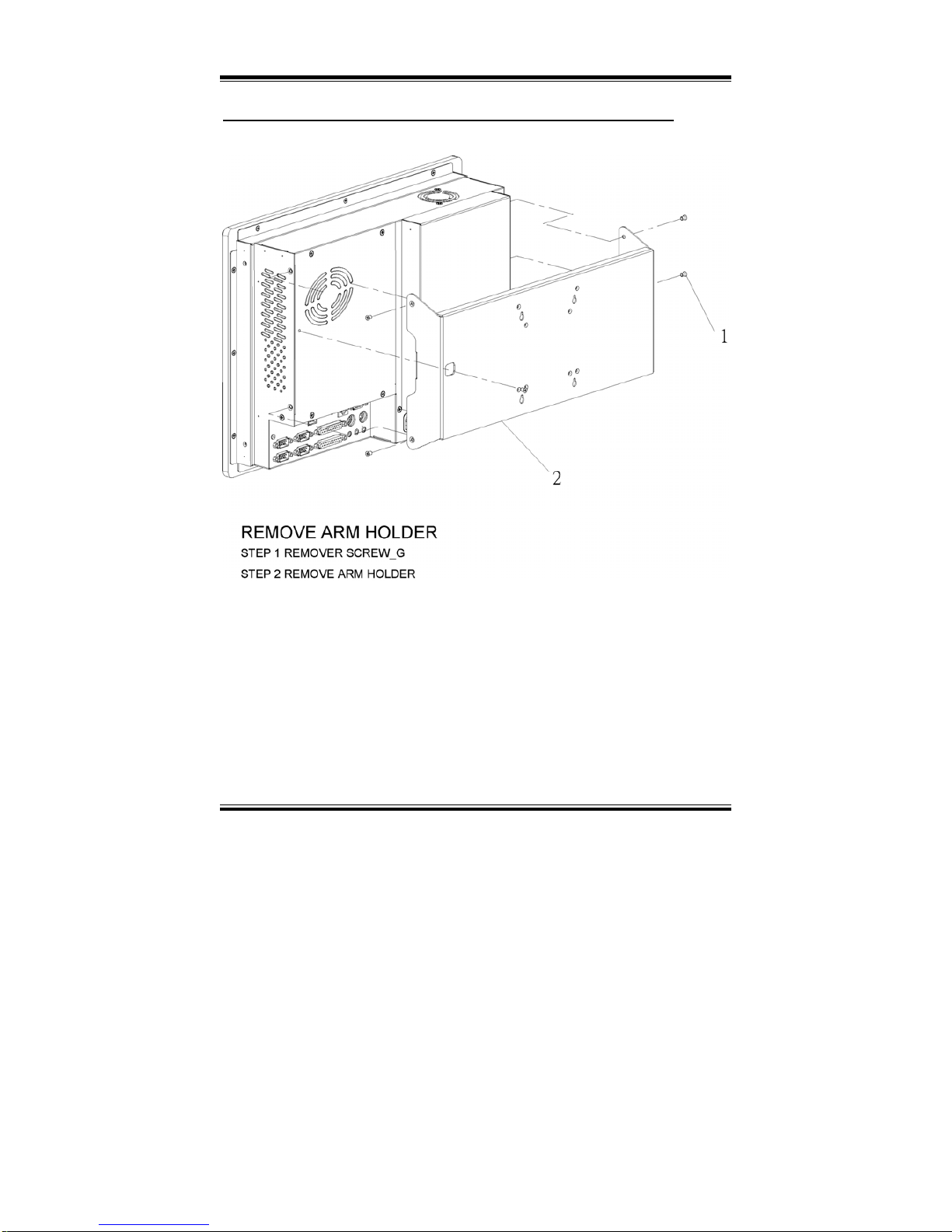
Appendix A System Assembly
Page: A-2
PPC-740X USER
c
S MANUAL
EXPLODED DIAGRAM FOR REMOVING ARM HOLDER
The Arm Holder does not support 3P3I Riser card module and PPC-7407 system.
Page 94
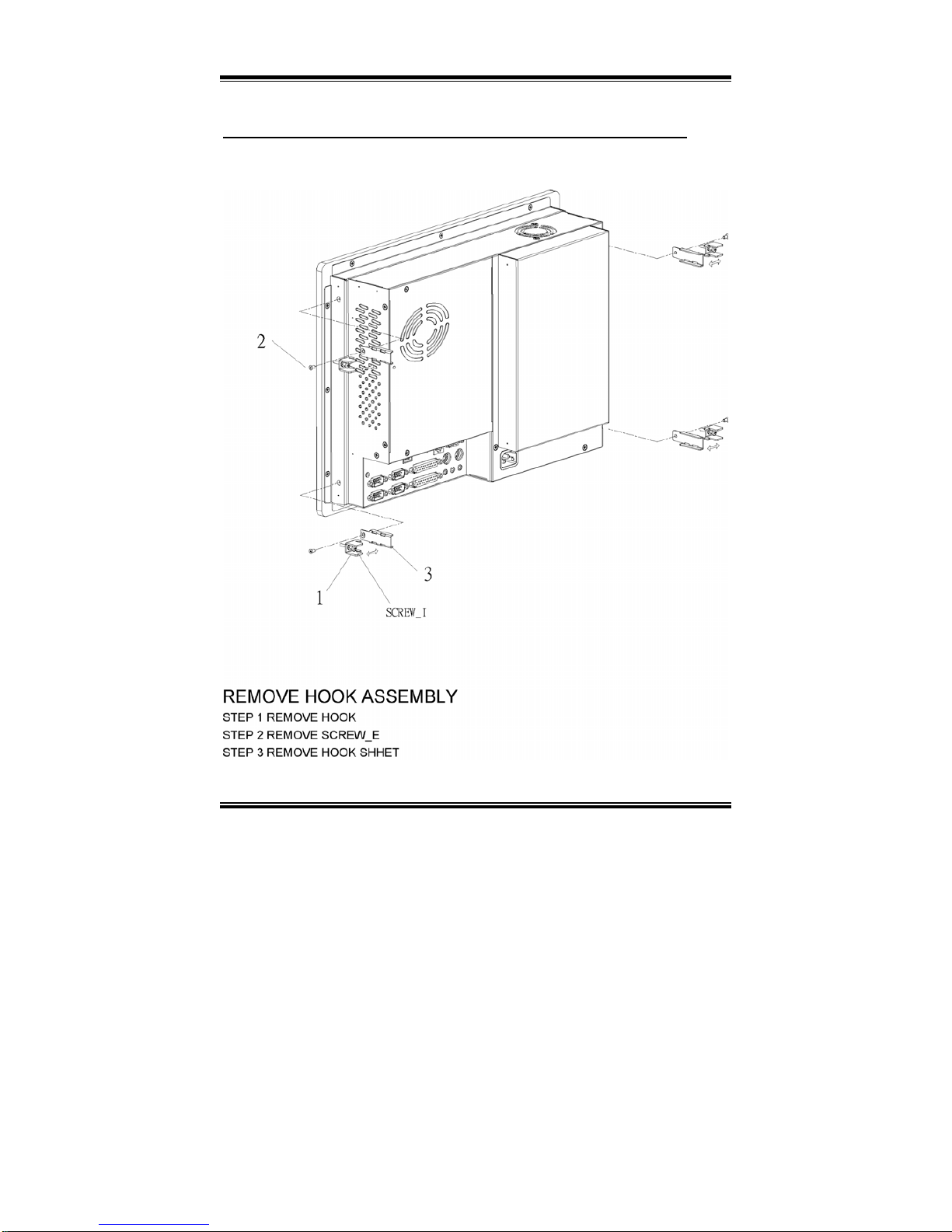
Appendix A System Assembly
PPC-740X USERcS MANUAL
Page: A-3
EXPLODED DIAGRAM FOR REMOVING HOOK HOLDER
Page 95
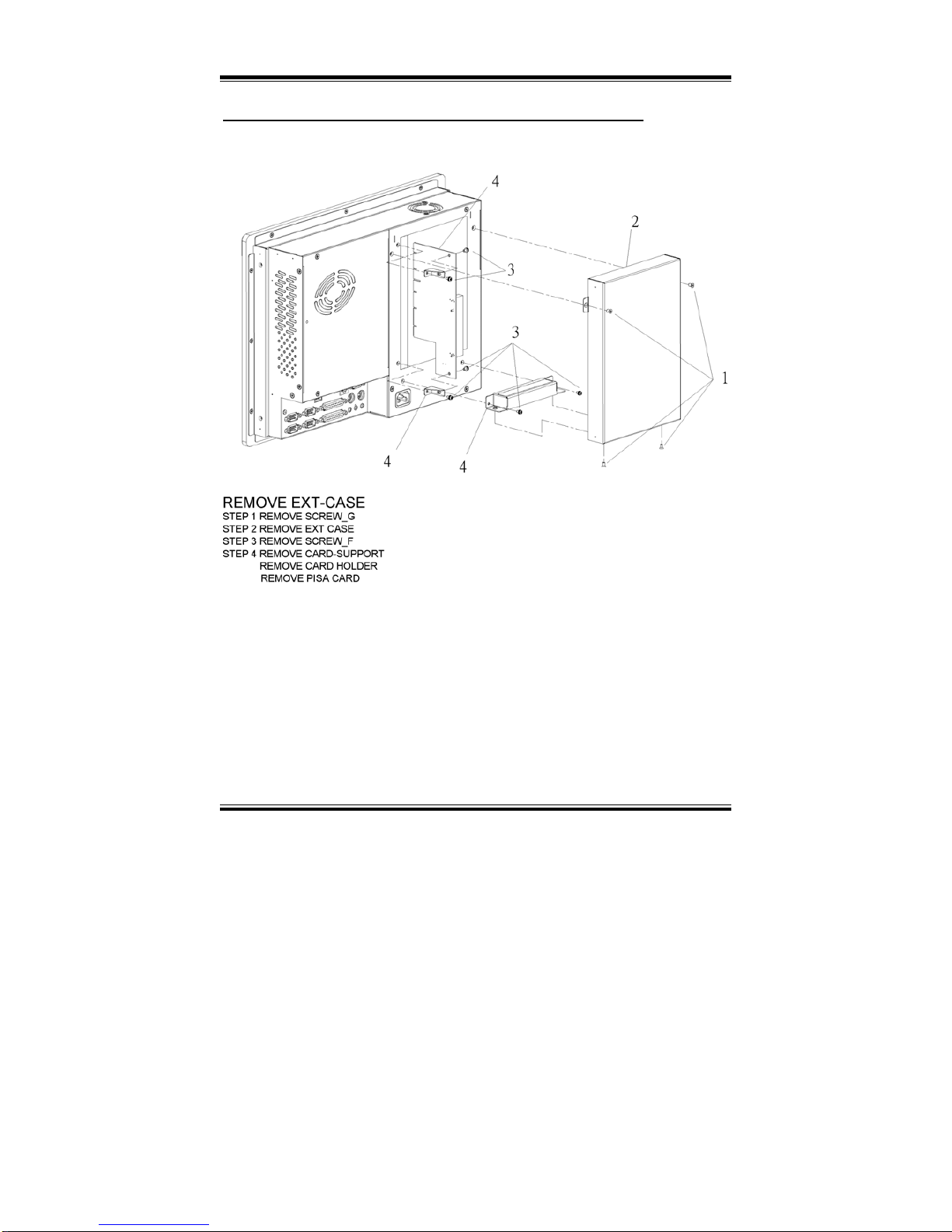
Appendix A System Assembly
Page: A-4
PPC-740X USER
c
S MANUAL
EXPLODED DIAGRAM FOR REMOVING EXT-CASE
Page 96
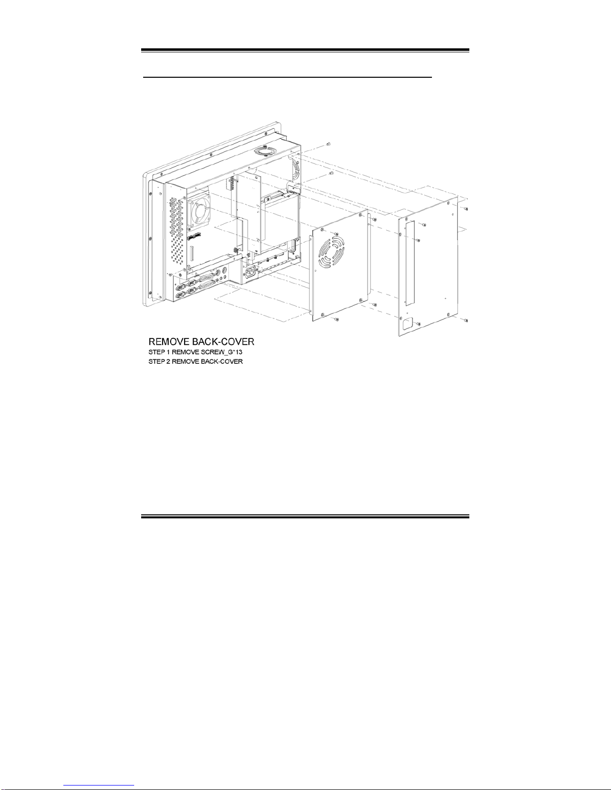
Appendix A System Assembly
PPC-740X USERcS MANUAL
Page: A-5
EXPLODED DIAGRAM FOR REMOVING BACK COVER
Page 97
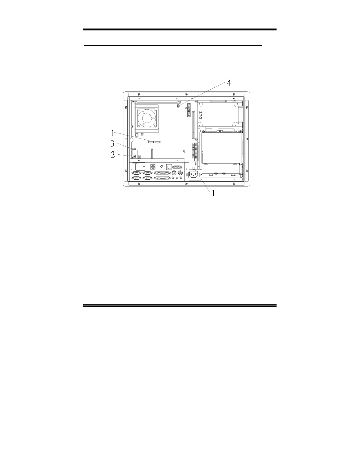
Appendix A System Assembly
Page: A-6
PPC-740X USER
c
S MANUAL
EXPLODED DIAGRAM FOR REMOVING LCD ASSEMBLY
Diagram 1:
Page 98
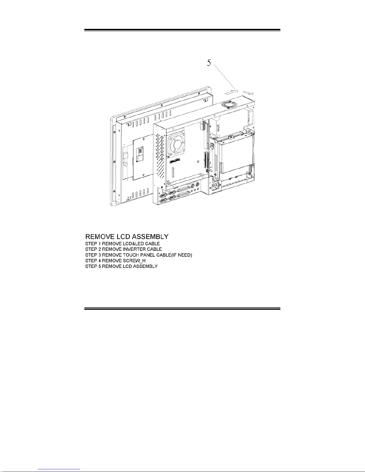
Appendix A System Assembly
PPC-740X USERcS MANUAL
Page: A-7
Diagram 2:
Page 99
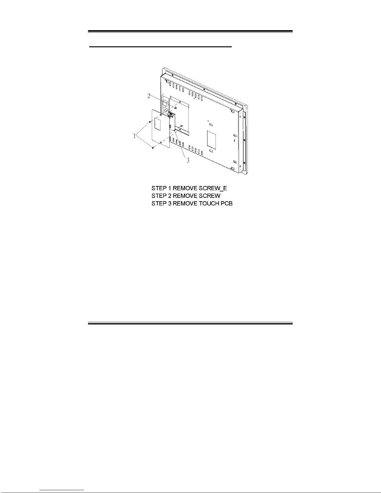
Appendix A System Assembly
Page: A-8
PPC-740X USER
c
S MANUAL
EXPLODED DIAGRAM FOR FRONT PANEL
Diagram 1:
Page 100
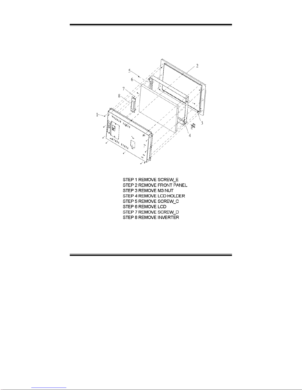
Appendix A System Assembly
PPC-740X USERcS MANUAL
Page: A-9
Diagram 2:
 Loading...