


USER’S
MANUAL
PA-6822
15” POS Terminal
Powered by Intel
®
Celeron®
J1900 Quad-Core
PA-6822 M4

PA-6822 POS System
COPYRIGHT NOTICE & TRADEMARK
All trademarks and registered trademarks mentioned herein are the property of their
respective owners.
This manual is copyrighted in Oct. 2015. You may not reproduce or transmit in any
form or by any means, electronic, or mechanical, including photocopying and
recording.
DISCLAIMER
This user’s manual is meant to assist users in installing and setting up the system. The
information contained in this document is subject to change without any notice.
CE NOTICE
This is a class A product. In a domestic environment this product may cause radio
interference in which case the user may be required to take adequate measures.
PA-6822 Series User Manual
Page 1

FCC NOTICE
This equipment has been tested and found to comply with the limits for a Class A
digital device, pursuant to part 15 of the FCC Rules. These limits are designed to
provide reasonable protection against harmful interference when the equipment is
operated in a commercial environment. This equipment generates, uses, and can
radiate radio frequency energy and, if not installed and used in accordance with the
instruction manual, may cause harmful interference to radio communications.
Operation of this equipment in a residential area is likely to cause harmful interference
in which case the user will be required to correct the interference at his own expense.
You are cautioned that any change or modifications to the equipment not expressly
approve by the party responsible for compliance could void your authority to operate
such equipment.
CAUTION! Danger of explosion if battery is incorrectly replaced. Replace only with the
same or equivalent type recommended by the manufacturer. Dispose of used batteries
according to the manufacturer’s instructions.
WARNING! Some internal parts of the system may have high electrical voltage. And
therefore we strongly recommend that qualified engineers can open and disassemble the
system.The LCD and Touchscreen are easily breakable, please handle them with extra
care.
PA-6822 Series User Manual
Page 2

Contents
PA-6822 SERIES USER MANUAL
Page 3
TABLE OF CONTENTS
CHAPTER 1 INTRODUCTION
1-1 About This Manual…...................................................................
5
1-2 POS System Illustration…............................................................
6
1-3 System Specification….................................................................
8
1-4 Safety Precautions…....................................................................
14
CHAPTER 2 SYSTEM CONFIGURATION
2-1 System External I/O Port & Pin Assignment.…...........................
17
2-2 Main Board Component Locations & Jumper Settings………….
22
2-3 Printer Board Component Locations & Pin Assignment..............
39
2-4 VFD Board Component Locations & Pin Assignment.................
57
2-5 MSR Board Component Locations & Pin Assignment.................
59
CHAPTER 3 SOFTWARE Utilities
3-1 Version List……..…....................................................................
67
3-2 OS API……….............................................................................
68
3-3 Embedded Peripheral Devices………..........................................
90
3-4 Utility Update………...................................................................
154
3-5 BIOS Operation….……...............................................................
158
3-6 Watchdog Timer Configuration…………………………………
192
3-7 BIOS Update Instructions……………………………………….
195
3-8 System Resource Map…………………………………………...
199
CHAPTER 4 SYSTEM DIAGRAMS
Exploded Diagram for Touchscreen & LCD...…………………………
215
Exploded Diagram for System Bottom Case……………………….......
222
Exploded Diagram for System Assembly……………………….............
226
Exploded Diagram for VFD……………………….................................
229
Exploded Diagram for Printer…..………………………........................ 230
Exploded Diagram for MSR & i-Button………..……………………… 237
Exploded Diagram for 2nd Display………………………....................... 240
Exploded Diagram for RFID……………………………………………
241
Exploded Diagram for HDD………………………................................ 242
Exploded Diagram for SSD……………………...................................... 243
APPENDIX A SYSTEM DISPLAY
Installation of 8”/ 10.4” 2nd Display..…………………………………...
245

Page 4
INTRODUCTION
This chapter gives you the information for the PA-6822. It also outlines
the system specifications.
The following sections are included:
About This Manual
POS System Illustration
System Specifications
Safety Precautions
Experienced users can jump to chapter 2 on page 17 for
a quick start.
CHAPTER
1

Chapter 1 Introduction
PA-6822 SERIES USER MANUAL
Page 5
1-1. ABOUT THIS MANUAL
Thank you for purchasing our PA-6822 Series System. The PA-6822 is an updated
system designed to be comparable with the highest performance of IBM AT personal
computers. The PA-6822 provides faster processing speed, greater expandability and
can handle more tasks than before. This manual is designed to assist you how to install
and set up the whole system. It contains four chapters and one appendix. Users can
configure the system according to their own needs.
Chapter 1 Introduction
This chapter introduces you to the background of this manual. It also includes
illustrations and specifications for the whole system. The final section of this chapter
indicates some safety reminders on how to take care of your system.
Chapter 2 System Configuration
This chapter outlines the location of motherboard components and their functions.
You will learn how to set the jumpers and configure the system to meet your own
needs.
Chapter 3 Software Utilities
This chapter contains detailed information for driver installations of the Version List,
OS API, embedded peripheral devices firmware control commands, BIOS setup &
update, Watchdog timer and resource map.
Chapter 4 System Diagrams
This chapter shows the exploded diagrams and part numbers of PA-6822 components.
Appendix A System Display
This appendix illustrates the installation of 8” and 10.4” 2nd Display.

1-2. POS SYSTEM ILLUSTRATION
Top View Bottom View
320
390
Front View Side View
190
24°
28°
Unit: mm
Chapter 1 Introduction
PA-6822 Series User Manual
Page 6

Chapter 1 Introduction
Quarter View
Power LED Ventilation Hole
15” LCD & Bezel-free Touchscreen
VFD Customer Display (Optional)
I/O Port Thermal Printer
(inside the cover) (Optional)
Unit: mm
Open Button of Printer Door
(Both optional)
Vertical i-Button & MSR
Angle Adjustor Foot
Power Button & Side USB
(inside the shield)
Power
LED
Ventilation
Hold
NFC/RFID
Sensor Area
PA-6822 Series User Manual
Page 7

Chapter 1 Introduction
1-3. SYSTEM SPECIFICATIONS
System
CPU Intel® Celeron® J1900 Quad-Core 2.0GHz
Memory 1 x DDR3 SO-DIMM 204-pin socket, up to 8GB
OS Support Windows Embedded 8 Industry Pro Retail
Window Embedded POSReady7
LAN 1 x Giga LAN
Wireless LAN 802.11 b/g/n (Optional)
AP distance 0° 90° 180° 270°
5M -32 dB -27 dB -37 dB -33 dB
10M -43 dB -37 dB -46 dB -44 dB
Note:
1. Test tolerance: ±
5dB
2. AP: ASUS RT-N56U (2 x internal antenna with 3.8 dBi
gain)
Angle: 0°
AP
(Distance)
Angle: 180°Angle: 90°
Angle: 270°
AP
Audio 2W speaker & Line-out Port
BIOS AMI SPI BIOS, 8 Mbits with VGA BIOS
RTC Accuracy 3 days
±
3 seconds
System Weight With power adapter approx. 8 kg
Dimension (W x H x D) 390mm x 320mm x 190mm
Viewing Angel 24~30°
Certificate CE/FCC
PA-6822 Series User Manual
Page 8

Chapter 1 Introduction
Power Consumption (AC):
System
Status
CPU/
HDD/
Memory
VFD Printer COM & USB
Ports to supply
power of Rear I/O
Consumption
OFF
Off 2W
IDLE
Turns on, but
not to execute
extra AP
19.8W
Working
(without
printer)
Standby
25.6W
Working
(with
printer)
without
59.1W
Full Loading
100% loading
of burn-in test
Runs
new
ticker
DC24V
1.4A dummy
load
USB dummy load
500mA x4
68.9W
Certificate CE, CE-LVD, FCC
Type Standard Description
EMI EN 55022 Class A EMS EN 55024 IEC 61000-4-2 ESD 8kV air discharge
4kV contact discharge
IEC 61000-4-3 RS 80~1000MHz, 3V/m, 80% AM(1kHz)
IEC 61000-4-4 EFT AC Power Port: 1kV
DC Power Port: 0.5kV
Signal Ports & Telecommunication
Ports: 0.5kV
IEC 61000-4-5 Surge AC Power Port:
Line to line: 1kV
Line to earth(GND): 2kV
DC Power Port:
Line to earth(GND): 0.5kV
Signal and Telecommunication Port:
Line to GND: 1kV
IEC 61000-4-6 CS 0.15~80MHz, 3Vrms, 80% AM, 1kHz
IEC 61000-4-8 PFMF 50Hz, 1A/m
Voltage Dips > 95% reduction for 0.5 periods
30% reduction for 25 periods
IEC 61000-4-11
Voltage Interruptions > 95% reduction for 250 periods
Power Supply 120 Watt Power adaptor
PA-6822 Series User Manual
Page 9

Chapter 1 Introduction
Display
15” TFT XGA LCD Max. Resolution: 1024 x 768
Signal Interface: TTL (24-bit)
Touchscreen 15” bezel-free
5-wire resistive type
Projected capacitive type
Brightness Resistive Touchscreen:
Minimum Typical Maximum
160 cd/m
2
200 cd/m
2
-
Projected Capacitive Touchscreen:
Minimum Typical Maximum
180 cd/m
2
225 cd/m
2
-
1
2
3
4
5
Environment
Temperature Operating: 0~35°C (32 ~ 95°F)
Storage: -20~60°C (-4 ~ 140°F)
Humidity 20~90%
PA-6822 Series User Manual
Page 10
Chapter 1 Introduction
Optional accessories
MSR & i-Button ISO I ,II, III; JIS I,II and support information key reader
RFID ISO14443A, Mifare, Felica-lite
Fingerprint 8-bit grayscale reader
2nd Display 8” LCD (Resolution: 800 x 600)
10.4” LCD (Resolution: 1024 x 768 or 800 x 600)
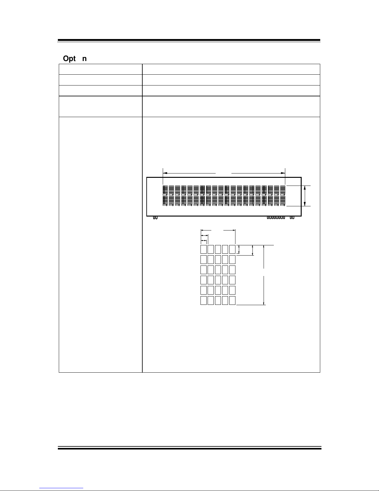
Customer Display Interface: RS-232C Baud Rate: 9600/19200 bps
Placement: 20 columns and 2 lines, each column is 5
x 7 dots
Brightness: cd/m2
Dimensions:
18.2
107.2
0.55
0.75
6.75
3.75
0.8
1.0
Standard Code
CP-437, CP-850, CP-857, CP-865, Katakana
International Characters
USA, FRANCE, GERMANY, UK, DENMARK I,
SWDEN, ITALY, SPAIN, JAPAN, NORWAY,
DENMARK II, RUSSIA, SLAVONIC
PA-6822 Series User Manual
Page 11

Chapter 1 Introduction
Printer
2” or 3” easy loading thermal printer with auto-cutter
Printer:
Items Specifications
Printing method Thermal dot line printing
Printing accuracy 1mm /5M
Paper feed pitch 0.0625 mm
Maximum Paper-Roll
thickness
80mm
Total dots per line &
Printable dots per line
2inch 432 dots;
3inch 576 dots
Maximum print speed 2inch 200 mm/s;
3inch 170 mm/s
Print width 2inch 54 mm;
3inch 72mm
Paper width 2inch 58 +0/-1 mm;
3inch 80 +0/-1 mm
A mm (Printing Width)
2 inch (A:54, C:58, D:2)
3 inch (A:72, C:80, D:4)
D mm
D mm
0
-1 mm (Paper Width)
C
PA-6822 Series User Manual
Page 12

Chapter 1 Introduction
Printer Auto-cutter:
Items Specifications
Paper cutting method Slide cutting
Type of paper cutting Full cut and Partial cut (1.5
±0.5 mm tab left at the center)
Paper curling tendency Fixed blade side and Movable
blade side
Minimum paper core
diameter
φ8 mm (paper thickness: 75µm
or thin)
φ18 (paper thickness: thicker
than 75µm)
Minimum paper cutting
length
10 mm
Cutting processing time Approx. 0.5 s/cycle
Cutting frequency 1 cut/2 s max.
Standard Code
CP-437, CP-850, CP-857, CP-737, CP-852, CP-860,
CP-862, CP-863, CP-865, CP-866, CP-1250,
CP-1251, CP-1252, CP-1253, CP-1254, CP-1257,
Katakana
KANJI
JAPANESE (SHIFT-JIS) C
ode,
TRADITIONAL CHINESE Code
International Characters
USA, FRANCE, GERMANY, UK, DENMARK I,
SWDEN, ITALY, SPAIN I, JAPAN, NORWAY,
DENMARK II, SPAIN II, LATIN AMERICA,
KOREA, RUSSIA, SLAVONIC
PA-6822 Series User Manual
Page 13

Chapter 1 Introduction
1-4. SAFETY PRECAUTIONS
The following messages are safety reminders on how to protect your systems from
damages, and extending the life cycle of the system.
1. Check the Line Voltage
a. The operating voltage for the power supply should be within the range of
100V to 240V AC; otherwise the system may be damaged.
2. Environmental Conditions
a. Place your PA-6822 on a sturdy, level surface. Be sure to allow enough
space around the system to have easy access needs.
b. Avoid installing your PA-6822 Series POS system in extremely hot or cold
places.
c. Avoid exposure to sunlight for a long period of time (for example, in a
closed car in summer time. Also avoid the system from any heating device.).
Or do not use the PA-6822 when it has been left outdoors in a cold winter
day.
d. Bear in mind that the operating ambient temperature is between 0°C and
35°C (32°F and 95°F).
e. Avoid moving the system rapidly from a hot place to a cold place, and vice
versa, because condensation may occur inside the system.
f. Protect your PA-6822 against strong vibrations, which may cause hard disk
failure.
g. Do not place the system too close to any radio-active device. Radio-active
device may cause signal interference.
h. Always shutdown the operation system before turning off the power.
3. Handling
a. Avoid placing heavy objects on the top of the system.
b. Do not turn the system upside down. This may cause the hard drive to
malfunction.
c. Do not allow any objects to fall into this product.
d. If water or other liquid spills into the product, unplug the power cord
immediately.
PA-6822 Series User Manual
Page 14

Chapter 1 Introduction
4. Good Care
a. When the outside case gets stained, remove the stains using neutral washing
agent with a dry cloth.
b. Never use strong agents such as benzene and thinner to clean the surface of
the case.
c. If heavy stains are present, moisten a cloth with diluted neutral washing
agent or alcohol and then wipe thoroughly with a dry cloth.
d. If dust is accumulated on the case surface, remove it by using a special
vacuum cleaner for computers.
PA-6822 Series User Manual
Page 15

Page 2-1
SYSTEM
CONFIGURATION
Helpful information that describes the jumper and connector settings,
component locations, and pin assignment.
Sections included:
External I/O Port Pin Assignment
How to Set Jumpers
Component Locations & Jumper Settings
Mainboard
Printer Board (peripheral device)
VFD Board (peripheral device)
MSR Board (peripheral device)
CHAPTER
2
PA-6822 Series User Manual
Page 16

Chapter 2 System Configuration
2-1. SYSTEM EXTERNAL I/O PORT & PIN ASSIGNMENT
Rear I/O
Option1
Option2
DRW1
USB3
2nd Display
Power
DC IN
COM(4)
LAN
VGA
USB
0
1
2
COM3
COM2
Parallel Port
(LPT, D-sub 25-pin)
COM1 COM4
(2 x RS-232, D-sub 9-pin)
Side I/O
Power USB4
button
PA-6822 Series User Manual
Page 17

Chapter 2 System Configuration
Power Button
To turn on the system, press the power button on the side
of the system briefly.
ACTION ASSIGNMENT
Click 0V
Release +3.3V
DC-IN Port
DC IN: DC Power-In Port (rear IO)
PIN ASSIGNMENT PIN ASSIGNMENT
1 GND 3 +24V
2 GND 4 +24V
VGA Port
VGA: VGA Port, D-Sub 15-pin (rear IO)
PIN ASSIGNMENT PIN ASSIGNMENT
1 RED 9 +5V
2 GREEN 10 GND
3 BLUE 11 NC
4 NC 12 DDCA DATA
5 GND 13 HSYNC
6 GND 14 VSYNC
7 GND 15 DDCA CLK
8 GND
34
12
DC IN
Power
Button
15
610
1115
VGA
PA-6822 Series User Manual
Page 18

Chapter 2 System Configuration
COM Port
COM2, COM3, COM4: D-Sub9 Serial Ports (rear IO)
COM2: Co-lay with COM2-1
COM3: Co-lay with COM3-1
PIN ASSIGNMENT PIN ASSIGNMENT
1 DCD 6 DSR
2 RXD 7 RTS
3 TXD 8 CTS
4 DTR 9 RI/+5V/+12V
selectable (Max.
current: 1A)
5 GND
Note: COM3 & COM3-1 will not function when jumpers
JP20, JP21, JP22 are set as 2-3 connected (i-Button).
Refer to the section i-Button Function Selection for
details. COM4-2 will not function when COM4-1 is
selected as the printer control interface.
LAN Port
LAN: LAN RJ45 Port (rear IO)
PIN ASSIGNMENT PIN ASSIGNMENT
1 MDIP0 5 MDIP2
2 MDIN0 6 MDIN2
3 MDIP1 7 MDIP3
4 MDIN1 8 MDIN3
LAN LED Indicator:
Right Side LED
Yellow Color Blinking LAN Message Active
Off No LAN Message Active
Left Side LED
Green Color On 10/100Mbps LAN Speed Indicator
Orange Color on Giga LAN Speed Indicator
Off No LAN switch/ hub connected.
5
1
9
6
COM2/
COM3/
COM4/
81
Green Yellow
LAN
PA-6822 Series User Manual
Page 19

Chapter 2 System Configuration
Cash Drawer Port
DRW1 is used by default. If you need a second port, adopt the method below.
PIN ASSIGNMENT PIN ASSIGNMENT
1
GND
4 +12V/+24V (Max. current: 1A)
2 Drawer Open 5 NC
3 Drawer Sense 6 GND
DRW1
Open
Write "700"h to I/O port
"588"h
Close
Write "00"h to I/O port
"588"h
USB Port
USB0, USB1, USB2, USB3, USB4: USB Type A Ports
USB0~3: Rear I/O
USB4: Side IO
PIN ASSIGNMENT PIN ASSIGNMENT
1 +5V (Max.
current: 0.5A)
3 D+
2 D- 4 GND
1 4
USB0/
USB1/
USB2/
USB4/
1 4
USB3
PA-6822 Series User Manual
Page 20

Chapter 2 System Configuration
PIN ASSIGNMENT PIN ASSIGNMENT
1 STBJ 14 ALFJ
2 PDR0 15 ERRJ
3 PDR1 16 PARR_INITJ
4 PDR2 17 SLCTINJ
5 PDR3 18 GND
6 PDR4 19 GND
7 PDR5 20 GND
8 PDR6 21 GND
9 PDR7 22 GND
10 ACKJ 23 GND
11 BUSY 24 GND
12 PE 25 GND
13 SLCTJ
113
25 14
LPT
Printer Port (Optional)
LPT: Printer Port, D-Sub 25-pin, co-lay with LPT1
PA-6822 Series User Manual
Page 21

Chapter 2 System Configuration
2-2. MAINBOARD COMPONENT LOCATIONS & JUMPER
SETTINGS
M/B: PB-6822
LVDS1
USB7
J3
JP_VDD1
JP_12
JP_8
JP_9
USB1
JP32
SW1_3
JP19
JP30
USB2
COM1_1
COM4_1
COM2_1
COM3_1
JP_COM4
JP_C
OM3
JP_COM2
JP_COM1
PRT_PWR1
PWR_IN1
VGA1
USB8LAN1
LINE-OUT1
JP31
USB5
SW1
USB6
JI_BUTTON1
PS/2_2
SP1
SPK1
SLOT1
COM4_2
JP20
JP21
JP22
COM2
COM3
DC5V_PWR1
JP37
JP29
JP5
DC12V_PWR1
LPT1
J2
SATA2
SATA1
JPWR_4P2
JPWR_4P1
TOUCH3
JP14
JP15
JINVDRV1
JINV4
JP4
JP3
JP38JP39
30
291
2
Battery
1
1
1
1
1 31 4
1
6
5
10
14
1
1
1
1
1 21 21 2
5 65 65 6
526
1
1
1
1
1
112
910
6
1
1
6
1
1
15
15
1
5
1
5
1 15 17 51
2 16 18 52
1
4
1
127
8
1
10
5
6
1
6
1
1
1
2
255
6
5
6
6
1
1
4
1
2
6
10
5
10
5
26
13
14
1
1 4
1 4
1 7
1 7
Intel
®
Celeron® J1900
Quad-Core
DIMM1
1
2
71
72
73
74
203
204
ESATA1
DRW1
15
PB-6822 Mainboard Component Locations
PA-6822 Series User Manual
Page 22

Chapter 2 System Configuration
SLOT2
1
15
17
51
2
16
18
52
PB-6822 Mainboard Component Locations - Rear
PA-6822 Series User Manual
Page 23

Chapter 2 System Configuration
How to Set Jumpers
You can configure your board by setting the jumpers. A jumper consists of two or three
metal pins with a plastic base mounted on the card, and by using a small plastic "cap",
also known as the jumper cap (with a metal contact inside), you are able to connect the
pins. So you can set-up your hardware configuration by "opening" or "closing" pins.
Jumpers can be combined into sets that called jumper blocks. When jumpers are all in
the block, you have to put them together to set up the hardware configuration. The
figure below shows what this looks like.
Jumpers & caps
If a jumper has three pins for example, labelled PIN1, PIN2, and PIN3. You can
connect PIN1 & PIN2 to create one setting and shorting. You can either connect PIN2
& PIN3 to create another setting. The same jumper diagrams are applied all through
this manual. The figure below shows what the manual diagrams look and what they
represent.
PA-6822 Series User Manual
Page 24

Chapter 2 System Configuration
Jumper diagrams
Jumper settings
PA-6822 Series User Manual
Page 25

Chapter 2 System Configuration
COM Port RI & Voltage Selection
JP_COM1, JP_COM2, JP_COM3, JP_COM4: Pin-headers on board
SELECTION JUMPER
SETTING
JUMPER ILLUSTRATION
RI 1-2
5
6
1
2
JP_COM1
5
6
1
2
JP_COM2
5
6
1
2
JP_COM3
5
6
1
2
JP_COM4
+12V 3-4
5
6
1
2
JP_COM1
5
6
1
2
JP_COM2
5
6
1
2
JP_COM3
5
6
1
2
JP_ COM4
+5V 5-6
5
6
1
2
JP_COM1
5
6
1
2
JP_COM2
5
6
1
2
JP_COM3
5
6
1
2
JP_ COM4
Caution:
1.
Voltage of external COM 1~ 4 ports are made to control on BIOS for your convenience.
The corresponding jumpers JP_COM1~4 are set open (no connection) by default;
refer to Voltage Adjust Configuration for detailed jumper setting (BIOS default at Disable).
2.
JP_COM1~4 are enabled when COM1~4 voltage adjustment is disabled on BIOS
3.
Voltage of COM port is adjustable by BIOS or jumpers. Either way cannot be applied
simultaneously in case of system error, component damage or serious boot failure.
PS: COM4 is optional
PA-6822 Series User Manual
Page 26
Chapter 2 System Configuration
COM Connector
COM1-1, COM2-1, COM3-1, COM4-1, COM4-2: COM Connectors
PIN ASSIGNMENT PIN ASSIGNMENT
1 DCD 6 DSR
2 RXD 7 RTS
3 TXD 8 CTS
4 DTR 9 RI/+5V/+12V selectable
(Max. current: 1A)
5 GND 10 NC
Note:
Each COM connector is selectable for RI/+5V/+12V.
For details, refer to COM Port RI & Voltage Selection.
I-Button Connector
JI_BUTTON1: i-Button Connector
PIN ASSIGNMENT
1 COM3_DTR_R_I
2 COM3_RXD_R_I
I-Button Function Selection
JP20, JP21, JP22: i-Button Function Connectors
SELECTION JUMPER SETTING JUMPER ILLUSTRATION
COM 3 1-2
1
3
JP20/JP21/JP22/
i-Button* 2-3
1
3
JP20/JP21/JP22/
Note: Manufacturing Default is COM3.
*COM3 & COM3-1 will not function when jumpers JP20, JP21 & JP22 are set as “i-Button.”
1
2
JI_BUTTON1
51
10
6
COM1-1/
COM2-1/
COM3-1/
COM4-1/
6
10
1
5
COM4-2/
PA-6822 Series User Manual
Page 27

Chapter 2 System Configuration
Cash Drawer Control Selection
JP37: DRW1 control connector
SELECTION JUMPER SETTING JUMPER ILLUSTRATION
DRW1 ON
2-3
Cash Drawer Power Selection
JP29: DRW1
SELECTION JUMPER SETTING JUMPER ILLUSTRATION
+24V 1-2
+12V 2-3
Note: Manufacturing Default is open.
PA-6822 Series User Manual
Page 28

Chapter 2 System Configuration
USB Connector
USB1, USB2, USB6, USB7: USB connector
PIN ASSIGNMENT
1 5V (Maximum current: 0.5A)
2 D-
3 D+
4 GND
5 GND
Note: USB1 would be used when jumpers
JP14 & JP15 are set as 1-2 (short)
connected.
LED Connector
LED1-1: Power indication LED connector
PIN ASSIGNMENT
1 GND
2 PWR_LED
2 1
LED1-1
15
USB1/
USB2/
USB7/
USB6
Inverter Connector
JINV4: Inverter connectors
PIN ASSIGNMENT
1 +12V
2 +12V
3 GND
4 BRCTR
5 GND
6 LVDS_BKLTEN
16
JINV4
PA-6822 Series User Manual
Page 29

Chapter 2 System Configuration
Power Connector
DC12V_PWR1: DC 12Voltage Provider Connector
PIN ASSIGNMENT
1 VCC12
2 GND
3 VCC12
DC5V_PWR1: DC 5Voltage Provider Connector
PIN ASSIGNMENT
1 5V
2 GND
Power for Thermal Printer Connector
PRT_PWR1: Power for Thermal Printer Connector
PIN ASSIGNMENT
1 VCC24SB
2 VCC24SB
3 GND
4 GND
External Speaker Connector
SPK1: External speaker connector
PIN ASSIGNMENT
1 SPK_GND
2 SPK_OUT
1 3
DC12V_PWR1
1 4
PRT_PWR1
12
SPK1
12
DC5V_PWR1
PA-6822 Series User Manual
Page 30

Chapter 2 System Configuration
LED Backlight Power Control Selection
JP12: LED backlight power control connectors
(for LED backlight panel without power driver built-in)
SELECTION JUMPER SETTING JUMPER ILLUSTRATION
JP12
65
JP12
Note: Manufacturing Default is LED.
LED Backlight Power Connector
JINVDRV1: LED backlight power connector
PIN ASSIGNMENT
1 VCC
2 GND
Note: JINVDRV1 will not function when
JP38 & JP39 are set as “RS-232”
interface.
12
JINVDRV1
65
PA-6822 Series User Manual
Page 31

Chapter 2 System Configuration
Panel Resolution Selection
JP8, JP9: Panel resolution control connectors
SELECTION JUMPER
SETTING
JUMPER ILLUSTRATION
15”
1024 x 768
(24 bit)
JP8: 1-3, 4-6
JP9: 3-5, 4-6
21
65
JP8
21
65
JP9
10.4”
1024 x 768
(18 bit)
JP8: 3-5, 2-4
JP9:3-5, 4-6
21
65
JP8
21
65
JP9
10.4”
800 x 600
(18bit)
JP8: 3-5, 4-6
JP9: 3-5, 4-6
21
65
JP8
21
65
JP9
Note: Manufacturing Default is 15”, 1024 x 768
PA-6822 Series User Manual
Page 32

Chapter 2 System Configuration
LVDS Connector
LVDS1: LVDS Connector
PIN ASSIGNMENT PIN ASSIGNMENT
1 LVDS_VCC 16 LVDS_CLKA_D+
2 GND 17 VDS_CLKA_D-
3 NC 18 GND
4 NC 19 LVDS_A2_D+
5 GND 20 LVDS_A2_D-
6 LVDS_B2_D- 21 GND
7 LVDS_B2_D+ 22 LVDS_A1_D+
8 GND 23 LVDS_A1_D-
9 LVDS_B1_D- 24 GND
10 LVDS_B1_D+ 25 LVDS_A0_D+
11 LVDS_B3_D+ 26 LVDS_A0_D-
12 LVDS_B3_D- 27 LVDS_A3_D+
13 LVDS_B0_D+ 28 LVDS_A3_D-
14 LVDS_B0_D- 29 LVDS_VCC
15 GND 30 LVDS_VCC
2
1 29
30
LVDS1
PA-6822 Series User Manual
Page 33

Chapter 2 System Configuration
Touch Panel Signal Interface Selection
JP14, JP15, JP38, JP39: Control connectors for touch panel signal interface
SELECTION JUMPER
SETTING
JUMPER ILLUSTRATION
USB1
Connector
JP14: 1-2
JP15: 1-2
JP38: 2-3
JP39: 2-3
1 3
JP14
1 3
JP15
3
1
JP38
3
1
JP39
USB
Interface
JP14: 2-3
JP15: 2-3
JP38: 2-3
JP39: 2-3
1 3
JP14
1 3
JP15
3
1
JP38
3
1
JP39
RS-232
Interface
JP14: 1-2
JP15: 1-2
JP38: 1-2
JP39: 1-2
1 3
JP14
1 3
JP15
3
1
JP38
3
1
JP39
Note: 1. Manufacturing Default is USB.
2. The COM2 & COM2-1 connector will not function when JP38 & JP39 are set
as 1-2 connected.
3. USB1 connector when JP14 & JP15 are set as 1-2 connected.
Touch Panel Connector
TOUCH3: Touch panel connectors
PIN ASSIGNMENT PIN ASSIGNMENT
1 LR (Low Right) 4 UR (Up Right)
2 LL (Low Left) 5 UL (Up Left)
3 Probe
TOUCH3
5
1
PA-6822 Series User Manual
Page 34

Chapter 2 System Configuration
Clear CMOS Data Selection
JP3: Clear CMOS data selection
SELECTION JUMPER SETTING JUMPER ILLUSTRATION
Normal Open
1
JP3
Clear CMOS* 1-2
1
JP3
Note: Manufacturing Default is Normal.
*To clear CMOS data, you must power-off the computer and set the jumper to “Clear CMOS” as
illustrated above. After five to six seconds, set the jumper back to “Normal” and power-on the
computer.
Printer Connector
LPT1: Printer connector
PIN ASSIGNMENT PIN ASSIGNMENT
1 STBJ 14 ALFJ
2 PDR0 15 ERRJ
3 PDR1 16 PAR_INITJ
4 PDR2 17 SLCTINJ
5 PDR3 18 GND
6 PDR4 19 GND
7 PDR5 20 GND
8 PDR6 21 GND
9 PDR7 22 GND
10 ACKJ 23 GND
11 BUSY 24 GND
12 PE 25 GND
13 SLCTJ 26 NC
26
13
14
1
LPT1
PA-6822 Series User Manual
Page 35

Chapter 2 System Configuration
SATA & SATA Power Connector
SATA1, SATA2: Serial ATA connectors
PIN ASSIGNMENT PIN ASSIGNMENT
1 G1 5 RX-
2 TX+ 6 RX+
3 TX- 7 G3
4 G2
Note: SATA1 only supports the optional RAID
function on board.
JPWR_4P1, JPWR_4P2: Serial ATA power connectors
PIN ASSIGNMENT
1 VCC
2 GND
3 GND
4 VCC12
Note: JPWR_4P1 only supports the
optional RAID function on board.
1 7
SATA1/
SATA2/
1 4
JPWR_4P1/
JPWR_4P2/
MSR/Card Reader Connector
PS/2_2: MSR/Card reader connectors
PIN ASSIGNMENT
1 KB_CLK (Output)
2 KB_CLK_C (Input)
3 KB_DATA_C (Input)
4 KB_DATA (Output)
5 +5V
6 GND
6
1
PS/2_2
PA-6822 Series User Manual
Page 36

Chapter 2 System Configuration
Mini-PCIe / mSATA Connector
SLOT1: Mini-PCIe connector, not support USB function
PIN ASSIGNMENT PIN ASSIGNMENT
1 WAKE# 27 GND
2 +3.3V 28 +1.5V
3 Reserved 29 GND
4 GND 30 SMB_CLK
5 Reserved 31 PETn2
6 +1.5V 32 SMB_DATA
7 CLKREQ# 33 PETp2
8 Reserved 34 GND
9 GND 35 GND
10 Reserved 36 NC
11 REFCLK1- 37 GND
12 Reserved 38 NC
13 REFCLK1+ 39 +3.3V
14 Reserved 40 GND
15 GND 41 +3.3V
16 Reserved 42 Reserved
17 Reserved 43 GND
18 GND 44 Reserved
19 Reserved 45 NC
20 Reserved 46 Reserved
21 GND 47 NC
22 PERST# 48 +1.5V
23 PERn2 49 NC
24 +3.3SB 50 GND
25 PERp2 51 Reserved
26 GND 52 +3.3V
12151617
18
51
52
SLOT1
PA-6822 Series User Manual
Page 37

Chapter 2 System Configuration
SLOT2: Mini-PCIe or mSATA connector, support USB function
PIN ASSIGNMENT PIN ASSIGNMENT
1 WAKE# 27 GND
2 +3.3V 28 +1.5V
3 Reserved 29 GND
4 GND 30 SMB_CLK
5 Reserved 31 PETn0/SATA1_TX-
6 +1.5V 32 SMB_DATA
7 CLKREQ# 33 PETp0/SATA1_TX+
8 Reserved 34 GND
9 GND 35 GND
10 Reserved 36 USB_D-
11 REFCLK0- 37 GND
12 Reserved 38 USB_D+
13 REFCLK0+ 39 +3.3V
14 Reserved 40 GND
15 GND 41 +3.3V
16 Reserved 42 Reserved
17 Reserved 43 GND
18 GND 44 Reserved
19 Reserved 45 NC
20 Reserved 46 Reserved
21 GND 47 NC
22 PERST# 48 +1.5V
23 PERn0/SATA1_RX+ 49 NC
24 +3.3SB 50 GND
25 PERp0/SATA1_RX- 51 Reserved
26 GND 52 +3.3V
12
1516
1718
5152
SLOT2
PA-6822 Series User Manual
Page 38

Chapter 2 System Configuration
2-3. PRINTER BOARD COMPONENT LOCATIONS & PIN
ASSIGNMENT
Printer Board: PDAC-3100
CN5
CN8
CN7
CN6
CN3
CN1
14
1
1
13
7
1
12
CN2
1
50
1
5
1
4
PDAC-3100 Printer Board Component Locations
PA-6822 Series User Manual
Page 39

Chapter 2 System Configuration
Power Supply Connector
CN1: Power supply wafer
PIN ASSIGNMENT
1 +24V
2 +24V
3 GND
4 GND
RS-232 Interface Connector
CN7: RS-232 interface connector
PIN ASSIGNMENT PIN ASSIGNMENT
1 TXD 5 DTR
2 RXD 6 DSR
3 RTS 7 GND
4 CTS
4
1
CN1
1
7
CN7
PA-6822 Series User Manual
Page 40

Chapter 2 System Configuration
Auto-Cutter Connector
CN3: Auto-cutter wafer
PIN ASSIGNMENT FUNCTION
1 NC Unused
2 Vcs Power supply of the home
position sensor
3 GND GND of the home position
sensor
4 CUTS Signal of the hom position
sensor
5 2B-1 Auto-cutter motor drive signal
6 2B-2 Auto-cutter motor drive signal
7 2A-1 Auto-cutter motor drive signal
8 2A-2 Auto-cutter motor drive signal
9 1B-1 Auto-cutter motor drive signal
10 1B-2 Auto-cutter motor drive signal
11 1A-1 Auto-cutter motor drive signal
12 1A-2 Auto-cutter motor drive signal
USB Connector
CN8: USB Connector
PIN ASSIGNMENT PIN ASSIGNMENT
1 Vbus 4 NC
2 D- 5 GND
3 D+
1
5
CN8
1
12
CN3
PA-6822 Series User Manual
Page 41

Chapter 2 System Configuration
Thermal Head/Motor/Sensor Connector
CN2: Thermal head/motor/sensor connector
PIN ASSIGNMENT FUNCTION
1 24V Head drive power
2 24V Head drive power
3 24V Head drive power
4 24V Head drive power
5 24V Head drive power
6 24V Head drive power
7 DAT Print data output
8 CLK Synchronizing signal for print
data transfer
9 GND Head GND
10 GND Head GND
11 GND Head GND
12 GND Head GND
13 GND Head GND
14 GND Head GND
15 NC Unused
16 DST4 Head strobe signal
17 DST3 Head strobe signal
18 3.3V Logic Power
19 GND Thermistor GND
20 GND Thermistor GND
21 TH Thermistor signal
22 NC Unused
23 DST2 Head strobe signal
24 DST1 Head strobe signal
25 GND Head GND
26 GND Head GND
27 GND Head GND
28 GND Head GND
29 GND Head GND
1
50
CN2
PA-6822 Series User Manual
Page 42

Chapter 2 System Configuration
PIN ASSIGNMENT FUNCTION
30 GND Head GND
31 LATCH Print data latch
32 24V Head drive power
33 24V Head drive power
34 24V Head drive power
35 24V Head drive power
36 24V Head drive power
37 24V Head drive power
38 NC Unused
39 PS Signal of the out-of-paper
sensor
40 Vps Power supply of the out-of-
paper sensor
41 GND GND of the platen position/
out-of-paper sensor
42 HS Signal of the platen position
sensor
43 NC Unused
44 FG Frame GND
45 FG Frame GND
46 NC Unused
47 2A Motor drive signal
48 1B Motor drive signal
49 1A Motor drive signal
50 2B Motor drive signal
PA-6822 Series User Manual
Page 43

Chapter 2 System Configuration
Terminal Assignment Connector
CN5: Terminal assignment connector
PIN ASSIGNMENT FUNCTION
1 FEED Feed signal
2 RESET Reset signal
3 GND GND
4 ST1 Status signal
5 ST2
Status signal
6 ST3
Status signal
7 ST4
Status signal
8 GND GND
9 DRS Drawer sensor signal
10 DSW Drawer switch signal
11 Vdu Drive terminal for the drawer
(Vp side)
12 GNDdu Drive terminal for the drawer
(GND side)
13 GND GND
14 NC Unused
14
1
CN5
PA-6822 Series User Manual
Page 44

Chapter 2 System Configuration
Printer Board: MB-10305%5&
1
1
5
13
4
CN3
CN2
4
14
1
1
1
50
12
1
1
9 10
2
CN1
CUT_CN1
PRINT_CN1
COM1
USB_CN1
24V_CN1
MB-1030 Printer Board Component Locations
PA-6822 Series User Manual
Page 45

Chapter 2 System Configuration
Power Supply Connector
24V_CN1: Power Supply Wafer
PIN ASSIGNMENT
1 GND
2 GND
3 +24V
4 +24V
RS-232 Interface Connector
COM1: RS-232 Interface Connector
PIN ASSIGNMENT PIN ASSIGNMENT
1
NC
6
DSR /CTS
2 RXD 7
RTS
3 TXD 8
CTS
4 DTR /RTS 9
NC
5 GND 10
NC
4
1
24V_CN1
1
9 10
2
COM1
PA-6822 Series User Manual
Page 46

Chapter 2 System Configuration
Thermal Head/Motor/Sensor Connector
PRINT_CN1: Thermal head/motor/sensor connector
PIN ASSIGNMENT FUNCTION
1 24V Head drive power
2 24V Head drive power
3 24V Head drive power
4 24V Head drive power
5 24V Head drive power
6 24V Head drive power
7 DAT Print data output
8 CLK Synchronizing signal for print
data transfer
9 GND Head GND
10 GND Head GND
11 GND Head GND
12 GND Head GND
13 GND Head GND
14 GND Head GND
15 NC Unused
16 DST4 Head strobe signal
17 DST3 Head strobe signal
18 3.3V Logic Power
19 GND Thermistor GND
20 GND Thermistor GND
21 TH Thermistor signal
22 NC Unused
23 DST2 Head strobe signal
24 DST1 Head strobe signal
25 GND Head GND
26 GND Head GND
27 GND Head GND
28 GND Head GND
29 GND Head GND
1
50
PRINT_CN1
PA-6822 Series User Manual
Page 47

Chapter 2 System Configuration
PIN ASSIGNMENT FUNCTION
30 GND Head GND
31 LATCH Print data latch
32 24V Head drive power
33 24V Head drive power
34 24V Head drive power
35 24V Head drive power
36 24V Head drive power
37 24V Head drive power
38 NC Unused
39 PS Signal of the out-of-paper
sensor
40 Vps Power supply of the out-of-
paper sensor
41 GND GND of the platen position/
out-of-paper sensor
42 HS Signal of the platen position
sensor
43 NC Unused
44 FG Frame GND
45 FG Frame GND
46 NC Unused
47 2A Motor drive signal
48 1B Motor drive signal
49 1A Motor drive signal
50 2B Motor drive signal
PA-6822 Series User Manual
Page 48

Chapter 2 System Configuration
Auto-Cutter Connector
CUT_CN1: Auto-cutter Connector
PIN ASSIGNMENT FUNCTION
1 NC Unused
2 Vcs Power supply of the home
position sensor
3 GND GND of the home position sensor
4 CUTS Signal of the hom position sensor
5 2B-1 Autocutter motor drive signal
6 2B-2 Autocutter motor drive signal
7 2A-1 Autocutter motor drive signal
8 2A-2 Autocutter motor drive signal
9 1B-1 Autocutter motor drive signal
10 1B-2 Autocutter motor drive signal
11 1A-1 Autocutter motor drive signal
12 1A-2 Autocutter motor drive signal
Paper-Near-END Sensor Connector
CN2: Paper-near-end sensor connector
PIN ASSIGNMENT FUNCTION
1 Vns Power supply of the near end
sensor
2 NS Signal of the near end sensor
3 GND GND of the near end sensor
12
1
CUT_CN1
13
CN2
PA-6822 Series User Manual
Page 49

Chapter 2 System Configuration
USB Interface Connector
USB_CN1: USB interface connector
PIN ASSIGNMENT PIN ASSIGNMENT
1 Vbus 4 GND
2 D- 5 GND
3 D+
Terminal Assignment Connector
CN1: Terminal assignment connector
PIN ASSIGNMENT FUNCTION
1 FEED Feed signal
2 RESET Reset signal
3 GND GND
4 ST1 Status signal
5 ST2
Status signal
6 ST3
Status signal
7 ST4
Status signal
8 GND GND
9 DRS Drawer sensor signal
10 DSW Drawer switch signal
11 Vdu Drive terminal for the drawer
(Vp side)
12 GNDdu Drive terminal for the drawer
(GND side)
13 GND GND
14 NC Unused
1
5
USB_CN1
14
1
CN1
PA-6822 Series User Manual
Page 50

Chapter 2 System Configuration
Printer Board: MB-1011 & MB-1013
CN7
CN3
CN2
CN5
CN1
1
1
14
1
1
12
50
7
4
1
MB-1011
MB-1013
CN8
1
5
MB-1011 & MB-1013 Printer Board Component Locations
PA-6822 Series User Manual
Page 51

Chapter 2 System Configuration
Power Supply Connector
CN1: Power supply wafer
PIN ASSIGNMENT
1 GND
2 GND
3 +24V
4 +24V
RS-232 Interface Connector
CN7: RS-232 interface connector
PIN ASSIGNMENT PIN ASSIGNMENT
1 TXD 5
DTR
2 RXD 6
DSR
3 RTS 7
GND
4 CTS
4
1
CN1
1
7
CN7
PA-6822 Series User Manual
Page 52

Chapter 2 System Configuration
Thermal Head/Motor/Sensor Connector
CN2: Thermal head/motor/sensor connector
PIN ASSIGNMENT FUNCTION
1 24V Head drive power
2 24V Head drive power
3 24V Head drive power
4 24V Head drive power
5 24V Head drive power
6 24V Head drive power
7 DAT Print data output
8 CLK Synchronizing signal for print
data transfer
9 GND Head GND
10 GND Head GND
11 GND Head GND
12 GND Head GND
13 GND Head GND
14 GND Head GND
15 NC Unused
16 DST4 Head strobe signal
17 DST3 Head strobe signal
18 3.3V Logic Power
19 GND Thermistor GND
20 GND Thermistor GND
21 TH Thermistor signal
22 NC Unused
23 DST2 Head strobe signal
24 DST1 Head strobe signal
25 GND Head GND
26 GND Head GND
27 GND Head GND
28 GND Head GND
29 GND Head GND
1
50
CN2
PA-6822 Series User Manual
Page 53

Chapter 2 System Configuration
PIN ASSIGNMENT FUNCTION
30 GND Head GND
31 LATCH Print data latch
32 24V Head drive power
33 24V Head drive power
34 24V Head drive power
35 24V Head drive power
36 24V Head drive power
37 24V Head drive power
38 NC Unused
39 PS Signal of the out-of-paper
sensor
40 Vps Power supply of the out-of-
paper sensor
41 GND GND of the platen position/
out-of-paper sensor
42 HS Signal of the platen position
sensor
43 NC Unused
44 FG Frame GND
45 FG Frame GND
46 NC Unused
47 2A Motor drive signal
48 1B Motor drive signal
49 1A Motor drive signal
50 2B Motor drive signal
PA-6822 Series User Manual
Page 54

Chapter 2 System Configuration
Auto-Cutter Connector
CN3: Auto-cutter Connector
PIN ASSIGNMENT FUNCTION
1 NC Unused
2 Vcs Power supply of the home
position sensor
3 GND GND of the home position sensor
4 CUTS Signal of the hom position sensor
5 2B-1 Autocutter motor drive signal
6 2B-2 Autocutter motor drive signal
7 2A-1 Autocutter motor drive signal
8 2A-2 Autocutter motor drive signal
9 1B-1 Autocutter motor drive signal
10 1B-2 Autocutter motor drive signal
11 1A-1 Autocutter motor drive signal
12 1A-2 Autocutter motor drive signal
USB Interface Connector
CN8: USB interface connector
PIN ASSIGNMENT
1 Vbus
2 D-
3 D+
4 GND
5 GND
12
1
CN3
1
5
CN8
PA-6822 Series User Manual
Page 55

Chapter 2 System Configuration
Terminal Assignment Connector
CN5: Terminal assignment connector
PIN ASSIGNMENT FUNCTION
1 FEED Feed signal
2 RESET Reset signal
3 GND GND
4 ST1 Status signal
5 ST2 Status signal
6 ST3 Status signal
7 ST4 Status signal
8 GND GND
9 DRS Drawer sensor signal
10 DSW Drawer switch signal
11 Vdu Drive terminal for the drawer
(Vp side)
12 GNDdu Drive terminal for the drawer
(GND side)
13 GND GND
14 NC Unused
1
14
CN5
PA-6822 Series User Manual
Page 56

Chapter 2 System Configuration
2-4. VFD BOARD COMPONENT LOCATIONS & PIN ASSIGNMENT
VFD Board: MB-4103, LD720
JP12V
CN1
1
1
16
MB-4103 & LD720 VFD Board Component Locations
PA-6822 Series User Manual
Page 57

Chapter 2 System Configuration
Power Switch Selection
JP12V: Power Switch Selection
SELECTION JUMPER SETTING JUMPER ILLUSTRATION
OFF 1-2
3
1
JP12V
ON 2-3
3
1
JP12V
Note: Manufacturing Default is ON.
RS-232 Serial Interface Connector
CN1: RS-232 serial interface wafer
PIN ASSIGNMENT PIN ASSIGNMENT
1 GND 9 NC
2 TXD 10 NC
3 RXD 11 NC
4 DTR 12 NC
5 DSR 13 NC
6 RTS 14 NC
7 CTS 15 NC
8 +12V/+5V 16 NC
1
16
CN1
PA-6822 Series User Manual
Page 58

Chapter 2 System Configuration
2-5. MSR BOARD COMPONENT LOCATIONS & PIN ASSIGN-
MENT
ID TECH
1
7
CN
ID-TECH MSR Board Component Locations
Main Connector
CN:
PIN ASSIGNMENT PIN ASSIGNMENT
1 Chassis Ground 5
K-CLK
(Computer connections)
2 P-CLK
(Keyboard connections)
6 K-DATA
(Computer connections)
3 P-DATA
(Keyboard connections)
7 GND
4 +5V Vcc
1
7
CN
PA-6822 Series User Manual
Page 59

Chapter 2 System Configuration
SYSKING
112
CN
SYSKING MSR Board Component Locations
Main Connector
CN:
PIN ASSIGNMENT PIN ASSIGNMENT
1 +5V Vcc 7 NC
2 K-DATA
(Host to MSR)
8 NC
3 K-CLK
Host to MSR
9 NC
4 P-DATA
(MSR to Keyboard)
10 NC
5 P-CLK
(MSR to Keyboard)
11 Signal Ground
6 NC 12 Signal Ground
112
CN
PA-6822 Series User Manual
Page 60

Chapter 2 System Configuration
MB-3012
IO1
I_BUTTON1
1 12
1
2
MB-3012 MSR Board Component Locations
nformation Button Reader
I_BUTTON1: Information button reader
PIN ASSIGNMENT
1
I_B1
2 GND
Output Connector
IO1: Output wafer
PIN ASSIGNMENT PIN ASSIGNMENT
1 CLK_KB 7
RX_MSR
2 CLK_PC 8 TX_MSR
3 DATA_KB 9 GND
4 DATA_PC 10 USB_D+_R
5 +5V 11 USB_D-_R
6 CHASSIS GND 12 GND
1
2
I-BUTTON1
1 12
IO1
PA-6822 Series User Manual
Page 61

Chapter 2 System Configuration
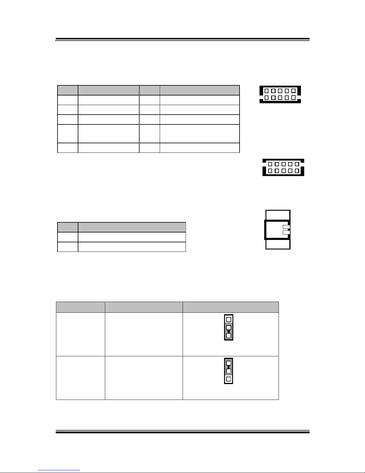
Option3
DRW1
DRW2
eSATA
/USB
2nd Display
Power
DC IN
COM(4)
LAN
VGA
USB
1
2
3
COM3
COM2
(Cash Drawer Port,
from printer board)
DRW1
DRW1-1 DRW1-2
extend with
Y cable
PA-6225 Series User Manual
PA-6822 Series User Manual
Page 62

Chapter 2 System Configuration
6
5
4
3
2
1
6
5
4
3
2
1
6
5
4
3
2
1
JP37
GPIO1
GPIO2
DRW1
DRW1-1
(Connect
wit
h
Y-cable)
DRW1-2
.
JP37: DRW1-2 control connector
SELECTION JUMPER SETTING JUMPER ILLUSTRATION
DRW1-2
Open
1-2
1
3
JP37
GND 2-3
1
3
JP37
Note: Manufacturing Default is GND.
PA-6822 Series User Manual
Page 63

Chapter 2 System Configuration
DRW1
DRW1-2
DRW1-1
DRW1, DRW1-1, DRW1-2: Signal from M/B GPIO (rear I/O)
PIN ASSIGNMENT PIN ASSIGNMENT
1
GND
4 +12V/+24V (Max. current: 1A)
2 Drawer Open 5 NC
3 Drawer Sense 6 GND
16
DRW1/
DRW1-1/
DRW1-2
DRW1-2 OPEN CLOSE
PB-6822RA,RB
Write To Write To
N/A N/A N/A N/A
PB-6822RC
Write To Write To
04h
SIO LDN
06h's 90h
00h
SIO LDN
06h's 90h
DRW1-1
OPEN CLOSE
PB-6822RA,RB
Write To Write To
700h 588h 000h 588h
PB-6822RC
Write To Write To
02h
SIO LDN
06h's 90h
00h
SIO LDN
06h's 90h
PA-6822 Series User Manual
Page 64

Chapter 2 System Configuration
1
6
DRW2
PIN ASSIGNMENT PIN ASSIGNMENT
1
GND
4 +24V
2 Drawer Open 5 NC
3 Drawer Sense 6 GND
Control Codes Hexadecimal Codes Function
<DLE EOT> 10 04 Real-time status
transmission
<DLE DC4> 10 14 Real-time output of
specified pulse
PA-6822 Series User Manual
Page 65

Page 66
SOFTWARE
This chapter provides the detailed information of driver utilities and
BIOS settings for the system.
Sections included:
Version List
OS API
Embedded Peripheral Device Firmware Control Command
- Printer
- VFD
- MSR
BIOS Operation
- Setup
- Watchdog Timer Configuration
- Update Procedure
- System Resource Map
CHAPTER
3

Chapter 3 Software
PA-6822 SERIES USER MANUAL
Page 67
3-1. Version List
Category
Item
Version
Release
Date
Image Name
System
Android
4.4.4
2015/9/22
For AR Touch Panel
I73-6822-000-01150922
For P-Cap Touch Panel
I73-6822-000-02150922
Platform
Kernal
3.10.20
2015/9/22
Android
bundled
AP
Browser
4.4.4
2015/9/22
Calculator
4.4.4
2015/9/22
Calendar
4.4.4
2015/9/22
Clock
4.4.4
2015/9/22
Downloads
4.4.4
2015/9/22
Email
4.4.4
2015/9/22
Gallery
4.4.4
2015/9/22
Movie Studio
4.4.4
2015/9/22
Music
4.4.4
2015/9/22
People
4.4.4
2015/9/22
Search
4.4.4
2015/9/22
Settings
4.4.4
2015/9/22
Added
AP
eGalaxClibrator
2.5.5120
2015/9/22
OI File
Manager
2.0.2
2015/9/22
Updated
AP
Recovery
2015/9/22
PA-6822 Utility
1.0
2015/9/22
OS API
MainActivity
A01-6822000-01150930
2015/9/30
Note: Cut off the power for mandatory shutdown but if you perform that constantly, it
may bring about system damage. All the software utilities installed in the system are
provided for free. Protech Systems won’t take responsibility for any loss or damage
caused.

Chapter 3 Software
PA-6822 SERIES USER MANUAL
Page 68
3-2. OS API
API Package Content
Operation
System
Android Framework
Directory
Contents / File Name
Description
Document\
API User Guide
A01-6822-000-01-150930.pdf
User Guide
MB-1030_Command Manual
Printer Command Manual.
MB-4103_Spec_v1.0_121109
VFD Product Specification
Function DLL
Directory
Function
File Name
Description
Library\
Cash
Drawer
CashDrawer.jar
Cash Drawer Control jar
library
VFD
VFD.jar
VFD Control jar library
MSR
MSR.jar
MSR jar libary
Printer
ThermalPrinter.jar
Printer library
SerialPort
SerialPort.jar
SerialPort library
SAPI
SAPI.jar
Communication library
Library\x86
IO
libgpio_control.so
IO Control JNI
Serial
libserial_port.so
Serial Control JNI
Sample Program
Directory
Contents / File Name
Description
DemoProject\
PA-6822Utility
Cash Drawer
VFD Function Demo Utility
MSR Function Demo
Printer Function Demo

Chapter 3 Software
PA-6822 SERIES USER MANUAL
Page 69
Programming Guide
1. Create a new project in Eclipse.
2. Copy provided JAR file (CashDrawer.jar SAPI.jar VFD.jar) into following path:
libs
- CashDrawer.jar
- VFD.jar
- SAPI.jar
- Msr.jar
- ThermalPrinter.jar
3. In Libraries tab of the target project's properties, confirm that the JAR file you
added (
If it has not been added, add the JAR file into build path using [Add Jars...].
4. Copy the library file (libeposprint.so) into following path:
Libs
-x86
|_libgpio_control.so
|_libserial_port.so
Import Function Declare:
import android.VFD.VFD;
import android.VFD.Msr;
import android.CashDrawer.CashDrawer;
import android.ThermalPrinter.ThermalPrinter;
Chapter 3 Software
PA-6822 SERIES USER MANUAL
Page 70
API Reference
-Cash Drawer API
OpenCashDrawer
Public Boolean OpenCashDrawer();
Purpose
Open the cash drawer API.
Return
True (1) on success, False (0) on failure
Example
boolean ControlResult = false;
ControlResult = CDrawer.OpenCashDrawer();
if(ControlResult)
//"Cash Drawer Control Success!"
else
//"Cash Drawer Control Failure!"
GetCashDrawerStatus
Public Boolean GetCashDrawerStatus ();
Purpose
Get the cash drawer status.
Value
Put value to Function, than get Cash drawer Status back.
Return
True (1) on success, False (0) on failure False (0)
Example
boolean ControlResult = false;
CashDrawer CDrawer =new CashDrawer( );
ControlResult = CDrawer.GetCashDrawerStatus();
if(ControlResult)
//"Cash Drawer Status Open !"
else
//"Cash Drawer Status Close !"

Chapter 3 Software
PA-6822 SERIES USER MANUAL
Page 71
-VFD API
OpenVFD
Public Boolean OpenVFD (int BuadRate)
Purpose
Open the VFD Port.
Value
Set VFD Baud Rate; MB-4103 default baud rate is 9600;
Return
True (1) on success, False (0) on failure
CloseVFD
Public Boolean CloseVFD( );
Purpose
Close the VFD Port.
Return
True (1) on success, False (0) on failure False (0)
SendCommand
Public Boolean SendCommand (byte[] data );
Purpose
Send Command to VFD.
Value
VFD Command Code. ESC/POS Command.
Return
True (1) on success, False (0) on failure False (0)
Example
VFD – Clear VFD Command (EPSON Command)
//Initialize a VFD class instance
VFD VFD_Control = new VFD();
VFD_Control. OpenVFD(9600);
byte[] data = new byte[1];
data[0] = 0x0C;
VFD_Control.SendCommand(data);
VFD_Control. CloseVFD();

Chapter 3 Software
PA-6822 SERIES USER MANUAL
Page 72
-MSR API
OpenMSR
Public Boolean OpenMSR (int BaudRate)
Purpose
Open the MSR Port.
Value
Set Msr Baud Rate; MJR243R baud rate default is 19200;
Return
True (1) on success, False (0) on failure
CloseMSR
Public Boolean CloseMSR( );
Purpose
Close the MSR Port.
Return
True (1) on success, False (0) on failure False (0)
SendCommand
Public Boolean SendCommand (byte[] data );
Purpose
Send Command to MSR.
Value
Msr Command Code.
Return
True (1) on success, False (0) on failure False (0)
Example
Msr – Send Command to Msr
//Initialize a VFD class instance
Msr Msrcontrol = new Msr ();
Msrcontrol. OpenMSR(19200);
byte[] data = new byte[1];
data[0] = 0x0C;
Msrcontrol.SendCommand(data);

Chapter 3 Software
PA-6822 SERIES USER MANUAL
Page 73
Receiver Data - Attach
Public Boolean Attach();
Purpose
Receive Msr Data
Return
True (1) on success, False (0) on failure False (0)
Example
Receive Data from MSR.
Before use this function need to implements Observer Interface.
Observer = Current class.
public class MsrActivity extends Activity implements
android.Msr.Observer {
EditText mReception;
Msr Msrcontrol ;
@Override
protected void onCreate(Bundle savedInstanceState) {
super.onCreate(savedInstanceState);
setContentView(R.layout.activity_msr);
mReception = (EditText) findViewById(R.id.EditTextReception);
Msrcontrol = new Msr();
Msrcontrol.OpenMSR(115200); Msrcontrol.Attach(this);
@Override
public void Update(final byte[] buffer, final int size)
{runOnUiThread(new Runnable() {
public void run() {
if (mReception != null) {
mReception.append(new String(buffer, 0, size));
}
}
});
}
}

Chapter 3 Software
PA-6822 SERIES USER MANUAL
Page 74
When Close:
Msrcontrol.CloseMSR(); Msrcontrol.Detach(this);
Receiver Data - Detach
Public Boolean Detach();
Purpose
Cancel Obsver from Msr Data
Return
True (1) on success, False (0) on failure False (0)
Update Event
Public Void Update(final byte[] buffer, final int size);
Purpose
Get Msr Data String
Return
byte[] buffer = Msr data
int size = buffer count.
Before use this function need to implements Observer Interface.
Observer = Current class.
Example:
@Override
public void Update(final byte[] buffer, final int size)
{runOnUiThread(new Runnable() {
public void run() {
if (mReception != null) {
String MsrString = new String(buffer, 0, size));
}
}
}

Chapter 3 Software
PA-6822 SERIES USER MANUAL
Page 75
-Thermal Printer API
OpenPrinter
Public Boolean OpenPrinter (int Baudrate)
Purpose
Open the Thermal Printer Port.
Value
Set Printer Baud Rate; MB-1030 baud rate default is 115200;
Return
True (1) on success, False (0) on failure
ClosePrinter
Public Boolean ClosePrinter( );
Purpose
Close the Thermal Printer Port.
Return
True (1) on success, False (0) on failure False (0)
CutPaper
Public Boolean CutPaper(int type);
Purpose
Cut paper function.
Value
Type = 1 (Full cut) 2(Partial cut)
Return
True (1) on success, False (0) on failure False (0)

Chapter 3 Software
PA-6822 SERIES USER MANUAL
Page 76
Text
Public Boolean Text(String data);
Purpose
Print string data to print.
Value
Data = String data.
Return
True (1) on success, False (0) on failure False (0)
Example
ThermalPrinter Printer_Control = new ThermalPrinter();
Printer_Control. OpenPrinter(115200);
Printer_Control.Text (“123456789”);
Printer_Control.Text (“\n”);
Printer_Control. ClosePrinter();
//P.S If application want to line break. Please use “\n” to change line.

Chapter 3 Software
PA-6822 SERIES USER MANUAL
Page 77
BarcodePrint
Public Boolean BarcodePrint(String Data,int Type,int Hri,int Width,int Height);
Purpose
Print Barcode.
Value
Data = Send barcode string data to printer.
Type = 1 UPC-A(1)
Type = 2 UPC-E(1)
Type = 3 EAN-13(1)
Type = 4 EAN-8(1)
Type = 5 CODE39(1)
Type = 6 ITF(1)
Type = 7 CODEBAR(1)
Type = 8 UPC-A(2)
Type = 9 UPC-E(2)
Type = 10 EAN-13(2)
Type = 11 EAN-8(2)
Type = 12 CODE39(2)
Type = 13 ITF(2)
Type = 14 CODABAR(2)
Type = 15 CODE93(2)
Type = 16 Code128(2)
Hri =
hri
Printing Position
0
No print
1
Above bar code
2
Below bar code
3,
Above and below bar code(both)
Width = 1 ≤ n ≤ 6
Height = 1 ≤ n ≤ 255
Return
True (1) on success, False (0) on failure False (0)

Chapter 3 Software
PA-6822 SERIES USER MANUAL
Page 78
LoadPicPrinter
Public Bitmap LoadPicPrinter(Bitmap data, boolean Halftone);
Purpose
Prepare to load pic sent to printer.
Value
Bitmap data (picture data)
Halftone = true or false (Enable or Disable)
Return
Return Threshold Pic.
ImagePrinter
Public Boolean ImagePrint (Bitmap data);
Purpose
Sent bitmap to printer.
Value
Bitmap data (Threshold data)
Return
True (1) on success, False (0) on failure False (0)
UploadLogo
Public Boolean UploadLogo (Bitmap data);
Purpose
Prepare to load logo sent to printer.
Value
Bitmap data (picture data)
Return
True (1) on success, False (0) on failure False (0)

Chapter 3 Software
PA-6822 SERIES USER MANUAL
Page 79
PrinterLogo
Public Void PrinterLogo();
Purpose
Printer Logo Fucntion.
SendCommand
Public Boolean SendCommand (byte[] data );
Purpose
Send command byte to printer.
Value
Command Code. Please refer MP-1030 Command Manual
Return
True (1) on success, False (0) on failure False (0)
Example
ThermalPrinter Printer_Control = new ThermalPrinter();
Printer_Control. OpenPrinter(115200);
byte[] data = new byte[2];
data[0] = 0x1B;
data[1] = 0x6d; //Partial cut
Printer_Control.SendCommand(data);
Printer_Control. ClosePrinter();

Chapter 3 Software
PA-6822 SERIES USER MANUAL
Page 80
GetRealTimeStatus
Public int GetRealTimeStatus(int n );
Purpose
Get Real Time Status.
Value
Command Code. Please refer MP-1030 Command Manual
Return
Real Time Status Byte.
Example
Int RealTimeStatus = 0 ;
ThermalPrinter Printer_Control = new ThermalPrinter();
Printer_Control. OpenPrinter(115200);
RealTimeStatus = Printer_Control.GetRealTimeStatus(2);
// TODO Detect Status
Printer_Control. ClosePrinter();

Chapter 3 Software
PA-6822 SERIES USER MANUAL
Page 81
GetPaperEndEvent
Public int GetPaperEndEvent();
Purpose
Get Paper End Status.
Return
0x00 = Response Error 0x01 = Paper End, 0x02 = Paper Normal
Int PaperEndStatus= 0 ;
ThermalPrinter Printer_Control = new ThermalPrinter();
Printer_Control. OpenPrinter(115200);
PaperEndStatus = Printer_Control.GetCoverEvent ( );
// TODO Detect Status
if (PaperEndStatus == 1)
{ Toast.makeText(PrinterActivity.this, "Paper
End!", Toast.LENGTH_SHORT).show();
}
else
{ Toast.makeText(PrinterActivity.this, "Paper
Normal", Toast.LENGTH_SHORT).show();
}
Printer_Control. ClosePrinter();

Chapter 3 Software
PA-6822 SERIES USER MANUAL
Page 82
GetCoverEvent
Public int GetCoverEvent();
Purpose
Get Cover Status.
Return
0x00 = Response Error 0x01 = Cover Open , 0x02 = Over Close
Int CoverStatus = 0 ;
ThermalPrinter Printer_Control = new ThermalPrinter();
Printer_Control. OpenPrinter(115200);
CoverStatus = Printer_Control.GetCoverEvent ( );
// TODO Detect Status
if (CoverStatus == 1)
{ Toast.makeText(PrinterActivity.this, "Cover
Open!", Toast.LENGTH_SHORT).show();
}
else
{ Toast.makeText(PrinterActivity.this, "Cover
Close!", Toast.LENGTH_SHORT).show();
}
Printer_Control. ClosePrinter();

Chapter 3 Software
PA-6822 SERIES USER MANUAL
Page 83
Receiver Data - Attach
Public Boolean Attach();
Purpose
Receive Printer Data
Return
True (1) on success, False (0) on failure False (0)
Example
Receive Data from Printer.
Before use this function need to implements Observer Interface.
Observer = Current class.
public class PrinterActivity extends Activity implements
android.ThermalPrinter.Observer {
ThermalPrinter Printer_Control;
@Override
protected void onCreate(Bundle savedInstanceState) {
super.onCreate(savedInstanceState);
setContentView(R.layout.activity_msr);
Printer_Control= new ThermalPrinter ();
Printer_Control.Attach(this);
If( !Printer_Control.OpenPrinter(115200))
{
//Port alrady open.
}
@Override
public void Update(final int Device, final int value)
{runOnUiThread(new Runnable() {
public void run() {
//Cover
if(Device == 0x01)
{
if(Value==0x01)
{
//"Cover Open"
}
else
{
//"Cover Close"
}
}
else if (Device == 0x02)
{
//Paper
if(Value==0x01)

Chapter 3 Software
PA-6822 SERIES USER MANUAL
Page 84
{
//"No Paper Present"
}
else
{
//"Paper Present"
}
}
});
}
}
When Close:
Printer_Control.ClosePrinter ();Printer_Control.Detach(this);
Receiver Data - Detach
Public Boolean Detach();
Purpose
Cancel Obsver from Msr Data
Return
True (1) on success, False (0) on failure False (0)
Update Event
Public Void Update(final int Device, final int Value);
Purpose
Get Cover & Paper event
Return
Device
0x01(Cover)
0x02 (Paper)
Value
0x01(CoverOpen)
0x01(No Paper Present)
0x02(CoverClose)
0x02(Paper Present)

Chapter 3 Software
PA-6822 SERIES USER MANUAL
Page 85
GetFWVersion
Public String GetFWVsion();
Purpose
Get FW Version
Return
FW Version String.
GetCodePageVersion
Public String GetCodePageVersion();
Purpose
Get Code Page Version
Return
Code Page Version String.

Chapter 3 Software
PA-6822 SERIES USER MANUAL
Page 86
-Serial Port API
OpenSerialPort
Public Boolean OpenSerialPort (
String PortName,
int BaudRate,
int Parity,
int Databit,
int Stopbit
boolean enRTS)
Purpose
Open the SerialPort Port.
Value
PortName = /dev/ttyHS0 or other port.
BaudRate = Example 9600 or 115200
Parity = None = 0 , Odd = 1 ,Even = 2
Databit = 5 ,6,7, 8
Stopbit = None = 0 , One = 1 ,Two = 2
EnRTS = Flow Control
True = Enable
False = Disable
Return
True (1) on success, False (0) on failure
CloseSerialPort
Public Boolean CloseSerialPort( );
Purpose
Close the SerialPort Port.
Return
True (1) on success, False (0) on failure False (0)

Chapter 3 Software
PA-6822 SERIES USER MANUAL
Page 87
SendCommand
Public Boolean SendCommand (byte[] data );
Purpose
Send Command to SerialPort.
Value
Byte array data.
Return
True (1) on success, False (0) on failure False (0)
Example
SerialPort– Send Command to SerialPort
//Initialize a VFD class instance
SP SerialPortcontrol = new SP();
SerialPortcontrol.OpenSerialPort(19200);
byte[] data = new byte[1];
data[0] = 0x0C;
SerialPortcontrol.SendCommand(data);

Chapter 3 Software
PA-6822 SERIES USER MANUAL
Page 88
Receiver Data - Attach
Public Boolean Attach();
Purpose
When class need to receiver serial port data need to use.
Return
True (1) on success, False (0) on failure False (0)
Example
Receive Data from serial port.
Before use this function need to implements Observer Interface.
Observer = Current class.
SP SerialPortcontrol = new SP();
SerialPortcontrol.OpenSerialPort(19200); SerialPortcontrol.Attach(this);
@Override
public void Update(final byte[] buffer, final int size)
{runOnUiThread(new Runnable() {
public void run() {
if (mReception != null) {
mReception.append(new String(buffer, 0, size));
When Close:
SerialPortcontrol.CloseSerialPort();SerialPortcontrol.Detach(this);
Receiver Data - Detach
Public Boolean Detach();
Purpose
Cancel Obsver from SerialPort Data
Return
True (1) on success, False (0) on failure False (0)

Chapter 3 Software
PA-6822 SERIES USER MANUAL
Page 89
Update Event
Public Void Update(final byte[] buffer, final int size);
Purpose
Get Serial Port Data String
Return
byte[] buffer = Serial Port data
int size = buffer count.
Before use this function need to implements Observer Interface.
Observer = Current class.
Example:
@Override
public void Update(final byte[] buffer, final int size)
{runOnUiThread(new Runnable() {
public void run() {
if (mReception != null) {
String SerialPortRev= new String(buffer, 0, size));
}
}
}

Chapter 3 Software
PA-6822 SERIES USER MANUAL
Page 90
Command lists and driver installation guide for embedded peripheral devices of the
system - printer board, VFD and MSR – are explicitly included in this section.
3-3. EMBEDDED PERIPHERAL DEVICES
Command lists and driver installation guide for embedded peripheral devices of the
system - printer board, VFD and MSR – are explicitly included in this section.
3-3-1. Printer Board: MB-1030
3-3-1-1. Command List
1. Printer Registry Operation
Registry Name
Default Data
Notes
BaudRate
115200
-
BitLength
8 - Parity
N - Stop
1
-

Chapter 3 Software
2. Command List
Standard commands
Command
RA RB
Command
RA RB
Command
RA RB
HT
V
ESC D V
GS / V V
LF V V
ESC E V V
GS :
FF
V
ESC G V
GS B V V
CR V V
ESC J V V
GS H V V
CAN
V
ESC L V
GS I V V
DLE EOT V V
ESC M V V
GS L V V
DLE ENQ
V
ESC c 4 V
GS P V V
DLE DC4 V V
ESC c 5 V
GS V V V
ESC FF
V
ESC d V V
GS W V
ESC SP V V
ESC p V V
GS \
ESC ! V V
ESC t V V
GS ^
ESC $ V V
ESC { V V
GS a V V
ESC %
FS g 1
GS b
ESC &
FS g 2
GS f V V
ESC *
V
FS p V V
GS h V V
ESC - V V
FS q V V
GS k V V
ESC 2 V V
GS ! V V
GS r V V
ESC 3 V V
GS $ V
GS v 0 V V
ESC = V V
GS * V V
GS w V V
ESC ?
GS ( A V V
ESC @ V V
GS ( K V
Kanji Control Commands Other Commands
Command MB-1030 RA MB-1030 RB
Command MB-1030 RA MB-1030 RB
FS !
V V
ESC i
V V
FS &
V V
ESC m
V V
FS -
V
DC2 ;
V
FS .
V V
GS p 1
V
FS 2
FS C
FS S
V
FS W
V
PA-6822 Series User Manual
Page

Chapter 3 Software
COMMAND LIST
Standard Commands
Control
Codes
Hexadec
-imal
Codes
Function
Stand
-ard
Mode
Page
Mode
<HT> 09 Horizontal tab V V
<LF> 0A Print and line feed V V
<FF> 0C
Print and recover to standard mode
(in page mode)
Ignored V
<CR> 0D Print and carriage return V V
<CAN> 18 Cancel print data in page mode Ignored V
<DLE EOT>
10 04 Real-time status transmission V V
<DLE ENQ>
10 05 Real-time request to printer V V
<DLE DC4>
10 14 Real-time output of specified pulse V V
<ESC FF>
1B 0C Print data in page mode Ignored V
<ESC SP>
1B 20 Set right-side character spacing V V
<ESC !>
1B 21 Select print mode(s) V V
<ESC $>
1B 24 Set absolute print position. V V
<ESC *>
1B 2A Select bit image mode V V
<ESC -> 1B 2D Turn underline mode on/off. V V
<ESC 2> 1B 32 Select default line spacing V V
<ESC 3> 1B 33 Set line spacing V V
<ESC => 1B 3D Select peripheral device V V
<ESC @> 1B 40 Initialize printer V V
<ESC D> 1B 44 Set horizontal tab position V V
<ESC E> 1B 45 Turn emphasized mode on/off V V
<ESC G> 1B 47 Turn double-strike mode on/off V V
<ESC J> 1B 4A Print and feed paper V V
<ESC L> 1B 4C Select page mode
◎
Ignored
<ESC M > 1B 4D Select character font V V
<ESC R> 1B 52 Select an international character set V V
<ESC S> 1B 53 Select standard mode Ignored V
<ESC T> 1B 54 Select print direction in page mode ▲ V
<ESC V> 1B 56
Turn 90 degree clockwise rotation
mode on/off
V ▲
<ESC W> 1B 57 Set printing area in page mode ▲ V
<ESC \> 1B 5C Set relative print position V V
<ESC a> 1B 61 Select justification
◎
▲
<ESC c 3> 1B 63 33
Select paper sensor(s) to output paper-end
signals
V V
<ESC c 4> 1B 63 34 Select paper sensor(s) to stop printing V V
<ESC c 5> 1B 63 35 Enable/disable panel buttons V V
<ESC d> 1B 64 Print and feed n lines V V
<ESC i> 1B 69 Full cut V Disabled
<ESC m> 1B 6D Partial cut V Disabled
<ESC p> 1B 70 General pulse V V
<ESC t> 1B 74 Select character code table V V
PA-6822 Series User Manual
Page

Chapter 3 Software
′
<ESC {>
1B 7B Turn upside-down printing mode on/off
◎
▲
<FS p> 1C 70 Print NV bit image V Disabled
<FS q> 1C 71 Define NV bit image
◎
Disabled
<GS !> 1D 21 Select character size V
<GS $> 1D 24
Set absolute vertical print position in
page mode
Ignored V
<GS *> 1D 2A Define download bit images V V
<GS ( A> 1D 28 41 Execute test print V Disabled
<GS ( K> 1D 28 4B Set print density V Disabled
<GS /> 1D 2F Print download bit image ● V
<GS B>
1D 42
Turn white/black reverse printing mode
on/off
V V
<GS H>
1D 48 Select printing position of HRI characters V V
<GS I> 1D 49 Transmit printer ID V Disabled
<GS L> 1D 4C Set left margin
◎
Disabled
<GS P>
1D 50 Set basic calculated pitch V V
<GS V>
1D 56 Cut paper
◎
V
<GS W>
1D 57 Set printing area width
◎
▲
<GS \> 1D 5C
Set relative vertical print position in
page mode
Ignored
<GS a> 1D 61
Enable/disable Automatic Status Back
(ASB)
V V
<GS f> 1D 66 Select font for HRI characters V V
<GS h> 1D 68 Set bar code height V V
<GS k> 1D 6B Print bar code ● V
<GS r> 1D 72 Transmit status V V
<GS v 0> 1D 76 30 Print raster bit image ● Disabled
<GS w>
1D 77 Set bar code width V V
Two-dimensional Bar Code Commands
Control
Codes
Hexadec
-imal
Codes
Function
Stand
-ard
Mode
Page
Mode
<DC2 ;> 12 3B Specifies a module size of QR Code and
Data Matrix
V
V
<GS p 1> 1D 70 01 Prints QRCode data based on the specified
contents
V
V
PA-6822 Series User Manual
Page

Chapter 3 Software
Kanji Control Commands
(when the Japanese, Simplified Chinese, Traditional Chinese, or Korean model
is used)
Control
Codes
Hexadec
-imal
Codes
Function
Stand
-ard
Mode
Page
Mode
<FS !> 1C 21 Set print mode(s) for Kanji characters V
V
<FS &> 1C 26 Select Kanji character mode V
V
<FS -> 1C 2D
Turn underline mode on/off for Kanji
characters
V V
<FS .> 1C 2E Cancel Kanji character mode V
V
<FS S> 1C 53 Set Kanji character spacing V
V
<FS W> 1C 57
Turn quadruple-size mode on/off for Kanji
characters
V V
Command classification
Executing : Printer executes the command, which does not then affect the following data.
Setting : Printer uses flags to make settings, and those settings affect the following data.
○: Enabled.
◎
: Enabled only when the command is set at the beginning of a line.
●: Enabled only when data is not present in the printer buffer.
▲: Only value setting is possible.
Disabled: Parameters are processed as printable data.
Ignored: All command codes including parameters are ignored and nothing is executed.
COMMAND DETAILS
STANDARD COMMAND DETAILS
HT
[Name] Horizontal tab
[Format]
ASCII HT
Hex. 09
Decimal 9
[Range] N/A
[Description]
Moves print position to next horizontal tab position.
This command is ignored if the next tab is not set.
If the next tab position exceeds the print region, the print position is moved
to [print region + 1].
The horizontal tab position is set by ESC D (Set/cancel horizontal tab
position).
When the print position is at the [print region + 1] position and this
command is received, the current line buffer full is printed and a horizontal
tab is executed from the top of the next line.
The initial value of the horizontal tab position is every 8 characters of Font
A (the 9th, 17th, 25
th
positions, etc.)
PA-6822 Series User Manual
Page

Chapter 3 Software
LF
[Name] Print and line feed
[Format]
ASCII LF
Hex. 0A
Decimal 10
[Range] N/A
[Description]
Prints the data in the print buffer and performs a line feed based on the set line
feed amount.
After execution, makes the top of the line the next print starting position.
FF
[Name] Print and recover to standard mode (in page mode)
[Format]
ASCII FF
Hex. 0C
Decimal 12
[Range] N/A
[Description]
Prints all buffered data to the print region c
ollectively, then recovers to the standard
mode.
All buffer data is deleted after printing.
The print area set by ESC W (Set print region in page mode) is reset to the
default setting.
No paper cut is executed.
Sets the print position to the beginning of the next line after execution.
This command is enabled only in page mode.
CR
[Name] Print and carriage return
[Format]
ASCII CR
Hex. 0D
Decimal 13
[Range] N/A
[Description]
When an automatic line feed is enabled, this command functions in the same
way as LF(print and line feed). When the automatic line feed is disabled, this
command is ignored.
This command is ignored with serial interface models.
Sets the print position to the beginning of the next line after execution.
CAN
[Name] Cancel print data in page mode
[Format]
ASCII CAN
Hex. 18
Decimal 24
[Range] N/A
[Description]
Deletes all print data in the currently set print region in page mode.
This command is enabled only in page mode.
Portions included in the currently set print region are also deleted, even if
previously set print region data.
PA-6822 Series User Manual
Page

Chapter 3 Software
DLE EOT n
[Name] Real-time status transmission.
[Format]
ASCII OLE EOT n
Hex. 10 04 n
Decimal 16 4 n
[Range] 1 ≤ n ≤ 4
[Description]
Transmits the selected printer status specified by n in real time, according to the
following parameters:
n = 1 : Transmit printer status. n = 2 : Transmit off-line status.
n = 3 : Transmit error status. n = 4 : Transmit paper roll sensor status.
n = 1 : Printer status.
Bit On / Off
Hex Decimal
Function
0 Off 00 0 Not used. Fixed to Off.
1 On 02 2 Not used. Fixed to On.
2 Off 00 0 Drawer open/close signal is LOW.
On 04 4 Drawer open/close signal is HIGH.
3 Off 00 0 On-line.
On 08 8 Off-line.
4 On 10 16 Not used. Fixed to On.
5 Off 00 0 Not used. Fixed to Off.
6 Off 00 0 Not used. Fixed to Off.
7 Off 00 0 Not used. Fixed to Off.
n = 2 : Off-line status.
Bit On / Off
Hex Decimal
Function
0 Off 00 0 Not used. Fixed to Off.
1 On 02 2 Not used. Fixed to On.
2 Off 00 0 Cover is closed.
On 04 4 Cover is open.
3 Off 00 0 Not used. Fixed to Off.
4 On 10 16 Not used. Fixed to On.
5 Off 00 0 No paper-end stop.
On 20 32 Printing stops due to paper end.
6 Off 00 0 No error.
On 40 64 Error occurs.
7 Off 00 0 Not used. Fixed to Off.
n = 3 : Error status
Bit On / Off
Hex Decimal
Function
0 Off 00 0 Not used. Fixed to Off.
1 On 02 2 Not used. Fixed to On.
2 Off 00 0 Not used. Fixed to Off.
3 Off 00 0 Not used. Fixed to Off.
4 On 10 16 Not used. Fixed to On.
5 Off 00 0 Not used. Fixed to Off.
6 Off 00 0 Not used. Fixed to Off.
7 Off 00 0 Not used. Fixed to Off.
PA-6822 Series User Manual
Page

Chapter 3 Software
Bit On / Off
Hex Decimal
Function
0 Off 00 0 Not used. Fixed to Off.
1 Off 02 2 Not used. Fixed to On.
2 Off 00 0 No paper-near-end stop.
On 04 4
Printing stops due to paper near end.
3 Off 00 0 No paper-near-end stop.
On 08 8
Printing stops due to paper near end.
4 On 10 16 Not used. Fixed to On.
5 Off 00 0 No paper-end stop.
On 20 32 Printing stops due to paper end.
6 Off 00 0 No paper-end stop.
On 40 64 Printing stops due to paper end.
7 Off 00 0 Not used. Fixed to Off.
DLE ENQ n
[Name] Real-time request to printer.
[Format]
ASCII DLE ENQ n
Hex. 10 05 n
Decimal 16 5 n
[Range] 1 ≤ n ≤ 2
[Description]
Responds to requests n specifications from the host in real-time. n specifications
are below.
n = 1: Recover from the error and start printing from the line where the error
occurred.
n = 2: Recover from error after clearing the reception buffer and print buffer.
This command is enabled even when the printer specification is disabled by ESC
= (select
peripheral devices).
DLE DC4 n m t
[Name] Real-time output of specified pulse.
[Format]
ASCII DLE DC4 n m t
Hex. 10 14 n m t
Decimal 16 20 n m t
[Range]
n = 1
m = 0,1
1 ≤ t ≤ 8
[Description]
This outputs a signal specified by t to the connector pin specified by m.
m = 0: #2 Pin of the drawer kick connector
m = 1: #5 Pin of the drawer kick connector
On time is set to t x 100 msec; Off time is set to t x 100 msec.
PA-6822 Series User Manual
Page

Chapter 3 Software
ESC FF
[Name] Print data in page mode.
[Format]
ASCII ESC FF
Hex. 1B 0C
Decimal 27 12
[Range] N/A
[Description]
Prints all buffered data in the print area collectively in page mode.
This command is enabled only in page mode.
Holds the following information after printing.
a. Expanded data
b. Character print direction selection in page mode (ESC T)
c. Set print region (ESC W) in the page mode.
d. Character expansion position
ESC SP n
[Name] Set right-side character spacing.
[Format]
ASCII ESC SP n
Hex. 1B 20 n
Decimal 27 32 n
[Range]
0 ≤ n ≤ 255
Initial Value n = 0
[Description]
This command sets the size of space to right of character.
Right space = n × [horizontal motion units].
ESC ! n
[Name] Select print mode(s).
[Format]
ASCII ESC ! n
Hex. 1B 21 n
Decimal 27 33 n
[Range]
0 ≤ n ≤ 255
Initial Value n = 0
[Description]
This command selects print mode(s) with bits having following meanings.
Bit On / Off
Hex Deci
mal Function
0 Off 00 0 Character font A selected.
On 01 1 Character font B selected.
1 Off 00 0 Not used. Fixed to Off.
2 Off 00 0 Not used. Fixed to Off.
3 Off 00 0 Emphasized mode not selected.
On 08 8 Emphasized mode selected.
4 Off 00 0 Double-height mode not selected
On 10 16 Double-height mode selected
5 Off 00 0 Double-width mode not selected.
On 20 32 Double-width mode selected.
6 Off 00 0 Not used. Fixed to Off.
7 Off 00 0 Underline mode not selected.
On 80 128 Underline mode selected.
PA-6822 Series User Manual
Page

Chapter 3 Software
ESC $ nL nH
[Name] Set absolute print position.
[Format]
ASCII ESC $ nL nH
Hex. 1B 24 nL nH
Decimal 27 36 nL nH
[Range] 0 ≤ (nL + nH x 256) ≤ 65535 (0 ≤ nH ≤ 255, 0 ≤ nL ≤ 255)
[Description]
This command specifies the next print starting position in reference to the left
edge of the print area. The printing start position is calculated using
(nL + nH x 256) x (vertical or horizontal motion units). Specifications exceeding
the print range are ignored.
ESC * m nL nH d1…dk
[Name] Select bit image mode
[Format]
ASCII ESC * m nL nH d1...dk
Hex. 1B 2A m nL nH d1...dk
Decimal 27 42 m nL nH d1...dk
[Range]
m = 0,1,32,33
0 ≤ nL ≤ 255
0 ≤ nH ≤ 3
0 ≤ d ≤ 255
[Description]
Selects a bit-image mode in mode m for the number of dots specified by nL and
nH.
m = 1,33 : (nL+nH×256)<576 (3 inch);(nL+nH×256)<432 (2 inch).
m = 0,32 : (nL+nH×256)<288 (3 inch);(nL+nH×256)<216 (2 inch).
m
Mode
Number
of
Vert. Dir.
Dots
Density of
Vert. Dir.
Dots
Density of
Hor. Dir.
Dots
Data Count (k)
0
8 dot single
density
8 67 DPI 101 DPI nL+nH×256
1
8 dot double
density
8 67 DPI 203 DPI nL+nH×256
32
24 dot single
density
24 203 DPI 101 DPI
(nL+nH×256)
×3
33
24 dot
double
density
24 203 DPI 203 DPI
(nL+nH×256)
×3
ESC - n
[Name] Turn underline mode on/off.
[Format]
ASCII ESC - n
Hex. 1B 2D n
Decimal 27 45 n
[Range]
0 ≤ n ≤ 2
Initial Value n = 0
[Description]
This command enables the print data following it to be printer out underlined.
The underline mode varied depending on the following values of n:
n Function
0 Turns off underline mode
1 Turns on underline mode, set at 1-dot thick
2 Turns on underline mode, set at 2-dot thick
PA-6822 Series User Manual
Page
 Loading...