


USER’S
MANUAL
PA-3122
10.4” POS Terminal
Powered by Intel® Celeron®
J1900 Quad-Core
PA-3122
M1

PA-3122 POS System
With SATA/mSATA/3COM/4USB
COPYRIGHT NOTICE & TRADEMARK
All trademarks and registered trademarks mentioned herein are the property of their
respective owners.
This manual is copyrighted June 2014. You may not reproduce or transmit in any
form or by any means, electronic, or mechanical, including photocopying and
recording.
DISCLAIMER
This user’s manual is meant to assist users in installing and setting up the system. The
information contained in this document is subject to change without any notice.
CE NOTICE
This is a class A product. In a domestic environment this product may cause radio
interference in which case the user may be required to take adequate measures.

FCC NOTICE
This equipment has been tested and found to comply with the limits for a Class A
digital device, pursuant to part 15 of the FCC Rules. These limits are designed to
provide reasonable protection against harmful interference when the equipment is
operated in a commercial environment. This equipment generates, uses, and can
radiate radio frequency energy and, if not installed and used in accordance with the
instruction manual, may cause harmful interference to radio communications.
Operation of this equipment in a residential area is likely to cause harmful interference
in which case the user will be required to correct the interference at his own expense.
You are cautioned that any change or modifications to the equipment not expressly
approve by the party responsible for compliance could void your authority to operate
such equipment.
CAUTION! Danger of explosion if battery is incorrectly replaced. Replace only with the
same or equivalent type recommended by the manufacturer. Dispose of used batteries
according to the manufacturer’s instructions.
WARNING! Some internal parts of the system may have high electrical voltage. And
therefore we strongly recommend that qualified engineers can open and disassemble the
system.The LCD and Touchscreen are easily breakable, please handle them with extra
care.

Contents
TABLE OF CONTENTS
CHAPTER 1 INTRODUCTION
1-1 About This Manual…................................................................... 1-2
1-2 POS System Illustration…............................................................ 1-3
1-3 System Specifications................................................................... 1-4
1-4 Safety Precautions….................................................................... 1-6
CHAPTER 2 SYSTEM CONFIGURATION
2-1 System External I/O Port & Pin Assignment.…........................... 2-2
2-2 Main Board Component Locations & Jumper Settings…………. 2-7
2-3 Printer Board Component Locations & Pin Assignment.............. 2-26
2-4 VFD Board Component Locations & Pin Assignment................. 2-44
2-5 MSR Board Component Locations & Pin Assignment................. 2-46
CHAPTER 3 SOFTWARE
3-1 Driver……..….............................................................................. 3-2
3-2 Embedded Peripheral Devices……….......................................... 3-8
3-3 API………………………………................................................ 3-43
3-4 BIOS Operation….……............................................................... 3-56
3-5 Watchdog Timer Configuration………………………………… 3-100
3-6 BIOS Update Instructions………………………………………. 3-103
3-7 System Resource Map…………………………………………... 3-107
CHAPTER 4 SYSTEM DIAGRAMS
Exploded Diagram for System Top Case...…………………………….. 4-2
Exploded Diagram for System LCD Panel….………………………...... 4-9
Exploded Diagram for System Bottom Case…………………................ 4-13
Exploded Diagram for Printer……..……………………….................... 4-19
Exploded Diagram for MSR……………..……………………………... 4-25
Exploded Diagram for VFD………………………................................. 4-26
Exploded Diagram for HDD………………………................................ 4-28

Page:1-1
INTRODUCTION
This chapter gives you the information for the PA-3122. It also outlines
the system specifications.
Sections included:
About This Manual
POS System Illustration
System Specifications
Safety precautions
Experienced users can jump to chapter 2 on page 2-1
for a quick start.
CHAPTER
1

Chapter 1 Introduction
PA-3122 SERIES USER′S MANUAL
Page: 1-2
1-1. ABOUT THIS MANUAL
Thank you for purchasing our PA-3122 Series System. The PA-3122 is an updated
system designed to be comparable with the highest performance of IBM AT personal
computers. The PA-3122 provides faster processing speed, greater expandability and
can handle more tasks than before. This manual is designed to assist you how to install
and set up the whole system. It contains four chapters and two appendixes. Users can
configure the system according to their own needs.
Chapter 1 Introduction
This chapter introduces you to the background of this manual. It also includes
illustrations and specifications for the whole system. The final section of this chapter
indicates some safety reminders on how to take care of your system.
Chapter 2 System Configuration
This chapter outlines the location of motherboard, printer, VFD, MSR components
and their function. You will learn how to set the jumpers and configure the system to
meet your own needs.
Chapter 3 Software
This chapter contains detailed information for driver installations of the Intel® Utility,
VG, LAN, Sound, Touch Screen, embedded peripheral devices, BIOS setup & update,
Watchdog timer and resource map.
Chapter 4 System Diagrams
This chapter shows the exploded diagrams and part numbers of PA-3122 components.
Appendix A System Display
The appendix illustrates the installation of 2nd display and setting of the system display.

Chapter 1 Introduction
PA-3122 SERIES USER′S MANUAL
Page: 1-3
1-2. POS SYSTEM ILLUSTRATION
Top View Bottom View
M4 * 4
100
100
Front View Rear View
286.074
147.098
Side View
Quarter View
12.1
135
22°
Unit: mm

Chapter 1 Introduction
PA-3122 SERIES USER′S MANUAL
Page: 1-4
1-3. SYSTEM SPECIFICATIONS
System
CPU Intel® Celeron® J1900 Quad-Core 2.0GHz
Memory 1 x DDR3L SO-DIMM 204-pin socket, up to 8GB
OS Support Microsoft Windows 8 & POSReady7
Power Supply 72~120 Watt power adapter
Audio 2W speaker
BIOS AMI SPI BIOS, 8 Mbits with VGA BIOS
System Weight With power adapter approx. 4.5 kg
Dimension (W x H x D) 300mm x 299mm x 135mm
Certificate CE/FCC
Storage
SATA 1 x 2.5” HDD or SSD
mSATA 1 x SSD
I/O Ports
Serial Port 3 x DB-9 (COM2,COM3,COM4; COM1 is optional.)
5 x wafers on board:
- COM1-1: Co-lay with COM1
- COM2-1: Co-lay with COM2
- COM3-1: Co-lay with COM3
- COM4-1: Co-lay with COM4-2
USB 5 x USB2.0 (4 on rear I/O, 1 on side bezel)
Parallel Port (Optional) 1 x printer port
LAN 1 x Giga LAN
VGA 1 x DB-15 VGA Interface
Display
LCD Interface 10.4” TFT XGA
Max. Resolution
1024 x 768
800 x 600
Brightness
400 cd/m2
230 cd/m2
Signal Interface TTL (18-bit)
Viewing Angel 24~30°
Touch Panel 10.4” 5-wire analog resistive

Chapter 1 Introduction
PA-3122 SERIES USER′S MANUAL
Page: 1-5
Environment
Temperature Operating: 0~35°C (32 ~ 95°F)
Storage: -20~60°C (-4 ~ 140°F)
Humidity 20~90%
Optional accessories
Customer Display VFD kit, 20 columns & 2 lines
(Each column contains 5x7 dots.)
Printer 2” or 3” easy-loading thermal printer with auto-cutter
MSR & i-Button ISO I ,II, III; JIS I,II and support information key
RFID ISO14443A Read/Write; ISO18092 Read only
Fingerprint 8-bit grayscale reader

Chapter 1 Introduction
PA-3122 SERIES USER′S MANUAL
Page: 1-6
1-4. SAFETY PRECAUTIONS
The following messages are safety reminders on how to protect your systems from
damages, and extending the life cycle of the system.
1. Check the Line Voltage
a. The operating voltage for the power supply should be within the range of
100V to 240V AC; otherwise the system may be damaged.
2. Environmental Conditions
a. Place your PA-3122 on a sturdy, level surface. Be sure to allow enough
space around the system to have easy access needs.
b. Avoid installing your PA-3122 Series POS system in extremely hot or cold
places.
c. Avoid exposure to sunlight for a long period of time (for example, in a
closed car in summer time. Also avoid the system from any heating device.).
Or do not use the PA-3122 when it has been left outdoors in a cold winter
day.
d. Bear in mind that the operating ambient temperature is between 0°C and
35°C (32°F and 95°F).
e. Avoid moving the system rapidly from a hot place to a cold place, and vice
versa, because condensation may occur inside the system.
f. Protect your PA-3122 against strong vibrations, which may cause hard disk
failure.
g. Do not place the system too close to any radio-active device. Radio-active
device may cause signal interference.
h. Always shutdown the operation system before turning off the power.
3. Handling
a. Avoid placing heavy objects on the top of the system.
b. Do not turn the system upside down. This may cause the hard drive to
malfunction.
c. Do not allow any objects to fall into this product.
d. If water or other liquid spills into the product, unplug the power cord
immediately.

Chapter 1 Introduction
PA-3122 SERIES USER′S MANUAL
Page: 1-7
4. Good Care
a. When the outside case gets stained, remove the stains using neutral washing
agent with a dry cloth.
b. Never use strong agents such as benzene and thinner to clean the surface of
the case.
c. If heavy stains are present, moisten a cloth with diluted neutral washing
agent or alcohol and then wipe thoroughly with a dry cloth.
d. If dust is accumulated on the case surface, remove it by using a special
vacuum cleaner for computers.

Page 2-1
SYSTEM
CONFIGURATION
Helpful information that describes the jumper and connector settings,
component locations, and pin assignment.
Sections included:
External I/O Port Pin Assignment
How to Set Jumpers
Component Locations & Jumper Settings
- Mainboard
- Printer Board (peripheral device)
- VFD Board (peripheral device)
- MSR Board (peripheral device)
CHAPTER
2

Chapter 2 System Configuration
PA-3122 SERIES USER’S MANUAL
Page: 2-2
2-1. SYSTEM EXTERNAL I/O PORT & PIN ASSIGNMENT
Rear I/O
Option1Option3
Option2
DRW1 eSATA
/USB
2nd Display
Power
DC IN
COM
LAN
VGA
USB
1
2
3
COM3
COM2
Parallel Port
(LPT, D-sub 25-pin)
(Cash Drawer Port,
from printer board)
COM1 COM4
(2 x RS-232, D-sub 9-pin)
Side I/O
Power USB4
button

Chapter 2 System Configuration
PA-3122 SERIES USER’S MANUAL
Page: 2-3
2-1-1. Power Button
To turn on the system, press the power button on the side
of the system briefly.
ACTION ASSIGNMENT
Click 0V
Release +3.3V
2-1-2. DC-IN Port
DC IN: DC Power-In Port (rear IO)
PIN ASSIGNMENT PIN ASSIGNMENT
1 GND 3 +24V
2 GND 4 +24V
2-1-3. VGA Port
VGA: VGA Port, D-Sub 15-pin (rear IO)
PIN ASSIGNMENT PIN ASSIGNMENT
1 RED 9 +5V
2 GREEN 10 GND
3 BLUE 11 NC
4 NC 12 DDCA DATA
5 GND 13 HSYNC
6 GND 14 VSYNC
7 GND 15 DDCA CLK
8 GND
34
12
DC IN
Power
Button
15
610
1115
VGA

Chapter 2 System Configuration
PA-3122 SERIES USER’S MANUAL
Page: 2-4
2-1-4. COM Port
COM2, COM3, COM4: D-Sub9 Serial Ports (rear IO)
COM2: Co-lay with COM2-1
COM3: Co-lay with COM3-1
PIN ASSIGNMENT PIN ASSIGNMENT
1 DCD 6 DSR
2 RXD 7 RTS
3 TXD 8 CTS
4 DTR 9 RI/+5V/+12V
selectable (Max.
current: 1A)
5 GND
Note: COM3 & COM3-1 will not function when jumpers
JP20, JP21, JP22 are set as 2-3 connected (i-Button).
Refer to the section i-Button Function Selection for
details. COM4-2 will not function when COM4-1 is
selected as the printer control interface.
2-1-5. LAN Port
LAN: LAN RJ45 Port (rear IO)
PIN ASSIGNMENT PIN ASSIGNMENT
1 MDIP0 5 MDIP2
2 MDIN0 6 MDIN2
3 MDIP1 7 MDIP3
4 MDIN1 8 MDIN3
LAN LED Indicator:
Right Side LED
Yellow Color Blinking LAN Message Active
Off No LAN Message Active
Left Side LED
Green Color On 10/100Mbps LAN Speed Indicator
Orange Color on Giga LAN Speed Indicator
Off No LAN switch/ hub connected.
5
1
9
6
COM2/
COM3/
COM4/
81
Green Yellow
LAN

Chapter 2 System Configuration
PA-3122 SERIES USER’S MANUAL
Page: 2-5
2-1-6. Cash Drawer Port
DRW1: Signal from M/B GPIO (rear I/O)
PIN ASSIGNMENT PIN ASSIGNMENT
1
GND
4 +12V/+24V (Max. current: 1A)
2 Drawer Open 5 NC
3 Drawer Sense 6 GND
DRW1 DRW1-1 DRW1-2
Open
Write "700"h to I/O port
"588"h
Write "80000003"h to I/O
Port "588"h
Close
Write "00"h to I/O port
"588"h
Write "00"h to I/O port
"588"h
2-1-7. USB Ports
USB0, USB1, USB2, USB3, USB4: USB Type A Ports
USB0~3: Rear I/O
USB4: Side IO
PIN ASSIGNMENT PIN ASSIGNMENT
1 +5V (Max.
current: 0.5A)
3 D+
2 D- 4 GND
1 4
USB0/
USB1/
USB2/
USB4/
1 4
USB3
16
DRW1

Chapter 2 System Configuration
PA-3122 SERIES USER’S MANUAL
Page: 2-6
2-1-8. Printer Port (Optional)
LPT: Printer Port, D-Sub 25-pin, co-lay with LPT1
PIN ASSIGNMENT PIN ASSIGNMENT
1 STBJ 14 ALFJ
2 PDR0 15 ERRJ
3 PDR1 16 PARR_INITJ
4 PDR2 17 SLCTINJ
5 PDR3 18 GND
6 PDR4 19 GND
7 PDR5 20 GND
8 PDR6 21 GND
9 PDR7 22 GND
10 ACKJ 23 GND
11 BUSY 24 GND
12 PE 25 GND
13 SLCTJ
113
25 14
LPT

Chapter 2 System Configuration
PA-3122 SERIES USER’S MANUAL
Page: 2-7
2-2. MAINBOARD COMPONENT LOCATIONS & JUMPER
SETTINGS
M/B: PB-6822
LVDS1
USB7
J3
JP_VDD1
JP_12
JP_8
JP_9
USB1
JP32
SW1_3
JP19
JP30
USB2
COM1_1
COM4_1
COM2_1
COM3_1
JP_COM4
JP_COM3
JP_COM2
JP_COM1
PRT_PWR1
PWR_IN1
VGA1
USB8LAN1
LINE-OUT1
JP31
USB5
SW1
USB6
JI_BUTTON1
PS/2_2
SP1
SPK1
SLOT1
COM4_2
JP20
JP21
JP22
COM2
COM3
DC5V_PWR1
JP37
JP29
JP5
DC12V_PWR1
LPT1
J2
SATA2
SATA1
JPWR_4P2
JPWR_4P1
TOUCH3
JP14
JP15
JINVDRV1
JINV4
JP4
JP3
JP38JP39
30
291
2
Battery
1
1
1
1
1 31 4
1
6
5
10
14
1
1
1
1
1 21 21 2
5 65 65 6
526
1
1
1
1
1
112
910
6
1
1
6
1
1
15
15
1
5
1
5
1 15 17 51
2 16 18 52
1
4
1
127
8
1
10
5
6
1
6
1
1
1
2
255
6
5
6
6
1
1
4
1
2
6
10
5
10
5
26
13
14
1
1 4
1 4
1 7
1 7
Intel
®
Celeron® J1900
Quad-Core
DIMM1
1
2
71
72
73
74
203
204
ESATA1
DRW1
15
PB-6822 Mainboard Component Locations

Chapter 2 System Configuration
PA-3122 SERIES USER’S MANUAL
Page: 2-8
SLOT2
1
15
17
51
2
16
18
52
PB-6822 Mainboard Component Locations - Rear

Chapter 2 System Configuration
PA-3122 SERIES USER’S MANUAL
Page: 2-9
2-2-1. How to Set Jumpers
You can configure your board by setting the jumpers. A jumper consists of two or three
metal pins with a plastic base mounted on the card, and by using a small plastic "cap",
also known as the jumper cap (with a metal contact inside), you are able to connect the
pins. So you can set-up your hardware configuration by "opening" or "closing" pins.
Jumpers can be combined into sets that called jumper blocks. When jumpers are all in
the block, you have to put them together to set up the hardware configuration. The
figure below shows what this looks like.
Jumpers & caps
If a jumper has three pins for example, labelled PIN1, PIN2, and PIN3. You can
connect PIN1 & PIN2 to create one setting and shorting. You can either connect PIN2
& PIN3 to create another setting. The same jumper diagrams are applied all through
this manual. The figure below shows what the manual diagrams look and what they
represent.

Chapter 2 System Configuration
PA-3122 SERIES USER’S MANUAL
Page: 2-10
Jumper diagrams
Jumper settings

Chapter 2 System Configuration
PA-3122 SERIES USER’S MANUAL
Page: 2-11
2-2-2. COM Port RI & Voltage Selection
JP_COM1, JP_COM2, JP_COM3, JP_COM4: Pin-headers on board
SELECTION JUMPER
SETTING
JUMPER ILLUSTRATION
RI 1-2
5
6
1
2
JP_COM1
5
6
1
2
JP_COM2
5
6
1
2
JP_COM3
5
6
1
2
JP_COM4
+12V 3-4
5
6
1
2
JP_COM1
5
6
1
2
JP_COM2
5
6
1
2
JP_COM3
5
6
1
2
JP_ COM4
+5V 5-6
5
6
1
2
JP_COM1
5
6
1
2
JP_COM2
5
6
1
2
JP_COM3
5
6
1
2
JP_ COM4
Note: Manufacturing Default is RI for JP_COM1 & JP_COM4, and open (no connection) for
JP_COM2 & JP_COM3
Caution:
1. Voltage of external COM 2 & COM3 ports are adjustable on BIOS or with the
corresponding jumpers JP_COM2 & JP_COM3. Either way cannot be applied
simultaneously in case of system error, component damage or serious boot failure.
For instance, JP_COM2 will be enabled if COM2 is disabled on BIOS.
2. There is no pin connection for JP_COM2 or JP_COM3 by default. Refer to Voltage Adjust
Configuration in chapter 3 for detailed BIOS setting (BIOS default at Disabled).
3. Voltage of COM1 or COM4 is not adjustable on BIOS.
Chapter 2 System Configuration
PA-3122 SERIES USER’S MANUAL
Page: 2-12
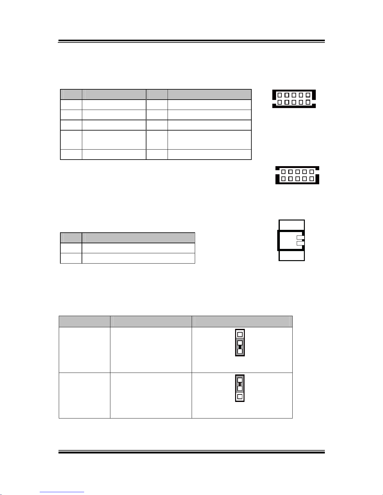
2-2-3. COM Connector
COM1-1, COM2-1, COM3-1, COM4-1, COM4-2: COM Connectors
PIN ASSIGNMENT PIN ASSIGNMENT
1 DCD 6 DSR
2 RXD 7 RTS
3 TXD 8 CTS
4 DTR 9 RI/+5V/+12V selectable
(Max. current: 1A)
5 GND 10 NC
Note:
Each COM connector is selectable for RI/+5V/+12V.
For details, refer to COM Port RI & Voltage Selection.
2-2-4. i-Button Connector
JI_BUTTON1: i-Button Connector
PIN ASSIGNMENT
1 COM3_DTR_R_I
2 COM3_RXD_R_I
2-2-5. COM3 / i-Button Function Selection
JP20, JP21, JP22: COM3 / i-Button Function Connectors
SELECTION JUMPER SETTING JUMPER ILLUSTRATION
COM 3 1-2
1
3
JP20/JP21/JP22/
i-Button* 2-3
1
3
JP20/JP21/JP22/
Note: Manufacturing Default is COM3.
*COM3 & COM3-1 will not function when jumpers JP20, JP21 & JP22 are set as “i-Button.”
1
2
JI_BUTTON1
51
10
6
COM1-1/
COM2-1/
COM3-1/
COM4-1/
6
10
1
5
COM4-2/
Chapter 2 System Configuration
PA-3122 SERIES USER’S MANUAL
Page: 2-13
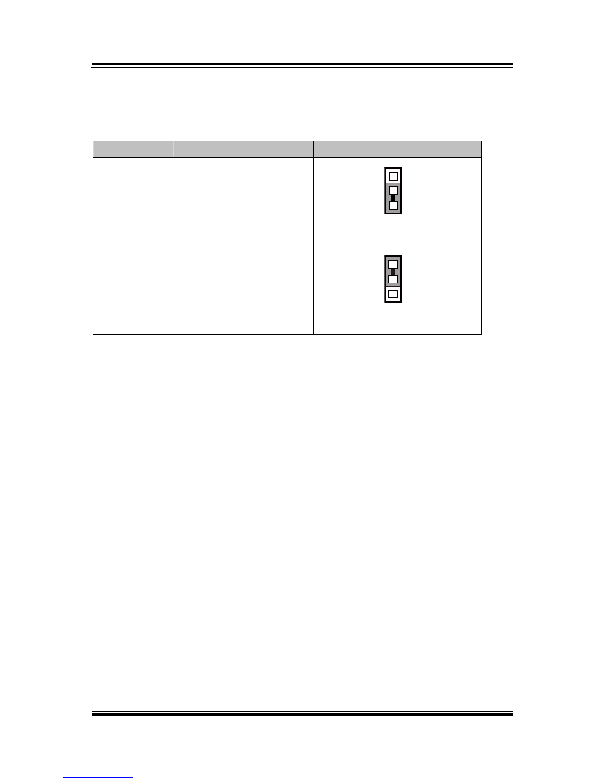
2-2-6. Cash Drawer Control Selection
JP37: Cash Drawer control connector
SELECTION JUMPER SETTING JUMPER ILLUSTRATION
Cash Drawer
Open
1-2
1
3
JP37
GND 2-3
1
3
JP37
Note: Manufacturing Default is GND.

Chapter 2 System Configuration
PA-3122 SERIES USER’S MANUAL
Page: 2-14
2-2-7. Cash Drawer Power Selection
JP29: Cash Drawer power selection
SELECTION JUMPER SETTING JUMPER ILLUSTRATION
+24V 1-2
3
1
JP29
+12V 2-3
3
1
JP29
Note: Manufacturing Default is +12V.
Caution:
1. Voltage of the external cash drawer port DRW1 is adjustable on BIOS or with the
corresponding jumper JP29. Either way cannot be applied simultaneously in case of system
error, component damage or serious boot failure.
That is, JP29 will be enabled if DRW1 is disabled on BIOS.
2. There is no pin connection for JP29 by default. Refer to Voltage Adjust Configuration in
chapter 3 for detailed BIOS setting (BIOS default at 12V).

Chapter 2 System Configuration
PA-3122 SERIES USER’S MANUAL
Page: 2-15
2-2-8. USB Connector
USB1, USB2, USB6, USB7: USB 2.0 connector
PIN ASSIGNMENT
1 5V (Maximum current: 0.5A)
2 D3 D+
4 GND
5 GND
Note: USB1 would be used when jumpers
JP14 & JP15 are set as 1-2 (short)
connected.
2-2-9. LED Connector
LED1-1: Power indication LED connector
PIN ASSIGNMENT
1 GND
2 PWR_LED
2 1
LED1-1
15
USB1/
USB2/
USB7/
1
5
USB6

Chapter 2 System Configuration
PA-3122 SERIES USER’S MANUAL
Page: 2-16
2-2-10. Power Connector
DC12V_PWR1: DC 12Voltage Provider Connector
PIN ASSIGNMENT
1 VCC12
2 GND
3 VCC12
DC5V_PWR1: DC 5Voltage Provider Connector
PIN ASSIGNMENT
1 5V
2 GND
2-2-11. Power for Thermal Printer Connector
PRT_PWR1: Power for Thermal Printer Connector
PIN ASSIGNMENT
1 VCC24SB
2 VCC24SB
3 GND
4 GND
2-2-12. External Speaker Connector
SPK1: External speaker connector
PIN ASSIGNMENT
1 SPK_GND
2 SPK_OUT
1 3
DC12V_PWR1
1 4
PRT_PWR1
12
SPK1
12
DC5V_PWR1

Chapter 2 System Configuration
PA-3122 SERIES USER’S MANUAL
Page: 2-17
2-2-13. Inverter Connector
JINV4: Inverter connectors
PIN ASSIGNMENT
1 +12V
2 +12V
3 GND
4 BRCTR
5 GND
6 LVDS_BKLTEN
2-2-14. LED Backlight Power Control Selection
JP12: LED backlight power control connectors
(for LED backlight panel without power driver built-in)
SELECTION JUMPER SETTING JUMPER ILLUSTRATION
On
1-3
2-4
2
1
6
5
JP12
Off
3-5
4-6
2
1
6
5
JP12
Note: Manufacturing Default is LED.
16
JINV4

Chapter 2 System Configuration
PA-3122 SERIES USER’S MANUAL
Page: 2-18
2-2-15. LED Backlight Power Connector
JINVDRV1: LED backlight power connector
PIN ASSIGNMENT
1 VCC
2 GND
Note: JINVDRV1 will not function when
JP38 & JP39 are set as “RS-232”
interface.
2-2-16. Panel Resolution Selection
JP8, JP9: Panel resolution control connectors
SELECTION JUMPER
SETTING
JUMPER ILLUSTRATION
15”
1024 x 768
(24 bit)
JP8: 1-3, 4-6
JP9: 3-5, 4-6
2
1
6
5
JP8
2
1
6
5
JP9
10.4”
1024 x 768
(18 bit)
JP8: 3-5, 2-4
JP9:3-5, 4-6
2
1
6
5
JP8
2
1
6
5
JP9
10.4”
800 x 600
(18bit)
JP8: 3-5, 4-6
JP9: 3-5, 4-6
2
1
6
5
JP8
2
1
6
5
JP9
Note: Manufacturing Default is 10.4”, 1024 x 768 (18bit).
12
JINVDRV1

Chapter 2 System Configuration
PA-3122 SERIES USER’S MANUAL
Page: 2-19
2-2-17. LVDS Connector
LVDS1: LVDS Connector
PIN ASSIGNMENT PIN ASSIGNMENT
1 LVDS_VCC 16 LVDS_CLKA_D+
2 GND 17 VDS_CLKA_D3 NC 18 GND
4 NC 19 LVDS_A2_D+
5 GND 20 LVDS_A2_D6 LVDS_B2_D- 21 GND
7 LVDS_B2_D+ 22 LVDS_A1_D+
8 GND 23 LVDS_A1_D9 LVDS_B1_D- 24 GND
10 LVDS_B1_D+ 25 LVDS_A0_D+
11 LVDS_B3_D+ 26 LVDS_A0_D12 LVDS_B3_D- 27 LVDS_A3_D+
13 LVDS_B0_D+ 28 LVDS_A3_D14 LVDS_B0_D- 29 LVDS_VCC
15 GND 30 LVDS_VCC
2-2-18. Touch Panel Connector
TOUCH3: Touch panel connectors
PIN ASSIGNMENT PIN ASSIGNMENT
1 LR (Low Right) 4 UR (Up Right)
2 LL (Low Left) 5 UL (Up Left)
3 Probe
2
1 29
30
LVDS1
1
5
TOUCH3

Chapter 2 System Configuration
PA-3122 SERIES USER’S MANUAL
Page: 2-20
2-2-19. Touch Panel Signal Interface Selection
JP14, JP15, JP38, JP39: Control connectors for touch panel signal interface
SELECTION JUMPER
SETTING
JUMPER ILLUSTRATION
USB1
Connector
JP14: 1-2
JP15: 1-2
JP38: 2-3
JP39: 2-3
1
3
JP14
1
3
JP15
3
1
JP38
3
1
JP39
USB
Interface
JP14: 2-3
JP15: 2-3
JP38: 2-3
JP39: 2-3
1
3
JP14
1
3
JP15
3
1
JP38
3
1
JP39
RS-232
Interface
JP14: 1-2
JP15: 1-2
JP38: 1-2
JP39: 1-2
1
3
JP14
1
3
JP15
3
1
JP38
3
1
JP39
Note: 1. Manufacturing Default is USB.
2. The COM2 & COM2-1 connector will not function when JP38 & JP39 are set
as 1-2 connected.
3. USB1 connector when JP14 & JP15 are set as 1-2 connected.

Chapter 2 System Configuration
PA-3122 SERIES USER’S MANUAL
Page: 2-21
2-2-20. Clear CMOS Data Selection
JP3: Clear CMOS data selection
SELECTION JUMPER SETTING JUMPER ILLUSTRATION
Normal Open
1
JP3
Clear CMOS*
1-2
1
JP3
Note: Manufacturing Default is Normal.
*To clear CMOS data, you must power-off the computer and set the jumper to “Clear CMOS” as
illustrated above. After five to six seconds, set the jumper back to “Normal” and power-on the
computer.
2-2-21. MSR/Card Reader Connector
PS/2_2: MSR/Card reader connectors
PIN ASSIGNMENT
1 KB_CLK (Output)
2 KB_CLK_C (Input)
3 KB_DATA_C (Input)
4 KB_DATA (Output)
5 +5V
6 GND
6
1
PS/2_2

Chapter 2 System Configuration
PA-3122 SERIES USER’S MANUAL
Page: 2-22
2-2-22. SATA & SATA Power Connector
SATA1, SATA2: Serial ATA connectors
PIN ASSIGNMENT PIN ASSIGNMENT
1 G1 5 RX2 TX+ 6 RX+
3 TX- 7 G3
4 G2
Note: SATA1 only supports the optional RAID
function on board.
JPWR_4P1, JPWR_4P2: Serial ATA power connectors
PIN ASSIGNMENT
1 VCC
2 GND
3 GND
4 VCC12
Note: JPWR_4P1 only supports the
optional RAID function on board.
1 7
SATA1/
SATA2/
1 4
JPWR_4P1/
JPWR_4P2/

Chapter 2 System Configuration
PA-3122 SERIES USER’S MANUAL
Page: 2-23
2-2-23. Printer Connector
LPT1: Printer connector
PIN ASSIGNMENT PIN ASSIGNMENT
1 STBJ 14 ALFJ
2 PDR0 15 ERRJ
3 PDR1 16 PAR_INITJ
4 PDR2 17 SLCTINJ
5 PDR3 18 GND
6 PDR4 19 GND
7 PDR5 20 GND
8 PDR6 21 GND
9 PDR7 22 GND
10 ACKJ 23 GND
11 BUSY 24 GND
12 PE 25 GND
13 SLCTJ 26 NC
26
13
14
1
LPT1

Chapter 2 System Configuration
PA-3122 SERIES USER’S MANUAL
Page: 2-24
2-2-24.
Mini-PCIe / m
SATA Connector
SLOT1: Mini-PCIe connector, not support USB function
PIN ASSIGNMENT PIN ASSIGNMENT
1 WAKE# 27 GND
2 +3.3V 28 +1.5V
3 Reserved 29 GND
4 GND 30 SMB_CLK
5 Reserved 31 PETn2
6 +1.5V 32 SMB_DATA
7 CLKREQ# 33 PETp2
8 Reserved 34 GND
9 GND 35 GND
10 Reserved 36 NC
11 REFCLK1- 37 GND
12 Reserved 38 NC
13 REFCLK1+ 39 +3.3V
14 Reserved 40 GND
15 GND 41 +3.3V
16 Reserved 42 Reserved
17 Reserved 43 GND
18 GND 44 Reserved
19 Reserved 45 NC
20 Reserved 46 Reserved
21 GND 47 NC
22 PERST# 48 +1.5V
23 PERn2 49 NC
24 +3.3SB 50 GND
25 PERp2 51 Reserved
26 GND 52 +3.3V
12151617
18
51
52
SLOT1

Chapter 2 System Configuration
PA-3122 SERIES USER’S MANUAL
Page: 2-25
SLOT2: Mini-PCIe or mSATA connector, support USB function
PIN ASSIGNMENT PIN ASSIGNMENT
1 WAKE# 27 GND
2 +3.3V 28 +1.5V
3 Reserved 29 GND
4 GND 30 SMB_CLK
5 Reserved 31 PETn0/SATA1_TX-
6 +1.5V 32 SMB_DATA
7 CLKREQ# 33 PETp0/SATA1_TX+
8 Reserved 34 GND
9 GND 35 GND
10 Reserved 36 USB_D-
11 REFCLK0- 37 GND
12 Reserved 38 USB_D+
13 REFCLK0+ 39 +3.3V
14 Reserved 40 GND
15 GND 41 +3.3V
16 Reserved 42 Reserved
17 Reserved 43 GND
18 GND 44 Reserved
19 Reserved 45 NC
20 Reserved 46 Reserved
21 GND 47 NC
22 PERST# 48 +1.5V
23 PERn0/SATA1_RX+ 49 NC
24 +3.3SB 50 GND
25 PERp0/SATA1_RX- 51 Reserved
26 GND 52 +3.3V
12
1516
1718
5152
SLOT2

Chapter 2 System Configuration
PA-3122 SERIES USER’S MANUAL
Page: 2-26
2-3. PRINTER BOARD COMPONENT LOCATIONS & PIN
ASSIGNMENT
2-3-1. Printer Board: PDAC-3100
CN5
CN8
CN7
CN6
CN3
CN1
14
1
1
13
7
1
12
CN2
1
50
1
5
1
4
PDAC-3100 Printer Board Component Locations

Chapter 2 System Configuration
PA-3122 SERIES USER’S MANUAL
Page: 2-27
2-3-1-1. Power Supply Connector
CN1: Power supply wafer
PIN ASSIGNMENT
1 +24V
2 +24V
3 GND
4 GND
2-3-1-2. RS-232 Interface Connector
CN7: RS-232 interface connector
PIN ASSIGNMENT PIN ASSIGNMENT
1 TXD 5 DTR
2 RXD 6 DSR
3 RTS 7 GND
4 CTS
4
1
CN1
1
7
CN7

Chapter 2 System Configuration
PA-3122 SERIES USER’S MANUAL
Page: 2-28
2-3-1-3. Auto-Cutter Connector
CN3: Auto-cutter wafer
PIN ASSIGNMENT FUNCTION
1 NC Unused
2 Vcs Power supply of the home
position sensor
3 GND GND of the home position
sensor
4 CUTS Signal of the hom position
sensor
5 2B-1 Auto-cutter motor drive signal
6 2B-2 Auto-cutter motor drive signal
7 2A-1 Auto-cutter motor drive signal
8 2A-2 Auto-cutter motor drive signal
9 1B-1 Auto-cutter motor drive signal
10 1B-2 Auto-cutter motor drive signal
11 1A-1 Auto-cutter motor drive signal
12 1A-2 Auto-cutter motor drive signal
2-3-1-4. USB Connector
CN8: USB Connector
PIN ASSIGNMENT PIN ASSIGNMENT
1 Vbus 4 NC
2 D- 5 GND
3 D+
1
5
CN8
1
12
CN3

Chapter 2 System Configuration
PA-3122 SERIES USER’S MANUAL
Page: 2-29
2-3-1-5. Thermal Head/Motor/Sensor Connector
CN2: Thermal head/motor/sensor connector
PIN ASSIGNMENT FUNCTION
1 24V Head drive power
2 24V Head drive power
3 24V Head drive power
4 24V Head drive power
5 24V Head drive power
6 24V Head drive power
7 DAT Print data output
8 CLK Synchronizing signal for print
data transfer
9 GND Head GND
10 GND Head GND
11 GND Head GND
12 GND Head GND
13 GND Head GND
14 GND Head GND
15 NC Unused
16 DST4 Head strobe signal
17 DST3 Head strobe signal
18 3.3V Logic Power
19 GND Thermistor GND
20 GND Thermistor GND
21 TH Thermistor signal
22 NC Unused
23 DST2 Head strobe signal
24 DST1 Head strobe signal
25 GND Head GND
26 GND Head GND
27 GND Head GND
28 GND Head GND
29 GND Head GND
1
50
CN2

Chapter 2 System Configuration
PA-3122 SERIES USER’S MANUAL
Page: 2-30
PIN ASSIGNMENT FUNCTION
30 GND Head GND
31 LATCH Print data latch
32 24V Head drive power
33 24V Head drive power
34 24V Head drive power
35 24V Head drive power
36 24V Head drive power
37 24V Head drive power
38 NC Unused
39 PS Signal of the out-of-paper
sensor
40 Vps Power supply of the out-of-
paper sensor
41 GND GND of the platen position/
out-of-paper sensor
42 HS Signal of the platen position
sensor
43 NC Unused
44 FG Frame GND
45 FG Frame GND
46 NC Unused
47 2A Motor drive signal
48 1B Motor drive signal
49 1A Motor drive signal
50 2B Motor drive signal

Chapter 2 System Configuration
PA-3122 SERIES USER’S MANUAL
Page: 2-31
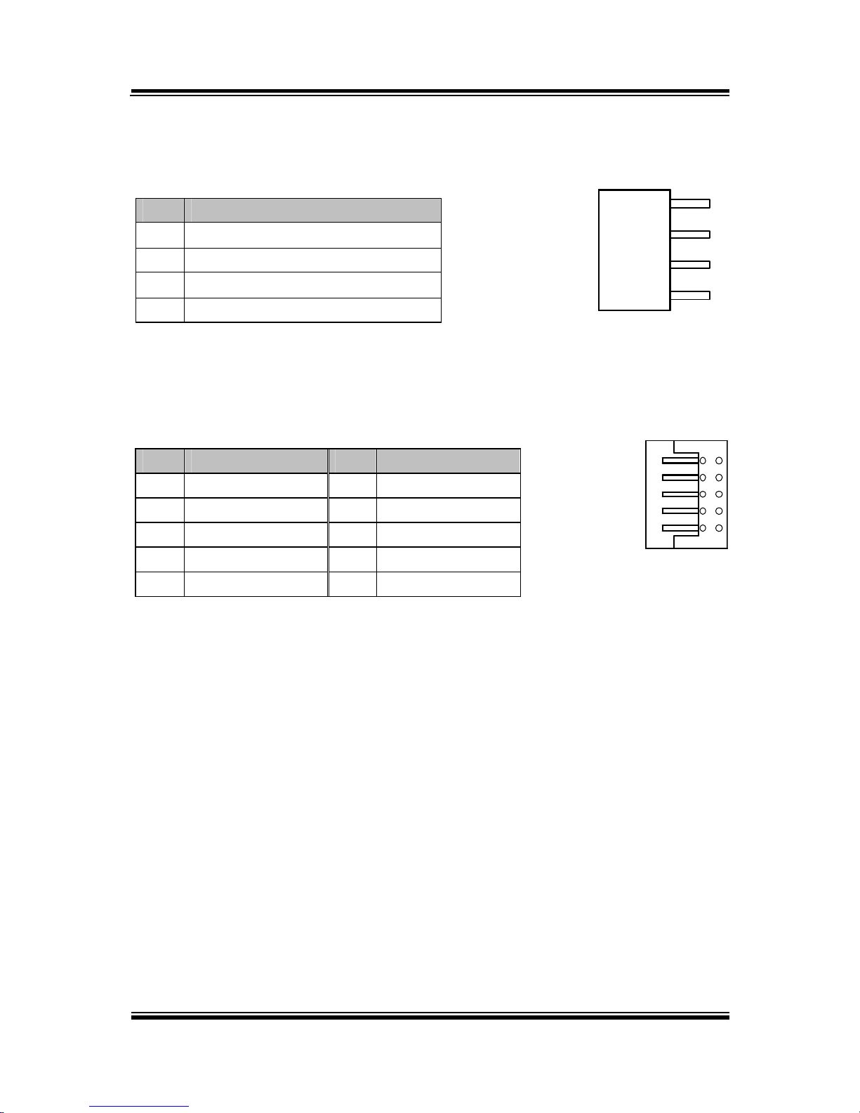
2-3-1-6. Terminal Assignment Connector
CN5: Terminal assignment connector
PIN ASSIGNMENT FUNCTION
1 FEED Feed signal
2 RESET Reset signal
3 GND GND
4 ST1 Status signal
5 ST2
Status signal
6 ST3
Status signal
7 ST4
Status signal
8 GND GND
9 DRS Drawer sensor signal
10 DSW Drawer switch signal
11 Vdu Drive terminal for the drawer
(Vp side)
12 GNDdu Drive terminal for the drawer
(GND side)
13 GND GND
14 NC Unused
14
1
CN5

Chapter 2 System Configuration
PA-3122 SERIES USER’S MANUAL
Page: 2-32
2-3-2. Printer Board: MB-1030
1
1
5
13
4
CN3
CN2
4
14
1
1
1
50
12
1
1
9 10
2
CN1
CUT_CN1
PRINT_CN1
COM1
USB_CN1
24V_CN1
MB-1030 Printer Board Component Locations
Chapter 2 System Configuration
PA-3122 SERIES USER’S MANUAL
Page: 2-33
2-3-2-1. Power Supply Connector
24V_CN1: Power Supply Wafer
PIN ASSIGNMENT
1 GND
2 GND
3 +24V
4 +24V
2-3-2-2. RS-232 Interface Connector
COM1: RS-232 Interface Connector
PIN ASSIGNMENT PIN ASSIGNMENT
1
NC
6
DSR /CTS
2 RXD 7
RTS
3 TXD 8
CTS
4 DTR /RTS 9
NC
5 GND 10
NC
4
1
24V_CN1
1
9 10
2
COM1

Chapter 2 System Configuration
PA-3122 SERIES USER’S MANUAL
Page: 2-34
2-3-2-3.
Thermal Head/Motor/Sensor Connector
PRINT_CN1: Thermal head/motor/sensor connector
PIN ASSIGNMENT FUNCTION
1 24V Head drive power
2 24V Head drive power
3 24V Head drive power
4 24V Head drive power
5 24V Head drive power
6 24V Head drive power
7 DAT Print data output
8 CLK Synchronizing signal for print
data transfer
9 GND Head GND
10 GND Head GND
11 GND Head GND
12 GND Head GND
13 GND Head GND
14 GND Head GND
15 NC Unused
16 DST4 Head strobe signal
17 DST3 Head strobe signal
18 3.3V Logic Power
19 GND Thermistor GND
20 GND Thermistor GND
21 TH Thermistor signal
22 NC Unused
23 DST2 Head strobe signal
24 DST1 Head strobe signal
25 GND Head GND
26 GND Head GND
27 GND Head GND
28 GND Head GND
29 GND Head GND
1
50
PRINT_CN1

Chapter 2 System Configuration
PA-3122 SERIES USER’S MANUAL
Page: 2-35
PIN ASSIGNMENT FUNCTION
30 GND Head GND
31 LATCH Print data latch
32 24V Head drive power
33 24V Head drive power
34 24V Head drive power
35 24V Head drive power
36 24V Head drive power
37 24V Head drive power
38 NC Unused
39 PS Signal of the out-of-paper
sensor
40 Vps Power supply of the out-of-
paper sensor
41 GND GND of the platen position/
out-of-paper sensor
42 HS Signal of the platen position
sensor
43 NC Unused
44 FG Frame GND
45 FG Frame GND
46 NC Unused
47 2A Motor drive signal
48 1B Motor drive signal
49 1A Motor drive signal
50 2B Motor drive signal

Chapter 2 System Configuration
PA-3122 SERIES USER’S MANUAL
Page: 2-36
2-3-2-4. Auto-Cutter Connector
CUT_CN1: Auto-cutter Connector
PIN ASSIGNMENT FUNCTION
1 NC Unused
2 Vcs Power supply of the home
position sensor
3 GND GND of the home position sensor
4 CUTS Signal of the hom position sensor
5 2B-1 Autocutter motor drive signal
6 2B-2 Autocutter motor drive signal
7 2A-1 Autocutter motor drive signal
8 2A-2 Autocutter motor drive signal
9 1B-1 Autocutter motor drive signal
10 1B-2 Autocutter motor drive signal
11 1A-1 Autocutter motor drive signal
12 1A-2 Autocutter motor drive signal
2-3-2-5. Paper-Near-END Sensor Connector
CN2: Paper-near-end sensor connector
PIN ASSIGNMENT FUNCTION
1 Vns Power supply of the near end
sensor
2 NS Signal of the near end sensor
3 GND GND of the near end sensor
12
1
CUT_CN1
13
CN2

Chapter 2 System Configuration
PA-3122 SERIES USER’S MANUAL
Page: 2-37
2-3-2-6. USB Interface Connector
USB_CN1: USB interface connector
PIN ASSIGNMENT PIN ASSIGNMENT
1 Vbus 4 GND
2 D- 5 GND
3 D+
2-3-2-7. Terminal Assignment Connector
CN1: Terminal assignment connector
PIN ASSIGNMENT FUNCTION
1 FEED Feed signal
2 RESET Reset signal
3 GND GND
4 ST1 Status signal
5 ST2
Status signal
6 ST3
Status signal
7 ST4
Status signal
8 GND GND
9 DRS Drawer sensor signal
10 DSW Drawer switch signal
11 Vdu Drive terminal for the drawer
(Vp side)
12 GNDdu Drive terminal for the drawer
(GND side)
13 GND GND
14 NC Unused
1
5
USB_CN1
14
1
CN1

Chapter 2 System Configuration
PA-3122 SERIES USER’S MANUAL
Page: 2-38
2-3-3. Printer Board: MB-1011 & MB-1013
CN7
CN3
CN2
CN5
CN1
1
1
14
1
1
12
50
7
4
1
MB-1011
MB-1013
CN8
1
5
MB-1011 & MB-1013 Printer Board Component Locations

Chapter 2 System Configuration
PA-3122 SERIES USER’S MANUAL
Page: 2-39
2-3-3-1. Power Supply Connector
CN1: Power supply wafer
PIN ASSIGNMENT
1 GND
2 GND
3 +24V
4 +24V
2-3-3-2. RS-232 Interface Connector
CN7: RS-232 interface connector
PIN ASSIGNMENT PIN ASSIGNMENT
1 TXD 5
DTR
2 RXD 6
DSR
3 RTS 7
GND
4 CTS
4
1
CN1
1
7
CN7

Chapter 2 System Configuration
PA-3122 SERIES USER’S MANUAL
Page: 2-40
2-3-3-3. Thermal Head/Motor/Sensor Connector
CN2: Thermal head/motor/sensor connector
PIN ASSIGNMENT FUNCTION
1 24V Head drive power
2 24V Head drive power
3 24V Head drive power
4 24V Head drive power
5 24V Head drive power
6 24V Head drive power
7 DAT Print data output
8 CLK Synchronizing signal for print
data transfer
9 GND Head GND
10 GND Head GND
11 GND Head GND
12 GND Head GND
13 GND Head GND
14 GND Head GND
15 NC Unused
16 DST4 Head strobe signal
17 DST3 Head strobe signal
18 3.3V Logic Power
19 GND Thermistor GND
20 GND Thermistor GND
21 TH Thermistor signal
22 NC Unused
23 DST2 Head strobe signal
24 DST1 Head strobe signal
25 GND Head GND
26 GND Head GND
27 GND Head GND
28 GND Head GND
29 GND Head GND
1
50
CN2

Chapter 2 System Configuration
PA-3122 SERIES USER’S MANUAL
Page: 2-41
PIN ASSIGNMENT FUNCTION
30 GND Head GND
31 LATCH Print data latch
32 24V Head drive power
33 24V Head drive power
34 24V Head drive power
35 24V Head drive power
36 24V Head drive power
37 24V Head drive power
38 NC Unused
39 PS Signal of the out-of-paper
sensor
40 Vps Power supply of the out-of-
paper sensor
41 GND GND of the platen position/
out-of-paper sensor
42 HS Signal of the platen position
sensor
43 NC Unused
44 FG Frame GND
45 FG Frame GND
46 NC Unused
47 2A Motor drive signal
48 1B Motor drive signal
49 1A Motor drive signal
50 2B Motor drive signal

Chapter 2 System Configuration
PA-3122 SERIES USER’S MANUAL
Page: 2-42
2-3-3-4. Auto-Cutter Connector
CN3: Auto-cutter Connector
PIN ASSIGNMENT FUNCTION
1 NC Unused
2 Vcs Power supply of the home
position sensor
3 GND GND of the home position sensor
4 CUTS Signal of the hom position sensor
5 2B-1 Autocutter motor drive signal
6 2B-2 Autocutter motor drive signal
7 2A-1 Autocutter motor drive signal
8 2A-2 Autocutter motor drive signal
9 1B-1 Autocutter motor drive signal
10 1B-2 Autocutter motor drive signal
11 1A-1 Autocutter motor drive signal
12 1A-2 Autocutter motor drive signal
2-3-3-5. USB Interface Connector
CN8: USB interface connector
PIN ASSIGNMENT
1 Vbus
2 D3 D+
4 GND
5 GND
12
1
CN3
1
5
CN8

Chapter 2 System Configuration
PA-3122 SERIES USER’S MANUAL
Page: 2-43
2-3-3-6. Terminal Assignment Connector
CN5: Terminal assignment connector
PIN ASSIGNMENT FUNCTION
1 FEED Feed signal
2 RESET Reset signal
3 GND GND
4 ST1 Status signal
5 ST2 Status signal
6 ST3 Status signal
7 ST4 Status signal
8 GND GND
9 DRS Drawer sensor signal
10 DSW Drawer switch signal
11 Vdu Drive terminal for the drawer
(Vp side)
12 GNDdu Drive terminal for the drawer
(GND side)
13 GND GND
14 NC Unused
1
14
CN5

Chapter 2 System Configuration
PA-3122 SERIES USER’S MANUAL
Page: 2-44
2-4. VFD BOARD COMPONENT LOCATIONS & PIN ASSIGNMENT
2-4-1. VFD Board: MB-4103, LD720
JP12V
CN1
1
1
16
MB-4103 & LD720 VFD Board Component Locations

Chapter 2 System Configuration
PA-3122 SERIES USER’S MANUAL
Page: 2-45
2-4-1-1. Power Switch Selection
JP12V: Power Switch Selection
SELECTION JUMPER SETTING JUMPER ILLUSTRATION
OFF 1-2
3
1
JP12V
ON 2-3
3
1
JP12V
Note: Manufacturing Default is ON.
2-4-1-2. RS-232 Serial Interface Connector
CN1: RS-232 serial interface wafer
PIN ASSIGNMENT PIN ASSIGNMENT
1 GND 9 NC
2 TXD 10 NC
3 RXD 11 NC
4 DTR 12 NC
5 DSR 13 NC
6 RTS 14 NC
7 CTS 15 NC
8 +12V/+5V 16 NC
1
16
CN1

Chapter 2 System Configuration
PA-3122 SERIES USER’S MANUAL
Page: 2-46
2-5. MSR BOARD COMPONENT LOCATIONS & PIN ASSIGN-
MENT
2-5-1. ID TECH
1
7
CN
ID-TECH MSR Board Component Locations
2-5-1-1. Main Connector
CN:
PIN ASSIGNMENT PIN ASSIGNMENT
1 Chassis Ground 5
K-CLK
(Computer connections)
2 P-CLK
(Keyboard connections)
6 K-DATA
(Computer connections)
3 P-DATA
(Keyboard connections)
7 GND
4 +5V Vcc
1
7
CN

Chapter 2 System Configuration
PA-3122 SERIES USER’S MANUAL
Page: 2-47
2-5-2. SYSKING
112
CN
SYSKING MSR Board Component Locations
2-5-2-1. Main Connector
CN:
PIN ASSIGNMENT PIN ASSIGNMENT
1 +5V Vcc 7 NC
2 K-DATA
(Host to MSR)
8 NC
3 K-CLK
Host to MSR
9 NC
4 P-DATA
(MSR to Keyboard)
10 NC
5 P-CLK
(MSR to Keyboard)
11 Signal Ground
6 NC 12 Signal Ground
112
CN

Chapter 2 System Configuration
PA-3122 SERIES USER’S MANUAL
Page: 2-48
2-5-3. MB-3012
IO1
I_BUTTON1
1 12
1
2
MB-3012 MSR Board Component Locations
2-5-3-1. Information Button Reader
I_BUTTON1: Information button reader
PIN ASSIGNMENT
1
I_B1
2 GND
2-5-3-2. Output Connector
IO1: Output wafer
PIN ASSIGNMENT PIN ASSIGNMENT
1 CLK_KB 7
RX_MSR
2 CLK_PC 8 TX_MSR
3 DATA_KB 9 GND
4 DATA_PC 10 USB_D+_R
5 +5V 11 USB_D-_R
6 CHASSIS GND 12 GND
1
2
I-BUTTON1
1 12
IO1

Page: 3-1
SOFTWARE
This chapter provides the detailed information of driver utilities and
BIOS settings for the system.
Sections included:
Driver
- Intel® Chipset Software Installation Utility
- VGA Driver Utility
- LAN Driver Utility
- Sound Driver Utility
- Touchsreen Driver Utility
- Fingerprinter Driver Utility (Optional)
- RFID Module Driver (Optional)
- Wireless Module Driver (Optional)
Embedded Peripheral Device
- Printer
- VFD
- MSR
API
BIOS Operation
- Setup
- Watchdog Timer Configuration
- Update Procedure
- System Resource Map
CHAPTER
3

Chapter 3 Software
PA-3122 SERIES USER′S MANUAL
Page:3-2
3-1. DRIVER
3-1-1. Introduction
Enclosed with the PA-3122 Series package is our driver utilities, which comes in a
CD-ROM format. Refer to the following table for driver locations.
FILENAME
(Assume that CD ROM drive is D:)
PURPOSE
D:\Driver\Plaform\POSReady7 (32/64-bit)\
Intel TXE Firmware
D:\Driver\Plaform\Win8(32/64bit)\Intel TXE
Firmware
Intel® TXE firmware driver
D:\Driver\Plaform\POSReady7 (32-bit)\MBI
Driver
D:\Driver\Plaform\Win8(32/64bit)\MBI Driver
Intel® MBI driver
D:\Driver\Plaform\POSReady7 (32-bit)\Main
Chip
D:\Driver\Plaform\Win8(32/64bit)\Main Chip
Intel® chipset software installation
utility
D:\Driver\Plaform\POSReady7 (32-bit)\VGA
D:\Driver\Plaform\Win8(32/64bit)\VGA
Intel® HD Graphics family for
VGA driver installation
D:\Driver\Plaform\POSReady7 (32-bit)\LAN
D:\Driver\Plaform\Win8(32/64bit)\LAN
Realtek 8119CG for LAN driver
installation
D:\Driver\Plaform\POSReady7 (32-
bit)\SOUND
D:\Driver\Plaform\Win8(32/64bit)\SOUND
Realtek ALC888 for sound driver
installation
D:\Driver\Device. Driver installation for touch-
screen, embedded printer, MSR,
wireless card, & fingerprint
D:\Driver\Flash BIOS AMI BIOS update utility
Note: Be sure to install the driver utilities right after the OS is fully installed.

Chapter 3 Software
PA-3122 SERIES USER′S MANUAL
Page:3-3
3-1-2. Intel® Chipset Software Installation Utility
3-1-2-1. Introduction
The Intel® Chipset Software Installation Utility installs Windows *.INF files to the
target system. These files outline to the operating system how to configure the Intel
chipset components in order to ensure the following features function properly:
SATA Storage Support (SATA & SATA II)
USB Support (1.1 & 2.0)
Identification of Intel® Chipset Components in Device Manager
3-1-2-2. Installation of Intel® Chipset Driver
The utility pack is to be installed only for POSReady 7 & Embedded 8 Industry
series, and it should be installed right after the OS installation. Please follow the
steps below:
1. Connect the USB CD-ROM device to PA-3122 and insert the driver disk.
2. Enter the “Main Chip” folder where the Chipset driver is located (depending
on your OS platform).
3. Click Setup.exe file for driver installation.
4. Follow the on-screen instructions to complete the installation.
5. Once installation is completed, shut down the system and restart PA-3122 for
the changes to take effect.

Chapter 3 Software
PA-3122 SERIES USER′S MANUAL
Page:3-4
3-1-3. VGA Driver Utility
The VGA interface embedded with PA-3122 can support a wide range of display
types. You can have dual displays via CRT & LVDS interfaces work
simultaneously.
3-1-3-1. Installation of VGA Driver
To install the Graphics driver, follow the steps below:
1. Connect the USB-CD ROM device to PA-3122 and insert the driver disk.
2. Enter the “VGA” folder where the VGA driver is located (depending on your
OS platform).
3. Click Setup.exe file for driver installation.
4. Follow the on-screen instructions to complete the installation.
5. Once installation is completed, shut down the system and restart PA-3122 for
the changes to take effect.
3-1-4. LAN Driver Utility
PA-3122 is enhanced with LAN function that can support various network adapters.
Installation platform for the LAN driver is listed as follows:
3-1-4-1. Installation of LAN Driver
To install the LAN Driver, follow the steps below:
1. Connect the USB CD-ROM device to PA-3122 and insert the driver disk.
2. Enter the “LAN” folder where the LAN driver is located (depending on your OS
platform).
3. Click Setup.exe file for driver installation.
4. Follow the on-screen instructions to complete the installation.
5. Once installation is completed, shut down the system and restart PA-3122 for the
changes to take effect.
For more details on the Installation procedure, please refer to the Readme.txt file
found on LAN Driver Utility.

Chapter 3 Software
PA-3122 SERIES USER′S MANUAL
Page:3-5
3-1-5. Sound Driver Utility
The sound function enhanced in this system is fully compatible with Windows
POSReady 7 & Embedded 8 Industry series. Below, you will find the content of the
Sound driver.
3-1-5-1. Installation of Sound Driver
To install the Sound Driver, follow the steps below:
1. Connect the USB CD-ROM device to PA-3122 and insert the driver disk.
2. Enter the “Sound” folder where the sound driver is located (depending on your
OS platform).
3. Click Setup.exe file for driver installation.
4. Follow the on-screen instructions to complete the installation.
5. Once installation is completed, shut down the system and restart PA-3122 for the
changes to take effect.
3-1-6. Touchscreen Driver Utility
The touchscreen driver utility can only be installed on Windows POSReady 7 &
Embedded 8 Industry series, and it should be installed right after the OS installation.
3-1-6-1. Installation of Touchscreen Driver
To install the touchscreen driver, follow the steps below:
1. Connect the USB CD-ROM device to PA-3122 and insert the driver disk.
2. Enter the “Device\Touch Screen” folder where the touchscreen driver is located.
3. Click Setup.exe file for driver installation.
4. Follow the on-screen instructions to complete the installation.
5. Once installation is completed, shut down the system and restart PA-3122 for the
changes to take effect.

Chapter 3 Software
PA-3122 SERIES USER′S MANUAL
Page:3-6
3-1-7. Fingerprinter Driver Utility (Optional)
The fingerprinter driver utility can only be installed on a Windows platform, and it
should be installed right after the OS installation.
3-1-7-1. Installation of Fingerprinter Driver
To install the fingerprinter driver, follow the steps below:
1. Connect the USB CD-ROM device to PA-3122 and insert the driver disk.
2. Enter the “Device\Embedded Finger Printer” folder where the fingerprinter
driver is located.
3. Click Setup.exe file for driver installation.
4. Follow the on-screen instructions to complete the installation.
5. Once installation is completed, shut down the system and restart PA-3122 for the
changes to take effect.
3-1-8. RFID Module Driver Utility (Optional)
The RFID driver utility can only be installed on Windows POSReady7 &
Embedded 8 industry series, and it should be installed right after the OS installation.
3-1-8-1. Installation of |RFID Module Driver
To install the fingerprinter driver, follow the steps below:
1. Connect the USB CD-ROM device to PA-3122 and insert the driver disk.
2. Enter the “Device\RFID Module” folder where the RFID Module driver is located.
3. Click Autorun.exe file for driver installation.
4. Select Mifare Demo Software V1.5R8.
5. Follow the on-screen instructions to complete the installation.
6. Once installation is completed, shut down the system and restart PA-3122 for the
changes to take effect.

Chapter 3 Software
PA-3122 SERIES USER′S MANUAL
Page:3-7
3-1-9. Wireless Module Driver Utility (Optional)
The wireless driver utility can only be installed on Windows POSReady7 &
Embedded 8 Industry series, and it should be installed right after the OS installation.
3-1-9-1. Installation of Wireless Driver
To install the wireless driver, follow the steps below:
1. Connect the USB CD-ROM device to PA-3122 and insert the driver disk.
2. Enter the “Device\Embedded Wireless Module” folder where the wireless driver
is located.
3. Click Setup.exe file for driver installation.
4. Follow the on-screen instructions to complete the installation.
5. Once installation is completed, shut down the system and restart PA-3122 for the
changes to take effect.

Chapter 3 Software
PA-3122 SERIES USER′S MANUAL
Page:3-8
3-2. EMBEDDED PERIPHERAL DEVICES
Command lists and driver installation guide for embedded peripheral devices of the
system - printer board, VFD and MSR – are explicitly included in this section.
3-2-1. Printer Board: MB-1030
3-2-1-1. Command List
1. Printer Registry Operation
Registry path: [HKEY_LOCAL_MACHINE\SOFTWARE\OLEforRetail\ServiceOPOS\
PosPrinter\MB1030]
Registry Name Default Data Notes
Default Value MB1030
OPOS.MB1030.1
-
BaudRate 115200 BitLength 8 Parity 0 Port COM4 Stop 1 -
2. POS Printer Service Object and Method Relations
Method Status of support Notes
Open ○ Close ○ ClaimDevice ○ ReleaseDevice ○ Enable ○ Disable ○ CheckHealth ○ PrintNormal ○ PrintBarCode ○ PrintBitmap ○ RotatePrint ○ only support 180°
CutPaper ○ -

Chapter 3 Software
PA-3122 SERIES USER′S MANUAL
Page:3-9
3-2-1-2. OPOS Printer Driver
The MB1030_OposSetup.exe program sets up the registry information of MSRHK
reader for OPOS program uses.
1. Installation
Below steps guide you to install the MB1030_OposSetup program.
Run the setup file MB1030_OposSetup.exe located in the Software folder of CD.
This setup also installs the MB1030 program.
Follow the wizard instructions to complete the installation.
2. Launching Program
Below steps guide you to load the MB1030 program.
Click POSPrinter folder from the path Start\Programs\Protech OPOS.
Click MB1030 to launch the program.

Chapter 3 Software
PA-3122 SERIES USER′S MANUAL
Page:3-10
3. OPOS Control Object of MB1030 Program
a.) Print tab buttons:
Button/Item Description
Printer Normal Print the string.
b.) Bitmap tab buttons/items:
Button/Item Description
Load Load bitmap file.
Print Bitmap Print bitmap file.
Type Normal or Rotate 108˚.

Chapter 3 Software
PA-3122 SERIES USER′S MANUAL
Page:3-11
c.) BarCode tab buttons/items:
Button/Item Description
Print BarCode Print the barcode.
Supported barcode types: UPCA, UPCE, EAN8, EAN13,
ITF, Codabar, Code39, Code93, Code128
Alignment Left, center or right
Position Print barcode number (None, Above or Below)
4. MB1030 type
Key Name Type Default Value Note
BaudRate String 115200 UART Baud Rate (default)
BitLength String 8 UART Data Bit (default)
Parity String 0 UART Parity Bit (default)
Port String COM4 UART Port (default)
Stop String 1 UART Stop Bit (default)

Chapter 3 Software
PA-3122 SERIES USER′S MANUAL
Page:3-12
5. OPOS APIs Support List
Category
Type
Name Mutability OPOS
APG
Version
Printer .SO
Properties common bool AutoDisable R/W 1.2 Not Applicable
Properties common long BinaryConversion R/W 1.2 Not Applicable
Properties common long CapPowerReporting Read only 1.3 Not Applicable
Properties common
string
CheckHealthText Read only 1.0 Supported
Properties common bool Claimed Read only 1.0 Supported
Properties common long DataCount Read only 1.2 Not Applicable
Properties common bool DataEventEnabled Read only 1.0 Not Applicable
Properties common bool DeviceEnabled R/W 1.0 Not Applicable
Properties common bool FreezeEvents R/W 1.0 Supported
Properties common long OpenResult Read only 1.5 Supported
Properties common bool OutputID Read only 1.0 Not Applicable
Properties common bool PowerNotify R/W 1.3 Not Applicable
Properties common bool PowerState Read only 1.3 Not Applicable
Properties common long ResultCode Read only 1.0 Supported
Properties common long ResultCodeExtended Read only 1.0 Not Applicable
Properties common long State Read only 1.0 Supported
Properties common
string
ControlObject
Description
Read only 1.0 Not Applicable
Properties common long ControlObject Version Read only 1.0 Not Applicable
Properties common
string
ServiceObject
Description
Read only 1.0 Supported
Properties common long ServiceObject Version Read only 1.0 Supported
Properties common
string
DeviceDescription Read only 1.0 Supported
Properties common
string
ControlObject
Description
Read only 1.0 Not Applicable
Properties specific long CapCharacterSet Read only 1.1 Not Applicable
Pro.perties
specific bool
CapConcurrentJrnRec
Read only 1.0 Not Applicable
Properties specific bool CapConcurrentJrnSlp Read only 1.0 Not Applicable
Properties specific bool CapCoverSensor Read only 1.0 Not Applicable
Properties specific bool CapTransaction Read only 1.1 Not Applicable
Properties specific bool CapJrnPresent Read only 1.0 Not Applicable
Properties specific bool CapJrn2Color Read only 1.0 Not Applicable
Properties specific bool CapJrnBold Read only 1.0 Not Applicable

Chapter 3 Software
PA-3122 SERIES USER′S MANUAL
Page:3-13
Category
Type
Name Mutability OPOS
APG
Version
Printer .SO
Properties specific long CapJrnCartridgeSensor Read only 1.5 Not Applicable
Properties specific long CapJrnColor Read only 1.5 Not Applicable
Properties specific long CapJrnDhigh Read only 1.0 Not Applicable
Properties specific long CapJrnDwide Read only 1.0 Not Applicable
Properties specific long CapJrnDwideDhigh Read only 1.0 Not Applicable
Properties specific long CapJrnEmptySensor Read only 1.0 Not Applicable
Properties specific long CapJrnItalic Read only 1.0 Not Applicable
Properties specific long CapJrnNearEndSensor Read only 1.0 Not Applicable
Properties specific bool CapJrnUnderline Read only 1.0 Not Applicable
Properties specific bool CapRecPresent Read only 1.0 Not Applicable
Properties specific bool CapRec2Color Read only 1.0 Not Applicable
Properties specific bool CapRecBarCode Read only 1.0 Not Applicable
Properties specific bool CapRecBitmap Read only 1.0 Not Applicable
Properties specific bool CapRecBold Read only 1.0 Not Applicable
Properties specific long CapRecCartridgeSensor Read only 1.5 Not Applicable
Properties specific long CapRecColor Read only 1.5 Not Applicable
Properties specific bool CapRecDhigh Read only 1.0 Not Applicable
Properties Specific bool CapRecDwide Read only 1.0 Not Applicable
Properties specific bool CapRecDwideDhigh Read only 1.0 Not Applicable
Properties specific bool CapRecEmptySensor Read only 1.0 Not Applicable
Properties specific bool CapRecItalic Read only 1.0 Not Applicable
Properties specific bool CapRecLeft90 Read only 1.0 Not Applicable
Properties specific bool CapRecMarkFeed Read only 1.5 Not Applicable
Properties specific bool CapRecNearEndSensor Read only 1.0 Not Applicable
Properties specific bool CapRecPapercut Read only 1.0 Not Applicable
Properties specific bool CapRecRight90 Read only 1.0 Not Applicable
Properties specific bool CapRecRotate180 Read only 1.0 Not Applicable
Properties specific bool CapRecStamp Read only 1.0 Not Applicable
Properties specific bool CapRecUnderline Read only 1.0 Not Applicable
Properties specific bool CapSlpPresent Read only 1.0 Not Applicable
Properties specific bool CapSlpFullslip Read only 1.0 Not Applicable
Properties specific bool CapSlp2Color Read only 1.0 Not Applicable
Properties specific bool CapSlpBarCode Read only 1.0 Not Applicable
Properties specific bool CapSlpBitmap Read only 1.0 Not Applicable
Properties specific bool CapSlpBold Read only 1.0 Not Applicable
Properties specific bool CapSlpBothSidesPrint Read only 1.5 Not Applicable

Chapter 3 Software
PA-3122 SERIES USER′S MANUAL
Page:3-14
Category
Type
Name Mutability OPOS
APG
Version
Printer .SO
Properties specific long CapSlpCartridgeSensor Read only 1.5 Not Applicable
Properties specific long CapSlpColor Read only 1.5 Not Applicable
Properties specific bool CapSlpDhigh Read only 1.0 Not Applicable
Properties specific bool CapSlpDwide Read only 1.0 Not Applicable
Properties specific bool CapSlpDwideDhigh Read only 1.0 Not Applicable
Properties specific bool CapSlpEmptySensor Read only 1.0 Not Applicable
Properties specific bool CapSlpItalic Read only 1.0 Not Applicable
Properties specific bool CapSlpLeft90 Read only 1.0 Not Applicable
Properties specific bool CapSlpNearEndSensor Read only 1.0 Not Applicable
Properties specific bool CapSlpRight90 Read only 1.0 Not Applicable
Properties specific bool CapSlpRotate180 Read only 1.0 Not Applicable
Properties specific bool CapSlpUnderline Read only 1.0 Not Applicable
Properties specific bool AsyncMode R/W 1.0 Not Applicable
Properties specific long CartridgeNotify R/W 1.5 Not Applicable
Properties specific long CharacterSet R/W 1.0 Not Applicable
Properties s
pecific string
CharacterSetList Read only 1.0 Not Applicable
Properties specific bool CoverOpen Read only 1.0 Not Applicable
Properties specific long ErrorLevel Read only 1.1 Not Applicable
Properties specific long ErrorStation Read only 1.0 Not Applicable
Properties s
pecific string
ErrorString Read only 1.1 Not Applicable
Properties s
pecific string
FontTypefaceList Read only 1.1 Not Applicable
Properties specific bool FlagWhenIdle R/W 1.0 Not Applicable
Properties specific long MapMode R/W 1.0 Not Applicable
Properties specific long RotateSpecial R/W 1.1 Not Applicable
Properties specific long JrnLineChars R/W 1.0 Not Applicable
Properties s
pecific string
JrnLineCharsList Read only 1.0 Not Applicable
Properties specific long JrnLineHeight R/W 1.0 Not Applicable
Properties specific long JrnLineSpacing R/W 1.0 Not Applicable
Properties specific long JrnLineWidth Read only 1.0 Not Applicable
Properties specific bool JrnLetterQuality R/W 1.0 Not Applicable
Properties specific bool JrnEmpty Read only 1.0 Not Applicable
Properties specific bool JrnNearEnd Read only 1.0 Not Applicable
Properties specific long JrnCartridgeState Read only 1.5 Not Applicable
Properties specific long JrnCurrentCartridge R/W 1.5 Not Applicable
Properties specific long RecLineChars R/W 1.0 Not Applicable
Properties s
pecific string
RecLineCharsList Read only 1.0 Not Applicable

Chapter 3 Software
PA-3122 SERIES USER′S MANUAL
Page:3-15
Category
Type
Name Mutability OPOS
APG
Version
Printer .SO
Properties specific long RecLineHeight R/W 1.0 Not Applicable
Properties specific long RecLineSpacing R/W 1.0 Not Applicable
Properties specific long RecLineWidth Read only 1.0 Not Applicable
Properties specific bool RecLetterQuality R/W 1.0 Not Applicable
Properties specific bool RecEmpty Read only 1.0 Not Applicable
Properties specific bool RecNearEnd Read only 1.0 Not Applicable
Properties specific long RecSidewaysMaxLines Read only 1.0 Not Applicable
Properties specific long RecSidewaysMaxChars Read only 1.0 Not Applicable
Properties specific long RecLinesToPaperCut Read only 1.0 Not Applicable
Properties s
pecific string
RecBarCodeRotationList Read only 1.1 Not Applicable
Properties specific long RecCartridgeState Read only 1.5 Not Applicable
Properties specific long RecCurrentCartridge R/W 1.5 Not Applicable
Properties specific long SlpLineChars R/W 1.0 Not Applicable
Properties s
pecific string
SlpLineCharsList Read only 1.0 Not Applicable
Properties specific long SlpLineHeight R/W 1.0 Not Applicable
Properties specific long SlpLineSpacing R/W 1.0 Not Applicable
Properties specific long SlpLineWidth Read only 1.0 Not Applicable
Properties specific bool SlpLetterQuality R/W 1.0 Not Applicable
Properties specific bool SlpEmpty Read only 1.0 Not Applicable
Properties specific bool SlpNearEnd Read only 1.0 Not Applicable
Properties specific long SlpSidewaysMaxLines Read only 1.0 Not Applicable
Properties specific long SlpSidewaysMaxChars Read only 1.0 Not Applicable
Properties specific long SlpMaxLines Read only 1.0 Not Applicable
Properties specific long SlpLinesNearEndToEnd Read only 1.0 Not Applicable
Properties s
pecific string
SlpBarCodeRotationList Read only 1.1 Not Applicable
Properties specific long SlpPrintSide Read only 1.5 Not Applicable
Properties specific long SlpCartridgeState Read only 1.5 Not Applicable
Properties specific long SlpCurrentCartridge R/W 1.5 Not Applicable
Methods common Open
-
1.0 Supported
Methods common Close
-
1.0 Supported
Methods common Claim
-
1.0 Supported
Methods common ClaimDevice
-
1.0 Supported
Methods common Release
-
1.0 Supported
Methods common ReleaseDevice
-
1.0 Supported
Methods common CheckHealth
-
1.0 Supported
Methods common ClearInput
-
1.0 Not Applicable

Chapter 3 Software
PA-3122 SERIES USER′S MANUAL
Page:3-16
Category
Type
Name Mutability OPOS
APG
Version
Printer .SO
Methods common ClearOutput
-
1.0 Not Applicable
Methods common DirectIO
-
1.0 Not Applicable
Methods specific PrintNormal
-
1.0 Supported
Methods specific PrintTwoNormal
-
1.0 Not Applicable
Methods specific PrintImmediate
-
1.0 Not Applicable
Methods specific BeginInsertion
-
1.0 Not Applicable
Methods specific EndInsertion
-
1.0 Not Applicable
Methods specific BeginRemoval
-
1.0 Not Applicable
Methods specific EndRemoval
-
1.0 Not Applicable
Methods specific CutPaper
-
1.0 Supported
Methods specific RotatePrint
-
1.0 Supported (only
180)
Methods specific PrintBarCode
-
1.0 Supported
Methods specific PrintBitmap
-
1.0 Supported
Methods specific TransactionPrint
-
1.1 Not Applicable
Methods specific ValidateData
-
1.1 Not Applicable
Methods specific SetBitmap
-
1.0 Not Applicable
Methods specific SetLogo
-
1.0 Not Applicable
Methods specific ChangePrintSide
-
1.5 Not Applicable
Methods specific MarkFeed
-
1.5 Not Applicable
Events common DataEvent
-
1.0 Not Applicable
Events common DirectIOEvent
-
1.0 Not Applicable
Events common ErrorEvent
-
1.0 Not Applicable
Events common OutputComplete
Event
-
1.0 Not Applicable
Events common StatusUpdate
Event
-
1.0 Not Applicable

Chapter 3 Software
PA-3122 SERIES USER′S MANUAL
Page:3-17
3-2-2. VFD: MB-4103 (RS-232)
3-2-2-1. Command List
1. VFD Registry Operation
Registry Path: [HKEY_LOCAL_MACHINE\SOFTWARE\OLEforRetail\ServiceOPOS\
LineDisplay\Prox-PMP4000]
Registry Name Default Data Notes
Default Value LineDisplay.PMP4000.1
-
BaudRate 9600
-
BitLength 8
-
Parity 0
-
Port COM1
-
Stop 1
-
2. OPOS VFD Service Object and Method Relations
Method Status of support Notes
Open ○
-
Close ○
-
ClaimDevice ○
-
ReleaseDevice ○
-
Enable ○
-
Disable ○
-
DisplayText ○
-
DisplayTextAt ○
-
ClearText ○
-
Chapter 3 Software
PA-3122 SERIES USER′S MANUAL
Page:3-18
3-2-2-2. OPOS Driver
The MB4000_OposSetup.exe program sets up the registry information and example
program of VFD for OPOS program uses.
1. Installation
Below steps guide you to install the MB4000_OposSetup program.
Run the MB4000_OposSetup setup file
This setup also installs the Prox-PMP4000 program.
Follow the wizard instructions to complete the installation.
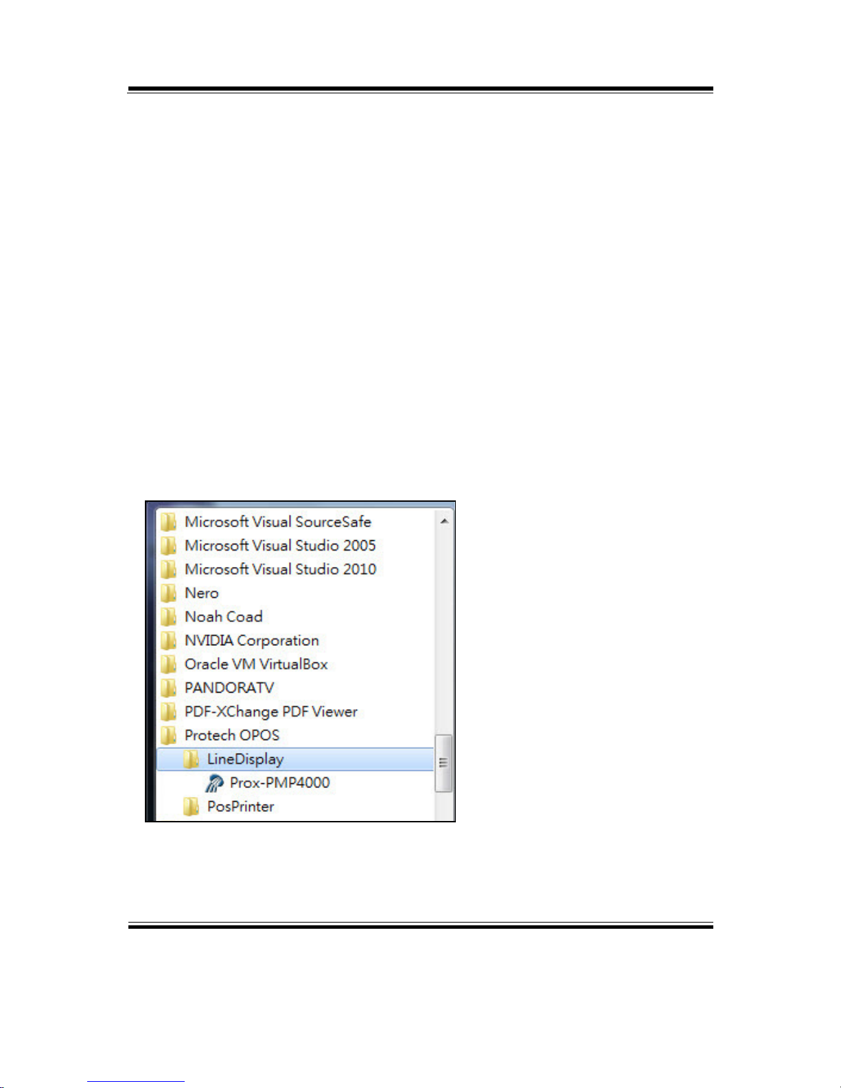
2. Launching Program
Below steps guide you to load the Prox-PMP4000 program.
Click LineDisplay folder from the path Start/Programs/Protech OPOS.
Click Prox-PMP4000 to launch the program.

Chapter 3 Software
PA-3122 SERIES USER′S MANUAL
Page:3-19
3. OPOS Control Object of Prox-PMP4000 program
Main screen buttons:
Button/Item Description
Text Display text at the current cursor position.
TextAt Display the string of characters at the specified “y ” and
“x ”.
Clear Clear the current window by displaying
Attribute Normal, blink, reverse, blink, reverse
4. MB4103 type
Key Name Type Default Value Note
BaudRate String
9600 UART Baud Rate (default)
BitLength String
8 UART Data Bit (default)
Parity String
0 UART Parity Bit (default)
Port String
COM1 UART Port (default)
Stop String
1 UART Stop Bit (default)

Chapter 3 Software
PA-3122 SERIES USER′S MANUAL
Page:3-20
5. OPOS APIs Support List
Category
Type
Name Mutability OPOS
APG
Version
VFD .SO
Properties common bool AutoDisable R/W 1.2 Not Applicable
Properties common long BinaryConversion R/W 1.2 Not Applicable
Properties common long CapPowerReporting Read only 1.3 Not Applicable
Properties common
string
CheckHealthText Read only 1.0 Supported
Properties common bool Claimed Read only 1.0 Supported
Properties common long DataCount Read only 1.2 Not Applicable
Properties common bool DataEventEnabled Read only 1.0 Not Applicable
Properties common bool DeviceEnabled R/W 1.0 Not Applicable
Properties common bool FreezeEvents R/W 1.0 Not Applicable
Properties common long OpenResult Read only 1.5 Not Applicable
Properties common bool OutputID Read only 1.0 Not Applicable
Properties common bool PowerNotify R/W 1.3 Not Applicable
Properties common bool PowerState Read only 1.3 Not Applicable
Properties common long ResultCode Read only 1.0 Supported
Properties common long ResultCodeExtended Read only 1.0 Not Applicable
Properties common long State Read only 1.0 Supported
Properties common
string
ControlObject
Description
Read only 1.0 Not Applicable
Properties common long ControlObject Version Read only 1.0 Not Applicable
Properties common
string
ServiceObject
Description
Read only 1.0 Supported
Properties common long ServiceObject Version Read only 1.0 Supported
Properties common
string
DeviceDescription Read only 1.0 Supported
Properties common
string
ControlObject
Description
Read only 1.0 Not Applicable
Properties specific long CapBlink Read only 1.0 Not Applicable
Properties specific bool CapBlinkRate Read only 1.6 Not Applicable
Properties specific bool CapBrightness Read only 1.0 Not Applicable
Properties specific long CapCharacterSet Read only 1.0 Not Applicable
Properties specific long CapCursorType Read only 1.6 Not Applicable
Properties specific bool CapCustomGlyph Read only 1.6 Not Applicable
Properties specific bool CapDescriptors Read only 1.0 Not Applicable
Properties specific bool CapHMarquee Read only 1.0 Not Applicable

Chapter 3 Software
PA-3122 SERIES USER′S MANUAL
Page:3-21
Category
Type
Name Mutability OPOS
APG
Version
VFD .SO
Properties specific bool CapICharWait Read only 1.0 Not Applicable
Properties specific long CapReadBack Read only 1.6 Not Applicable
Properties specific long CapReverse Read only 1.6 Not Applicable
Properties specific bool CapVMarquee Read only 1.0 Not Applicable
Properties specific long BlinkRate R/W 1.6 Not Applicable
Properties specific long DeviceWindows Read only 1.0 Not Applicable
Properties specific long DeviceRows Read only 1.0 Not Applicable
Properties specific long DeviceColumns Read only 1.0 Not Applicable
Properties specific long DeviceDescriptors Read only 1.0 Not Applicable
Properties specific long DeviceBrightness R/W 1.0 Not Applicable
Properties specific long CharacterSet R/W 1.0 Not Applicable
Properties specific string CharacterSetList Read only 1.0 Not Applicable
Properties specific long CurrentWindow R/W 1.0 Not Applicable
Properties specific long Rows Read only 1.0 Not Applicable
Properties specific long Columns Read only 1.0 Not Applicable
Properties specific long CursorRow R/W 1.0 Not Applicable
Properties specific long CursorColumn R/W 1.0 Not Applicable
Properties specific long CursorType R/W 1.6 Not Applicable
Properties specific bool CursorUpdate R/W 1.0 Not Applicable
Properties specific long MarqueeType R/W 1.0 Not Applicable
Properties specific long MarqueeFormat R/W 1.0 Not Applicable
Properties specific long MarqueeUnitWait R/W 1.0 Not Applicable
Properties specific long MarqueeRepeatWait R/W 1.0 Not Applicable
Properties specific long InterCharacterWait R/W 1.0 Not Applicable
Properties specific string CustomGlyphList Read only 1.6 Not Applicable
Properties specific long GlyphHeight Read only 1.6 Not Applicable
Properties specific long GlyphWidth Read only 1.6 Not Applicable
Methods common Open
-
1.0 Supported
Methods common Close
-
1.0 Supported
Methods common Claim
-
1.0 Supported
Methods common ClaimDevice
-
1.0 Supported
Methods common Release
-
1.0 Supported
Methods common ReleaseDevice
-
1.0 Supported
Methods common CheckHealth
-
1.0 Not Applicable
Methods common ClearInput
-
1.0 Not Applicable
Methods common ClearOutput
-
1.0 Not Applicable

Chapter 3 Software
PA-3122 SERIES USER′S MANUAL
Page:3-22
Category
Type
Name Mutability OPOS
APG
Version
VFD .SO
Methods common DirectIO
-
1.0 Not Applicable
Methods specific DisplayText
-
1.0 Supported
Methods specific DisplayTextAt
-
1.0 Supported
Methods specific ClearText
-
1.0 Supported
Methods specific ScrollText
-
1.0 Not Applicable
Methods specific SetDescriptor
-
1.0 Not Applicable
Methods specific ClearDescriptors
-
1.0 Not Applicable
Methods specific CreateWindow
-
1.0 Not Applicable
Methods specific DestroyWindow
-
1.0 Not Applicable
Methods specific RefreshWindow
-
1.0 Not Applicable)
Methods specific ReadCharacterAtCursor
-
1.6 Not Applicable
Methods specific DefineGlyph
-
1.6 Not Applicable
Events common DataEvent
-
1.0 Not Applicable
Events common DirectIOEvent
-
1.0 Not Applicable
Events common ErrorEvent
-
1.0 Not Applicable
Events common OutputComplete
Event
-
1.0 Not Applicable
Events common StatusUpdate
Event
-
1.3 Not Applicable

Chapter 3 Software
PA-3122 SERIES USER′S MANUAL
Page:3-23
3-2-3. MSR: MB-3012 (PS/2)
3-2-3-1. OPOS Driver
The MB301X_OposSetup.exe program sets up the registry information of MSR
reader for OPOS program uses.
1. Installation
Below steps guide you to install the MB301X_OposSetup program.
Run the OPOSMSR_Setup.exe setup file.
This setup also installs the Prox-PMP3000 program.
Follow the wizard instructions to complete the installation.
2. Launching Program
Below steps guide you load the Prox-PMP3000 program.
Click MSR folder from the path Start/Programs/Protech OPOS.
Click Prox-PMP3000 to launch the program.

Chapter 3 Software
PA-3122 SERIES USER′S MANUAL
Page:3-24
3. Configuration of Prox-PMP3000 program
a.) Main screen & Control tab items:
Button/Item Description
COM (dropdown list) To set COM port number (only for
USRT/USB interface).
AutoDisable (check box) Set auto-disable
FreeseEvents (check box) Set freeze events

Chapter 3 Software
PA-3122 SERIES USER′S MANUAL
Page:3-25
b.) Description tab: S.O and C.O information
c.) Track Control tab items
Button/Item Description
DecodeData Set decode data properties applicable).
ParseDecodeData Set parse decode data properties
TransmitSentinels Set transmit-sentinels properties
ErrorReporting Type Card, track
TracksToRead Track1, track2, track3, tracks12, tracks13, tracks14,
tracks23, tracks24, tracks34, tracks123, tracks124,
tracks134, tracks234, tracks1234 (Tracks4 is not
applicable).

Chapter 3 Software
PA-3122 SERIES USER′S MANUAL
Page:3-26
d.) Track Data tab items
Button/Item Description
TracksData (Row) Display data of all tracks (Track4 is not applicable).
e.) Parsed Data tab items
Button/Item Description
Parsed Data Display special properties.

Chapter 3 Software
PA-3122 SERIES USER′S MANUAL
Page:3-27
4. MB301X type (RS232/PS2)
Key Name Type Default Value Note
default string PMP3000 OPOS S.O Link
5. OPOS APIs support List
Category
Type
Name Mutability OPOS
APG
Version
VFD .SO
Properties
common bool
AutoDisable R/W 1.2 Supported
Properties
common long
BinaryConversion R/W 1.2 Not Applicable
Properties
common long
CapPowerReporting Read only 1.3 Supported
Properties common
string
CheckHealthText Read only 1.0 Supported
Properties common bool Claimed Read only 1.0 Supported
Properties common long DataCount Read only 1.2 Supported
Properties common bool DataEventEnabled R/W 1.0 Supported
Properties common bool DeviceEnabled R/W 1.0 Supported
Properties common bool FreezeEvents R/W 1.0 Supported
Properties common long OpenResult Read only 1.5 Supported
Properties common long OutputID Read only 1.0 Not Applicable
Properties common long PowerNotify R/W 1.3 Not Applicable
Properties common long PowerState Read only 1.3 Not Applicable
Properties common long ResultCode Read only 1.0 Supported
Properties common long ResultCodeExtended Read only 1.0 Supported
Properties common long State Read only 1.0 Not Applicable
Properties common
string
ControlObject
Description
Read only 1.0 Not Applicable
Properties common long ControlObjectVersion Read only 1.0 Not Applicable
Properties common
string
ServiceObject
Description
Read only 1.0 Supported
Properties common long ServiceObjectVersion Read only 1.0 Not Applicable
Properties common
string
DeviceDescription Read only 1.0 Supported
Properties common string DeviceName Read only 1.0 Supported
Properties specific bool CapISO Read only 1.0 Supported
Properties specific bool CapJISOne Read only 1.0 Supported
Properties specific bool CapJISTwo Read only 1.0 Supported
Properties specific bool CapTransmitSentinels Read only 1.5 Supported

Chapter 3 Software
PA-3122 SERIES USER′S MANUAL
Page:3-28
Category
Type
Name Mutability OPOS
APG
Version
VFD .SO
Properties specific long TracksToRead R/W 1.0 Supported
Properties specific bool DecodeData R/W 1.0 Not Applicable
Properties specific bool ParseDecodeData R/W 1.0 Supported
Properties specific long ErrorReportType R/W 1.2 Not Applicable
Properties s
pecific string
Track1Data Read only 1.0 Supported
Properties s
pecific string
Track2Data Read only 1.0 Supported
Properties s
pecific string
Track3Data Read only 1.0 Supported
Properties s
pecific string
Track4Data Read only 1.5 Not Applicable
Properties s
pecific string
AccountNumber Read only 1.0 Supported
Properties s
pecific string
ExpirationDate Read only 1.0 Supported
Properties s
pecific string
Title Read only 1.0 Supported
Properties s
pecific string
FirstName Read only 1.0 Supported
Properties s
pecific string
MiddleInitial Read only 1.0 Supported
Properties s
pecific string
Surname Read only 1.0 Supported
Properties s
pecific string
Suffix Read only 1.0 Supported
Properties s
pecific string
ServiceCode Read only 1.0 Supported
Properties specific
binary
Track1
DiscretionaryData
Read only 1.0 Supported
Properties specific
binary
Track2
DiscretionaryData
Read only 1.0 Supported
Properties specific bool TransmitSentinels R/W 1.5 Supported
Methods common Open
-
1.0 Supported
Methods common Close
-
1.0 Supported
Methods common Claim
-
1.0 Supported
Methods common ClaimDevice
-
1.5 Supported
Methods common Release
-
1.0 Supported
Methods common ReleaseDevice
-
1.5 Supported
Methods common CheckHealth
-
1.0 Not Applicable
Methods common ClearInput
-
1.0 Supported
Methods common ClearOutput
-
1.0 Not Applicable
Methods common DirectIO
-
1.0 Not Applicable
Events common DataEvent
-
1.0 Supported
Events common DirectIOEvent
-
1.0 Not Applicable
Events common ErrorEvent
-
1.0 Not Applicable
Events common OutputCompleteEvent
-
1.0 Not Applicable
Events common StatusUpdateEvent
-
1.0 Not Applicable

Chapter 3 Software
PA-3122 SERIES USER′S MANUAL
Page:3-29
3-2-4. MSR: GIGA-TMS MJR243R (RS-232)
3-2-4-1. Command List
1. MSR Registry Operation
Registry Path: [HKEY_LOCAL_MACHINE\SOFTWARE\OLEforRetail\ServiceOPOS\
MSR\MJR243]
Registry Name Default Data Notes
CapISO 1 Capability for reading
ISO track data
CapJISOne 1 (reserved)
CapJISTwo 1 (reserved)
CapTransmitSentinels 1 Capability for reading
Transmit Sentinels
Debug 0 Enable the tracing,
and create a log file
Description GIGATMS
MSR POS
Description for SO driver
DeviceName MJR243 Devive Name for CO open
FileName (NULL) (reserved)
HardwareProvider 0 (reserved)
Model MJR243 Device model name
Parity None Parity for the communication
port
Port COM4 Comport
Protocol Hardware Communication Control
Baudrate 19200 RS232 baudrate

Chapter 3 Software
PA-3122 SERIES USER′S MANUAL
Page:3-30
2. OPOS MSR Service Object and Method Relations
Method Status of support by
the driver
Notes
Open ○ Close ○ Claim ○ ClaimDevice ○ Release ○ ReleaseDevice ○ ClearInput ○ ClearInputProperties ○ DataEvent ○ Claimed ○ Read only
DataCount ○ Read only
DataEventEnabled ○ R/W
DeviceEnabled ○ R/W
FreezeEvents ○ R/W
OpenResult ○ Read only
ResultCode ○ Read only
ResultCodeExtended ○ Read only
State ○ Read only
ControlObjectDescription ○ Read only
ControlObjectVersion ○ Read only
ServiceObjectDescription ○ Read only
ServiceObjectVersion ○ Read only
DeviceDescription ○ Read only
DeviceName ○ Read only
CapISO ○ Read only
CapTransmitSentinels ○ Read only
AccountNumber ○ Read only
DecodeData ○ R/W
ExpirationDate ○ Read only
FirstName ○ Read only
MiddleInitial ○ Read Only
ParseDecodeData ○ R/W

Chapter 3 Software
PA-3122 SERIES USER′S MANUAL
Page:3-31
Method Status of support by
the driver
Notes
ServiceCode ○ Read Only
Suffix ○ Read Only
Surname ○ Read Only
Title ○ Read Only
Track1Data ○ Read Only
Track1DiscretionaryData ○ Read Only
Track2Data ○ Read Only
Track2DiscretionaryData ○ Read Only
Track3Data ○ Read Only
TracksToRead ○ R/W
TransmitSentinels ○ R/W

Chapter 3 Software
PA-3122 SERIES USER′S MANUAL
Page:3-32
3-2-4-2. OPOS MSR Register
The OPOS MSR Register program sets up the registry information of MSRHK
reader for OPOS program uses.
1. Installation
Below steps guide you to install the OPOS MSR Register program.
Insert the setup CD
Run the setup file OPOSMSR_Setup.exe located in the Software folder of CD.
This setup also installs the OPOS MSR Tester program.
Follow the wizard instructions to complete the installation.
2. Launching Program
Below steps guide you to load the OPOS MSR Register program.
Click OPOS folder from the path Start/Programs/GIGA‐TMS.
Click OPOS MSR Register to launch the program.

Chapter 3 Software
PA-3122 SERIES USER′S MANUAL
Page:3-33
3. Configuration of OPOS MSR Register program
a.) Main screen buttons/items:
Button/Item Description
Control Object (Check box) Register the OPOSMSR.ocx common
control object driver. This needs to be checked to run the
OPOS MSR Tester program.
Service Object (Left pane) The Service Object driver types. So far only
four types are supported. Each type support specific MSR
readers. For more details, please refer to the section
OPOS MSR Service Object and Method Relations.
Service Object (Right pane) The registered MSR with specified device
name.
Reg Create a new device name for selected MSR.
Unreg Remove selected device name from registry.
Exit End the program.
b.) Follow the steps below to register the MSRHK OPOS information.
Step 1: Select an item in Service Object List box (left pane). Make sure the
correct item is selected.
Step 2: Click Reg button
Step 3: In the OPOS MSR Setting screen, enter the device name and click OK.

Chapter 3 Software
PA-3122 SERIES USER′S MANUAL
Page:3-34
c.) Example 1. MAGTEK USB HID
d.) Example 2. PROMAG MSR/MJR PART NO, Keyboard mode.‐

Chapter 3 Software
PA-3122 SERIES USER′S MANUAL
Page:3-35
e.) Example 3. PROGRAM MSR PART NO, HID mode.
‐
If your system doesn’t have any other common control driver, then click Control
Object check box.
Note: To run the OPOPS MSR Tester program, the Control Object must be checked.
4. MJR243 type
Key Name Type Default Value Note
CapISO string 1 Capability for reading ISO
track data
CapJISOne string 1 (reserved)
CapJISTwo string 1 (reserved)
CapTransmitSentinels string 1 Capability for reading
Transmit Sentinels
Debug string 0 Enable the tracing, and create a
log file
Description string GIGATMS
MSR POS
Description for SO driver
DeviceName string MJR243 Devive Name for CO open
FileName string (NULL) (reserved)

Chapter 3 Software
PA-3122 SERIES USER′S MANUAL
Page:3-36
Key Name Type Default Value Note
HardwareProvider string 0 (reserved)
Model string MJR243 Device model name
Parity string None Parity for the communication port
Port string COM4 Comport Number
Protocol string Hardware Communication Control
Baudrate string 19200 RS232 baudrate
5. OPOS APIs support list
Category
Type
Name Mutability OPOS
APG
Version
MSR .SO
Properties common bool AutoDisable R/W 1.2 Not Applicable
Properties common long BinaryConversion R/W 1.2 Not Applicable
Properties common bool CapCompare
FirmwareVersion
Read only 1.9 Not Applicable
Properties common long CapPowerReporting Read only 1.3 Not Applicable
Properties common bool CapStatisticsReporting Read only 1.8 Not Applicable
Properties common bool CapUpdateFirmware Read only 1.9 Not Applicable
Properties common bool CapUpdateStatistics Read only 1.8 Not Applicable
Properties common
string
CheckHealthText Read only 1.0 Not Applicable
Properties common bool Claimed Read only 1.0 Supported
Properties common long DataCount Read only 1.2 Supported
Properties common bool DataEventEnabled R/W 1.0 Supported
Properties common bool DeviceEnabled R/W 1.0 Supported
Properties common bool FreezeEvents R/W 1.0 Supported
Properties common long OpenResult Read only 1.5 Supported
Properties common long OutputID Read only 1.0 Not Applicable
Properties common long PowerNotify R/W 1.3 Not Applicable
Properties common long PowerState Read only 1.3 Not Applicable
Properties common long ResultCode Read only 1.0 Supported
Properties common long ResultCodeExtended Read only 1.0 Supported
Properties common long State Read only 1.0 Supported
Properties common
string
ControlObject
Description
Read only 1.0 Supported
Properties common long ControlObjectVersion Read only 1.0 Supported
Properties common ServiceObject Read only 1.0 Supported

Chapter 3 Software
PA-3122 SERIES USER′S MANUAL
Page:3-37
Category
Type
Name Mutability OPOS
APG
Version
MSR .SO
string Description
Properties common long ServiceObjectVersion Read only 1.0 Supported
Properties common
string
DeviceDescription Read only 1.0 Supported
Properties common
string
DeviceName Read only 1.0 Supported
Properties specific bool CapISO Read only 1.0 Supported
Properties specific bool CapJISOne Read only 1.0 Not Applicable
Properties specific bool CapJISTwo Read only 1.0 Not Applicable
Properties specific bool CapTransmit
Sentinels
Read only 1.5 Supported
Properties specific long CapWriteTracks Read only 1.1 Not Applicable
Properties s
pecific string
AccountNumber Read only 1.0 Supported
Properties specific bool DecodeData R/W 1.0 Supported
Properties specific long EncodingMaxLength Read only 1.1 Not Applicable
Properties specific long ErrorReportType R/W 1.2 Not Applicable
Properties s
pecific string
ExpirationDate Read only 1.0 Supported
Properties s
pecific string
FirstName Read only 1.0 Supported
Properties s
pecific string
MiddleInitial Read only 1.0 Supported
Properties specific bool ParseDecodeData R/W 1.0 Supported
Properties s
pecific string
ServiceCode Read only 1.0 Supported
Properties s
pecific string
Suffix Read only 1.0 Supported
Properties s
pecific string
Surname Read only 1.0 Supported
Properties s
pecific string
Title Read only 1.0 Supported
Properties specific
binary
Track1Data Read only 1.0 Supported
Properties specific
binary
Track1
DiscretionaryData
Read only 1.0 Supported
Properties specific
binary
Track2Data Read only 1.0 Supported
Properties specific
binary
Track2
DiscretionaryData
- 1.0 Supported
Properties specific
binary
Track3Data Read only 1.0 Supported
Properties specific
binary
Track4Data Read only 1.5 Not Applicable
Properties specific long TracksToRead R/W 1 Supported

Chapter 3 Software
PA-3122 SERIES USER′S MANUAL
Page:3-38
Category
Type
Name Mutability OPOS
APG
Version
MSR .SO
Properties specific long TracksToWrite R/W 1.1 Not Applicable
Properties specific bool TransmitSentinels R/W 1.5 Supported
Methods common Open - 1 Supported
Methods common Close - 1 Supported
Methods common Claim - 1 Supported
Methods common ClaimDevice - 1.5 Supported
Methods common Release - 1 Supported
Methods common ReleaseDevice - 1.5 Supported
Methods common CheckHealth - 1 Not Applicable
Methods common ClearInput - 1 Supported
Methods common ClearInput
Properties
- 1.1 Supported
Methods common ClearOutput - 1 Not Applicable
Methods common DirectIO - 1 Not Applicable
Methods common Compare
FirmwareVersion
- 1.9 Not Applicable
Methods common ResetStatistics - 1.8 Not Applicable
Methods common RetrieveStatistics - 1.8 Not Applicable
Methods common UpdateFirmware - 1.9 Not Applicable
Methods common UpdateStatistics - 1.8 Not Applicable
Events common DataEvent - 1.0 Supported
Events common DirectIOEvent - 1.0 Not Applicable
Events common ErrorEvent - 1.0 Not Applicable
Events common OutputCompleteEvent - 1.0 Not Applicable
Events common StatusUpdateEvent - 1.0 Not Applicable

Chapter 3 Software
PA-3122 SERIES USER′S MANUAL
Page:3-39
3-2-4-3. OPOS MSR Tester
The OPOS MSR Tester program is used to get the track data of MSRHK reader via
the OPOS driver. Before running the program, make sure the device name registry
information for MSRHK reader has been already created by OPOS MSR Register
program.
1. Installation
The installation of OPOS MSR Tester program goes together with OPOS MSR
Register program.
2. Launching Program
Below steps guide you to load the OPOS MSR Tester program.
Click OPOS folder from the path Start\Programs\GIGA‐TMS.
Click OPOS MSR Tester to launch the program.

Chapter 3 Software
PA-3122 SERIES USER′S MANUAL
Page:3-40
3. Configuration for OPOS MSR Tester Program
a.) Main screen buttons/items:
Button/Item Description
Device Name (Combo box) Enter the device name that to be loaded to
the program.
Track Data (Text boxes) Show the raw and parsed track data.
Clear (Button) Clear all the track data in the text boxes.
Open: (Button) Open the OPOS driver and ready to get
track data.
Close (Button) Close the OPOS driver.
Message (Text box) Display the result message of running the
OPOS driver.
b.) To start using OPOS driver to get track data, follow the steps below.
Step 1: Entering the Device Name.
Step 2: Clicking Open button.
Step 3: Swiping card to get track data.

Chapter 3 Software
PA-3122 SERIES USER′S MANUAL
Page:3-41
c.) Example 1. MAGTEK USB HID.
d.) Example 2. PROMAG MSR/MJR PART NO, Keyboard mode‐
 Loading...