


USER’S
MANUAL
EB-591LF
Intel
®®®®
Queens Bay
3.5” Embedded Board
With LVDS/ Audio/ 2 LAN
EB-591LF
M1

Copyright Notice
EB-591LF Intel® Queens Bay
3.5” Embedded Board
With LVDS/ Audio/ 2LAN
COPYRIGHT NOTICE
All trademarks and registered trademarks mentioned herein are the property of their
respective owners.
This manual is copyrighted in July 2012. You may not reproduce or transmit in any
form or by any means, electronic, or mechanical, including photocopying and
recording.
DISCLAIMER
This operation manual is meant to assist both Embedded Computer manufacturers
and end users in installing and setting up the system. The information contained in
this document is subject to change without any notice.
CE NOTICE
This is a class A product. In a domestic environment this product may cause radio
interference in which case the user may be required to take adequate measures.

Copyright Notice
FCC NOTICE
This equipment has been tested and found to comply with the limits for a Class A
digital device, pursuant to part 15 of the FCC Rules. These limits are designed to
provide reasonable protection against harmful interference when the equipment is
operated in a commercial environment. This equipment generates, uses, and can
radiate radio frequency energy and, if not installed and used in accordance with
the instruction manual, may cause harmful interference to radio communications.
Operation of this equipment in a residential area is likely to cause harmful
interference in which case the user will be required to correct the interference at
his own expense.
You are cautioned that any change or modifications to the equipment not
expressly approve by the party responsible for compliance could void your
authority to operate such equipment.

Contents
TABLE OF CONTENTS
CHAPTER 1 INTRODUCTION
1-1 About This Manual…......................................................... 1-2
1-2 System Specification…....................................................... 1-3
1-3 Safety Precautions…........................................................... 1-5
CHAPTER 2 HARDWARE CONFIGURATION
2-1 Jumper & Connector Quick Reference Table…................. 2-2
2-2 Component Locations….…................................................ 2-3
2-3 How to Set the Jumpers….................................................. 2-7
2-4 COM Port Connector (Win XP & 7)…...……………….... 2-9
2-5 COM Port Connector (Win CE 6.0: Optional)….………... 2-10
2-6 COM Port RI & Voltage Selection (Win XP & 7).……… 2-11
2-7 COM Port RI & Voltage Selection (Win CE 6.0: Optional) 2-12
2-8 RS232/422/485 Selection (Win XP & 7)............................ 2-13
2-9 RS232/422/485 Selection(Win CE 6.0: Optional).............. 2-14
2-10 Auto RS485 Selection (Win XP & 7)................................. 2-15
2-11 Auto RS485 Selection (Win CE 6.0: Optional).................. 2-16
2-12 Universal Serial Bus Connector………………………….. 2-17
2-13 Audio Connector….……………….……………………… 2-18
2-14 System Fan Connector ……………................................ 2-18
2-15 Front Panel Connector ………………………………… 2-19
2-16 Power Connector .....................................................…… 2-19
2-17 HDD Power Connector .............................................….. 2-19
2-18 Digital Input/Output Connector ….…………….………. 2-20
2-19 SDIO Connector ……………………………………….. 2-20
2-20 SDVO Connector ............................................................ 2-21
2-21 LVDS Connector ............................................................ 2-22
2-22 LVDS Voltage Selection …............................................. 2-23
2-23 LVDS Power Connector …............................................. 2-23
2-24 AT/ATX Power Selection ……………………………... 2-24
2-25 Serial ATA Connector …………………..…………….. 2-24
2-26 LAN Connector …………………..……………………. 2-25
2-27 LPC Connector ………………………………………… 2-27
2-28 CAN Bus Connector …………………………………… 2-27
2-29 Load Default Selection ………………………………… 2-28

Contents
CHAPTER 3 SOFTWARE UTILITIES
3-1 Introduction …………..........................................…....... 3-2
3-2 Intel Chipset Software Installation Utility …..……..…... 3-3
3-3 VGA Driver Utility ……………………………….……. 3-4
3-4 LAN Driver Utility …...........................................…....... 3-5
3-5 Sound Driver Utility …………………………………… 3-6
3-6 RS232 Driver Utility …………………………………... 3-7
CHAPTER 4 AMI BIOS SETUP
4-1 Introduction ..................................................................... 4-2
4-2 Entering Setup ................................................................. 4-4
4-3 Main ……….................................................................... 4-6
4-4 Advanced ........................................................................ 4-9
4-5 Chipset ............................................................................ 4-18
4-6 Boot …............................................................................ 4-29
4-7 Security ........................................................................... 4-32
4-8 Save & Exit ..................................................................... 4-33
APPENDIX A EXPANSION BUS
Mini PCI-E Connector Pin Assignment ……………………….. A-2
APPENDIX B TECHNICAL SUMMARY
Block Diagram ........................................................................... B-2
Interrupt Map ............................................................................. B-3
DMA Channels Map .................................................................. B-5
I/O Map ..................................................................................... B-6
Watchdog Timer Configuration ………………...…………….. B-10
Flash BIOS Update ..............................................….................. B-12

Page:1-1
INTRODUCTION
This chapter gives you the information for EB-591LF. It also
outlines the system specifications.
Sections included:
About This Manual
System Specifications
Safety Precautions
Experienced users can jump to chapter 2 on page 2-1
for a quick start.
CHAPTER
1

Chapter 1 Introduction
Page: 1-2
EB-591LF USER′S MANUAL
1-1. ABOUT THIS MANUAL
Thank you for purchasing our EB-591LF Intel® Queens Bay 3.5” Embedded
Board enhanced with LVDS/Audio/2LAN, which is fully PC / AT compatible. The
EB-591LF provides faster processing speed, greater expandability and can handle
more tasks than before. This manual is designed to assist you how to install and set
up the system. It contains four chapters. The user can apply this manual for
configuration according to the following chapters:
Chapter 1 Introduction
This chapter introduces you to the background of this manual, and the
specifications for this system. The final page of this chapter will indicate how to
avoid damaging this board.
Chapter 2 Hardware Configuration
This chapter outlines the component locations and their functions. In the end of
this chapter, you will learn how to set jumper and how to configure this card to
meet your own needs.
Chapter 3 Software Utilities
This chapter contains helpful information for proper installations of the VGA
utility, LAN utility, Sound utility, and Flash BIOS Update. It also describes the
Watchdog-timer configuration.
Chapter 4 Award BIOS Setup
This chapter indicates you how to set up the BIOS configurations.
Appendix A Expansion Bus
This appendix introduces you the expansion bus for PCI-104 connector.
Appendix B Technical Summary
This appendix gives you the information about the Technical maps.

Chapter 1 Introduction
EB-591LF USER′S MANUAL
Page: 1-3
1-2. SYSTEM SPECIFICATIONS
System
CPU Support Intel® Atom E6XX processors (Tunnel Creek, Queens Bay
platform)
Chipset Intel® EG20T PCH (Topcliff, Queens Bay platform)
Memory DDR2 on board, supports 800MHz up to 2GB
Power Supply AT/ATX mode, DC 12V only
OS Windows XP, Windows 7, DOS
BIOS AMI uEFI BIOS
Watchdog 1~255 sec. via Tunnel Creek
Dimension 3.5” Size (102mm x 145mm)
Certificate FCC/CE
I/O Ports
Serial Port 4 ports:
COM4/5/6 for 3 x RS-232, COM3 for RS-232/422/485
Not support power on by ring (chipset limitation)
USB 4 x USB 2.0 ports
1 x mini USB
SATA Interface 1 x S-ATA port
MMC/SD 1 x Micro-SD flash connector
1 x SDIO
LAN Dual Ports
Lan 1/2 : Giga LAN;
supports Wake-on-LAN
Audio High Definition Audio; supports Line-in, Line-out, Mic
Digital I/O 4-in/4-out
Expansion Function Mini-PCIe Half-size platform, SD singal connector, LPC
Display
Graphics Build-in Tunnel Creek; supports LVDS (24bits single
channel) & SDVO

Chapter 1 Introduction
Page: 1-4
EB-591LF USER′S MANUAL
Environment
Operation
Temperature
General: 0 ~ 60°C (32 ~ 140°F)
WDT: -40 ~ 85°C (-40 ~ 185°F)
Storage Temperature -40 ~ 85°C (-40 ~ 185°F)
Humidity Operation: 10 ~ 90%
Storage: 5 ~ 95%

Chapter 1 Introduction
EB-591LF USER′S MANUAL
Page: 1-5
1-3. SAFETY PRECAUTIONS
Follow the messages below to avoid your systems from damage:
1. Keep your system away from static electricity on all occasions.
2. Prevent electric shock. Don‘t touch any components of this card when the card is
power-on. Always disconnect power when the system is not in use.
3. Disconnect power when you change any hardware devices.
For instance, when you connect a jumper or install any cards, a surge of power
may damage the electronic components or the whole system.

Page 2-1
HARDWARE
CONFIGURATION
** QUICK START **
CHAPTER
2
Helpful information describes the jumper & connector settings, and
component locations.
Sections included:
Jumper & Connector Quick Reference Table
Component Locations
Configuration and Jumper settings
Connector’s Pin Assignments

Chapter 2 Hardware Configuration
Page: 2-2
EB-591LF USER′S MANUAL
2-1. JUMPER & CONNECTOR QUICK REFERENCE TABLE
JUMPER / CONNECTOR NAME
COM Port Connector COM3, COM3_1 (Optional), J6
COM3 Port RI/Voltage Selection JP9
RS232/422/485 (COM3) Selection JP6
Auto RS485 (COM3) Selection JP5
Universal Serial Bus Connector USB1, USB2, USBD1
Audio Connector AUDIO1
System Fan Connector FAN1
Front Panel Connector FP1
Power Connector POWER_IN1
HDD Power Connector HDD_POWER1
Digital Input/Output Connector J5
SDIO Connector SDIO1
SDVO Connector SDVO1
LVDS Connector LVDS1
LVDS Voltage Selection JP2
LVDS Power Connector INV1
AT/ATX Power Selection JP8
Serial ATA Connector SATA1
LAN Connector LAN1, LAN2
LPC Connector LPC1
CAN Bus Connector CAN1
Load Default Selection JP10
Mini PCI-E M_PCIE1

Chapter 2 Hardware Configuration
EB-591LF USER′S MANUAL
Page: 2-3
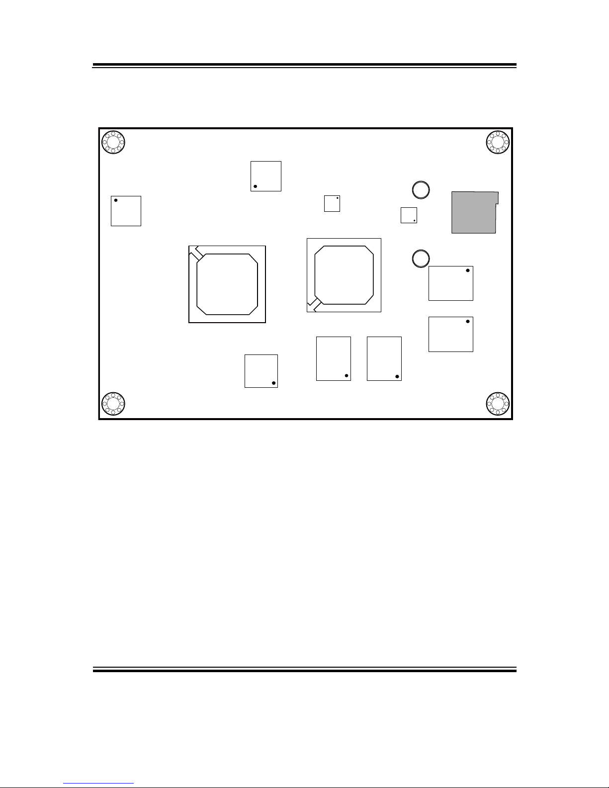
2-2. COMPONENT LOCATIONS (I)
2-2-1 With Dual LANs
14
58
1
9
2
10
11
12
13
14
1
9
2
10
11
12
13
14
1 2
109
1
6273849
5
1
2
29
30 1
6
41
1426
113
31
1
7
12
1112
2
71
1
1
M_PCIE1
1 2
15 16
17 18
51 52
15
12
1
FAN1
SP1
JP8
1
USB1 USBD1
1
JP5
JP9 JP6
LPC1
1
2
125
6 10
9
1
220
19
1 11
2 12
J4
1
2
6
5
1
JP10
JP2
LVDS1
SATA1
HDD_POWER1
INV1
SDVO1
POWER_IN1
J5
CAN1
SDIO1
LAN1
LAN2
J6
1
2
9
10
1
2
9
10
USB2 AUDIO1
FP1
COM3
1
5
Memory
Memory
Memory
Memory
Battery
COM3_1
EB-591LF Front Connector, Jumper and Component locations

Chapter 2 Hardware Configuration
Page: 2-4
EB-591LF USER′S MANUAL
Memory
MemoryMemory
Memory
Audio
PMIC
LAN
LAN
Intel Topcliff
Intel
Tunnel Creek
MICRO_SD_CARD1
EB-591LF Rear Connector, Jumper and Component locations

Chapter 2 Hardware Configuration
EB-591LF USER′S MANUAL
Page: 2-5
2-2-2 With One LAN
14
58
1
9
2
10
11
12
13
14
1 2
109
1
6273849
5
1
2
29
30 1
6
41
1426
113
31
1
7
12
1112
2
71
1
1
M_PCIE1
1 2
15 16
17 18
51 52
15
12
1
FAN1
SP1
JP8
1
USB1 USBD1
1
JP5
JP9 JP6
LPC1
1
2
125
6 10
9
1
220
19
1 11
2 12
J4
1
2
6
5
1
JP10
JP2
LVDS1
SATA1
HDD_POWER1
INV1
SDVO1
POWER_IN1
J5
CAN1
SDIO1
LAN1
J6
1
2
9
10
1
2
9
10
USB2 AUDIO1
FP1
COM3
1
5
Memory
Memory
Memory
Memory
Battery
COM3_1
EB-591LF Front Connector, Jumper and Component locations
Chapter 2 Hardware Configuration
Page: 2-6
EB-591LF USER′S MANUAL
Memory
MemoryMemory
Memory
Audio
PMIC
LAN
Intel Topcliff
Intel
Tunnel Creek
MICRO_SD_CARD1
EB-591LF Rear Connector, Jumper and Component locations

Chapter 2 Hardware Configuration
EB-591LF USER′S MANUAL
Page: 2-7
2-3. HOW TO SET THE JUMPERS
You can configure your board by setting jumpers. Jumper is consists of two or
three metal pins with a plastic base mounted on the card, and by using a small
plastic "cap", Also known as the jumper cap (with a metal contact inside), you
are able to connect the pins. So you can set-up your hardware configuration by
"open" or "close" pins.
The jumper can be combined into sets that called jumper blocks. When the
jumpers are all in the block, you have to put them together to set up the hardware
configuration. The figure below shows how this looks like.
JUMPERS AND CAPS
If a jumper has three pins (for examples, labelled PIN1, PIN2, and PIN3), You
can connect PIN1 & PIN2 to create one setting by shorting. You can either
connect PIN2 & PIN3 to create another setting. The same jumper diagrams are
applied all through this manual. The figure below shows what the manual
diagrams look and what they represent.

Chapter 2 Hardware Configuration
Page: 2-8
EB-591LF USER′S MANUAL
JUMPER DIAGRAMS
2 pin Jumper
looks like this
Jumper Cap
looks like this
3 pin Jumper
looks like this
Jumper Block
looks like this
JUMPER SETTINGS
Looks like this
3 pin Jumper
2-3 pin close(enabled)
Looks like this
Jumper Block
1-2 pin close(enabled)
2 pin Jumper close(enabled)
1
1
1
2
1 2
1
1
Looks like this
Chapter 2 Hardware Configuration
EB-591LF USER′S MANUAL
Page: 2-9
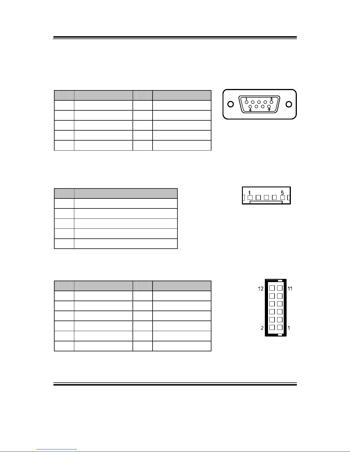
2-4. COM PORT CONNECTOR (WIN XP & 7)
COM3: COM3 Connector
The pin assignments are as follows:
PIN ASSIGNMENT PIN ASSIGNMENT
1 DCD3 6 DSR3
2 RXD3 7 RTS3
3 TXD3 8 CTS3
4 DTR3 9 RI3
5 GND
COM3_1: COM3_1 Connector
The pin assignments are as follows:
PIN ASSIGNMENT
1 GND
2 COM3_RX_R
3 COM3_TX_R
4 COM3_RTS_R
5 COM3_CTS_R
J6: COM4/5/6 Connector
The pin assignments are as follows:
PIN ASSIGNMENT PIN ASSIGNMENT
1 VCC12 7 COM5_RXD_R
2 VCC5 8 COM5_TXD_R
3 GND 9 COM6_RXD_R
4 GND 10 COM6_TXD_R
5 COM4_RXD_R 11 GND
6 COM4_TXD_R 12 NC
COM3
1
5
6 9
COM3_1
J6
Chapter 2 Hardware Configuration
Page: 2-10
EB-591LF USER′S MANUAL
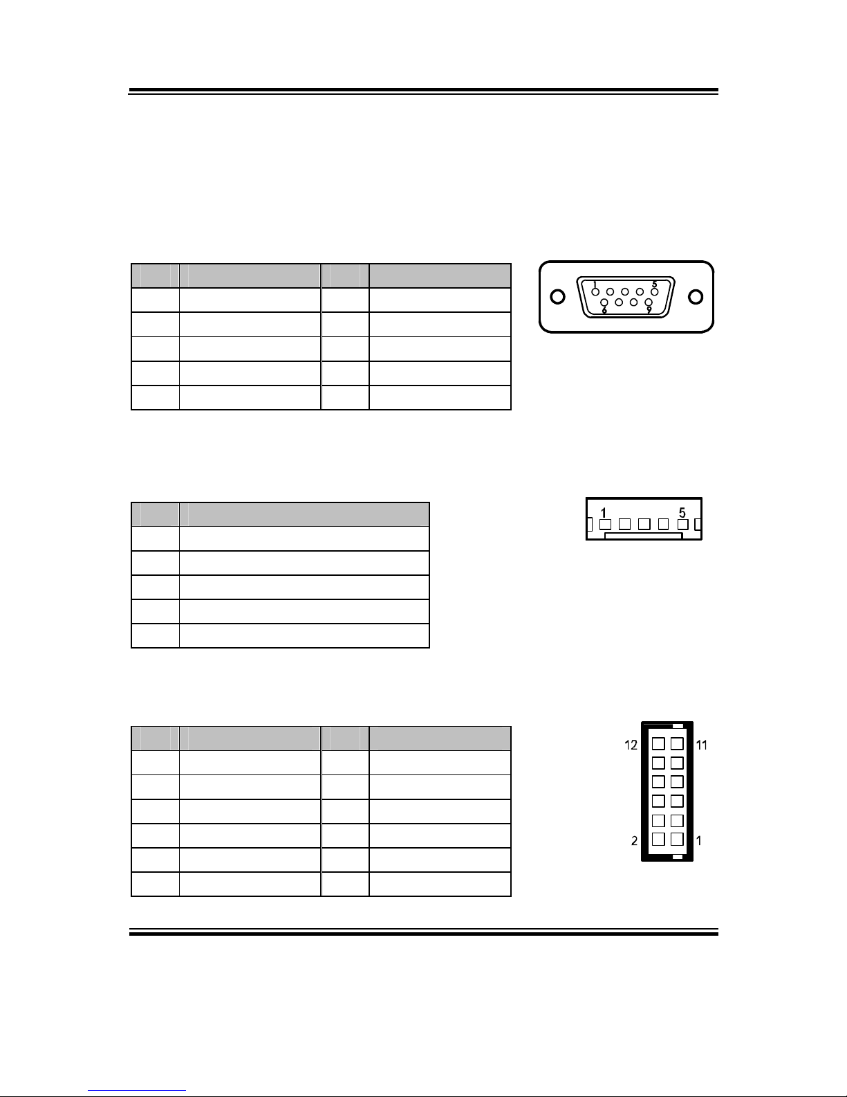
2-5. COM PORT CONNECTOR (WIN CE 6.0: OPTIONAL)
Caution: COM3 will be assigned as COM4 in Win CE 6.0.
COM4: COM3 Connector
The pin assignments are as follows:
PIN ASSIGNMENT PIN ASSIGNMENT
1 DCD4 6 DSR4
2 RXD4 7 RTS4
3 TXD4 8 CTS4
4 DTR4 9 RI3
5 GND
COM4_1: COM3_1 Connector
The pin assignments are as follows:
PIN ASSIGNMENT
1 GND
2 COM4_RX_R
3 COM4_TX_R
4 COM4_RTS_R
5 COM4_CTS_R
J6: COM1/2/3 Connector
The pin assignments are as follows:
PIN ASSIGNMENT PIN ASSIGNMENT
1 VCC12 7 COM2_RXD_R
2 VCC5 8 COM2_TXD_R
3 GND 9 COM1_RXD_R
4 GND 10 COM1_TXD_R
5 COM3_RXD_R 11 GND
6 COM3_TXD_R 12 NC
COM3
1
5
6
9
COM3_1
J6
Chapter 2 Hardware Configuration
EB-591LF USER′S MANUAL
Page: 2-11
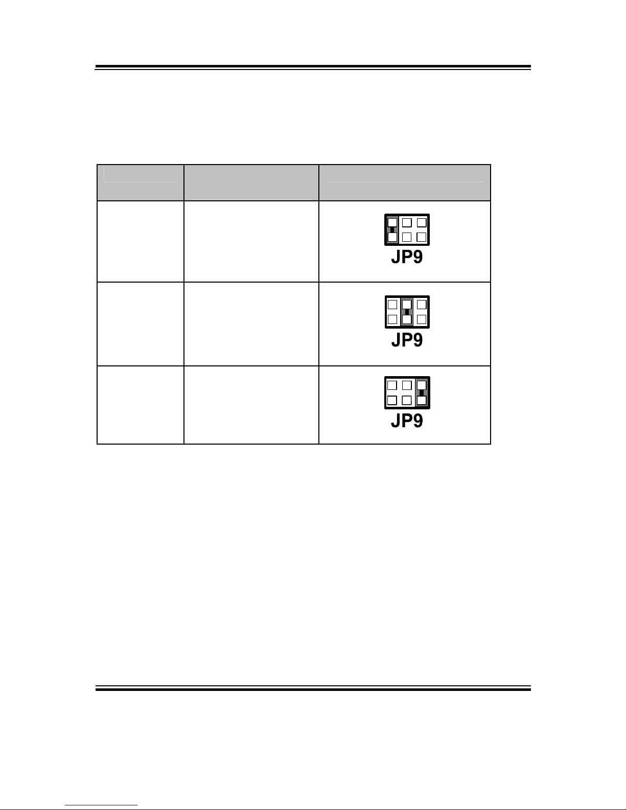
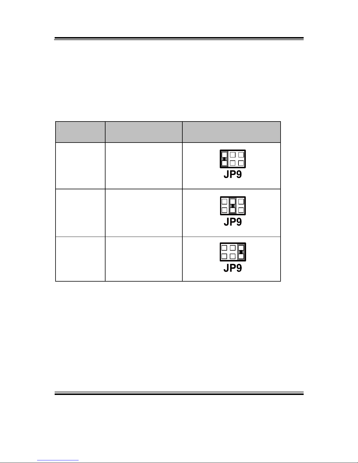
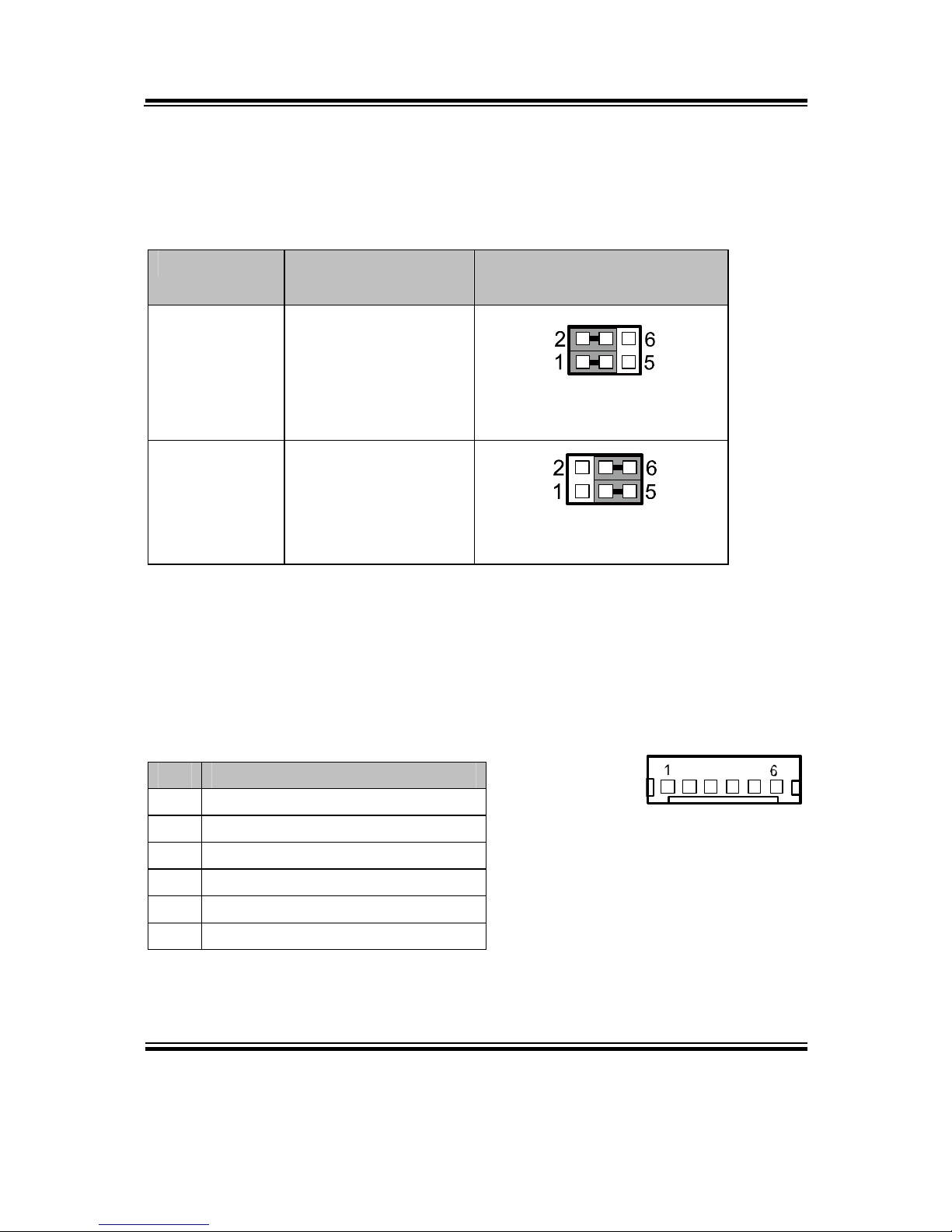
2-6. COM PORT RI & VOLTAGE SELECTION (WIN XP & 7)
JP9: COM3 Port RI & Voltage Selection
The pin assignments are as follows:
SELECTION JUMPTER SETTING
(pin closed)
JUMPER ILLUSTRATION
RI 1-2
1
2
5
6
12V 3-4
1
2
5
6
5V 5-6
1
2
5
6
Note: Manufacturing default – RI
Chapter 2 Hardware Configuration
Page: 2-12
EB-591LF USER′S MANUAL
2-7. COM PORT RI & VOLTAGE SELECTION (WIN CE 6.0:
OPTIONAL)
Caution: COM3 will be assigned as COM4 in Win CE 6.0.
JP9: COM4 Port RI & Voltage Selection
The pin assignments are as follows:
SELECTION JUMPTER SETTING
(pin closed)
JUMPER ILLUSTRATION
RI 1-2
1
2
5
6
12V 3-4
1
2
5
6
5V 5-6
1
2
5
6
Note: Manufacturing default – RI
Chapter 2 Hardware Configuration
EB-591LF USER′S MANUAL
Page: 2-13
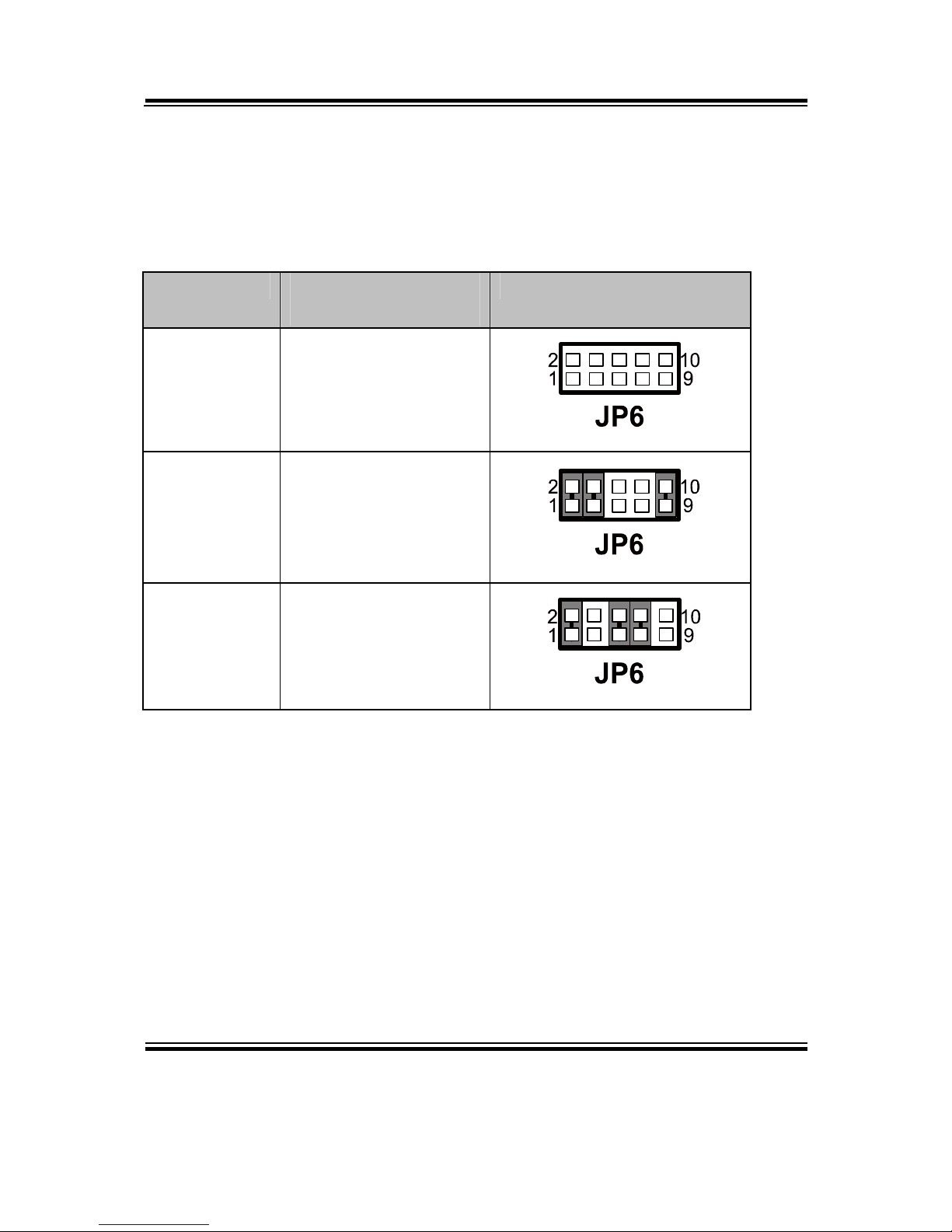
2-8. RS232/422/485 SELECTION (WIN XP & 7)
JP6: RS232/422/485 (COM3) Selection
This connector is used to set the COM3 function.
The jumper settings are as follows:
SELECTION JUMPER SETTINGS
(pin closed)
JUMPER ILLUSTRATION
RS232 All Open
RS422
1-2
3-4
9-10
RS485
1-2
5-6
7-8
Note: Manufacturing default – RS232
Chapter 2 Hardware Configuration
Page: 2-14
EB-591LF USER′S MANUAL
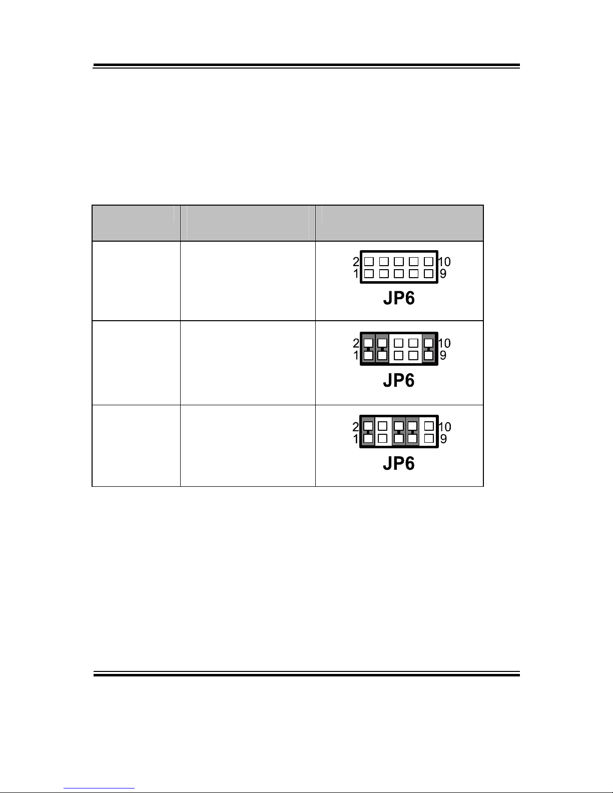
2-9. RS232/422/485 SELECTION (WIN CE 6.0: OPTIONAL)
Caution: COM3 will be assigned as COM4 in Win CE 6.0.
JP6: RS232/422/485 (COM4) Selection
This connector is used to set the COM4 function.
The jumper settings are as follows:
SELECTION JUMPER SETTINGS
(pin closed)
JUMPER ILLUSTRATION
RS232 All Open
RS422
1-2
3-4
9-10
RS485
1-2
5-6
7-8
Note: Manufacturing default – RS232

Chapter 2 Hardware Configuration
EB-591LF USER′S MANUAL
Page: 2-15
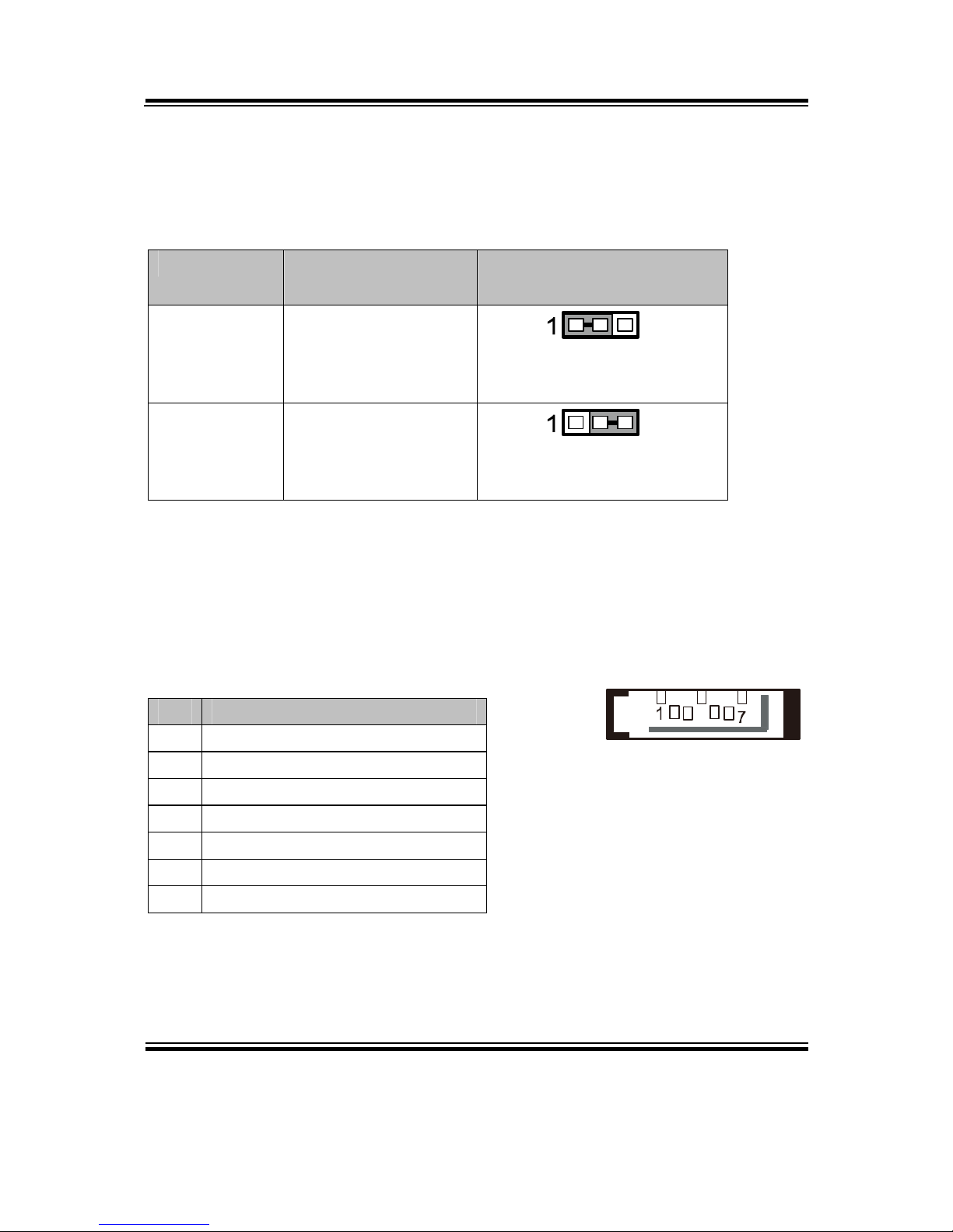
2-10. AUTO RS485 SELECTION (WIN XP & 7)
JP5: Auto RS485 (COM3) Selection
This connector is used to set the COM3 function.
The jumper settings are as follows:
SELECTION JUMPER SETTINGS
(pin closed)
JUMPER ILLUSTRATION
Auto
RS485
1-2
JP5
No Auto
RS485
2-3
JP5
Note: Manufacturing default – Auto RS485

Chapter 2 Hardware Configuration
Page: 2-16
EB-591LF USER′S MANUAL
2-11. AUTO RS485 SELECTION (WIN CE 6.0: OPTIONAL)
Caution: COM3 will be assigned as COM4 in Win CE 6.0.
JP5: Auto RS485 (COM4) Selection
This connector is used to set the COM4 function.
The jumper settings are as follows:
SELECTION JUMPER SETTINGS
(pin closed)
JUMPER ILLUSTRATION
Auto
RS485
1-2
JP5
No Auto
RS485
2-3
JP5
Note: Manufacturing default – Auto RS485

Chapter 2 Hardware Configuration
EB-591LF USER′S MANUAL
Page: 2-17
2-12. UNIVERSAL SERIAL BUS CONNECTOR
USB1: Universal Serial Bus Connector
The pin assignments are as follows:
PIN ASSIGNMENT PIN ASSIGNMENT
1 VCCUSB1 5 VCCUSB1
2 USB0N 6 USB1N
3 USB0P 7 USB1P
4 GND 8 GND
USB2: Internal Universal Serial Bus Connector
The pin assignments are as follows:
PIN ASSIGNMENT PIN ASSIGNMENT
1 VCC5 6 USB3P
2 VCC5 7 GND
3 USB2N 8 GND
4 USB3N 9 GND
5 USB2P 10 GND
USBD1: Client USB Connector
The pin assignments are as follows:
PIN ASSIGNMENT
1 Client USB Detect
2 USB_N
3 USB_P
4 NC
5 GND
USB2
15
USBD1

Chapter 2 Hardware Configuration
Page: 2-18
EB-591LF USER′S MANUAL
2-13. AUDIO CONNECTOR
AUDIO1: AUDIO Port Connector
The pin assignments are as follows:
PIN ASSIGNMENT PIN ASSIGNMENT
1 MIC-L 6 LINE-IN-R
2 MIC-R 7 GND
3 GND 8 GND
4 GND 9 LINE-OUT-L
5 LINE-IN-L 10 LINE-OUT-R
2-14. SYSTEM FAN CONNECTOR
FAN1: System Fan Connector
The pin assignments are as follows:
PIN ASSIGNMENT
1 GND
2 Fan speed control
3 Fan tachometer
AUDIO1
FAN1

Chapter 2 Hardware Configuration
EB-591LF USER′S MANUAL
Page: 2-19
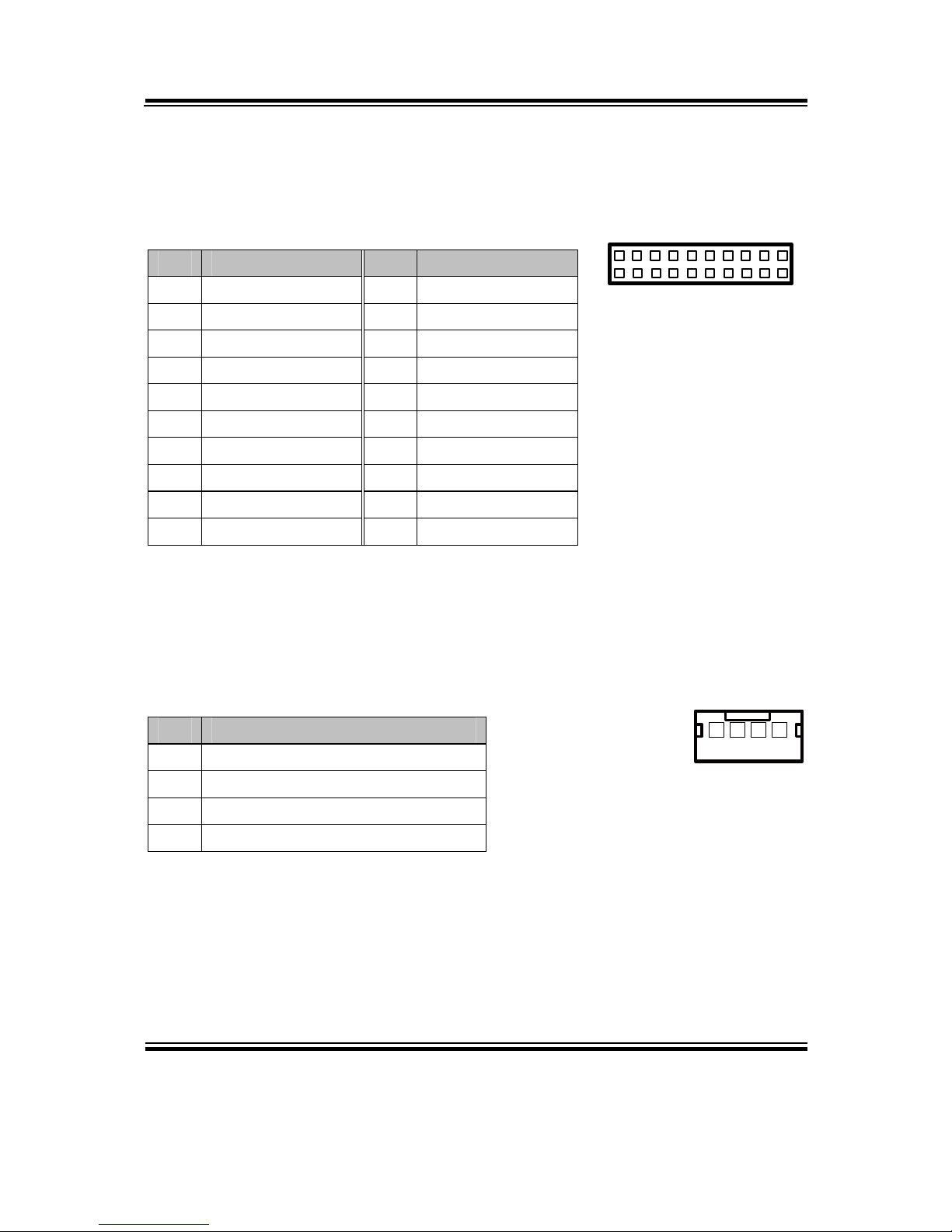
2-15. FRONT PANEL CONNECTOR
FP1: Front Panel Connector
The pin assignments are as follows:
PIN ASSIGNMENT PIN ASSIGNMENT
1 HDDLED+ 7 Reset
2 POWERLED+ 8 EXT_SPK
3 HDDLED- 9 PS_IN
4 POWERLED- 10 EXT_SPK
5 GND 11 GND
6 SPEAKER VCC 12 EXT_SPK
2-16. POWER CONNECTOR
POWER_IN1: Power in 12V Connector
The pin assignments are as follows:
2-17. HDD POWER CONNECTOR
HDD_POWER1: HDD Power Connector
The pin assignments are as follows:
PIN ASSIGNMENT
1 VCC12
2 VCC12
3 GND
4 GND
PIN ASSIGNMENT
1 VCC5
2 GND
Note: 5V/2A storage devices are not supported.
1
11
2
12
FP1
POWER_IN1
1
HDD_POWER1

Chapter 2 Hardware Configuration
Page: 2-20
EB-591LF USER′S MANUAL
2-18. DIGITAL INPUT/OUTPUT CONNECTOR
J5: Digital I/O Connector
The pin assignments are as follows:
PIN ASSIGNMENT PIN ASSIGNMENT
1 VCC5 6 DOUT1
2 GND 7 DIN2
3 DIN0 8 DOUT2
4 DOUT0 9 DIN3
5 DIN1 10 DOUT3
2-19. SDIO CONNECTOR
SDIO1: SDIO Connector
The pin assignments are as follows:
PIN ASSIGNMENT PIN ASSIGNMENT
1 SDIO_DATA2 7 GND
2 SDIO_DATA3 8 SDIO__DATA0
3 SDIO_CMD 9 SDIO__DATA1
4 GND 10 SDIO_CDJ
5 VCC3_3 11 GND
6 SDIO_CLK 12 SDIO_WP
J5
12
1
SDIO1

Chapter 2 Hardware Configuration
EB-591LF USER′S MANUAL
Page: 2-21
2-20. SDVO CONNECTOR
SDVO1: SDVO Connector
The pin assignments are as follows:
SDVO1
PIN ASSIGNMENT PIN ASSIGNMENT
1 VCC5 14 VCC5
2 SDVO_RED_P 15 SDVO_INT_P
3 SDVO_RED_N 16 SDVO_INT_N
4 SDVO_GREEN_P 17 SDVO_STALL_P
5 SDVO_GREEN_N 18 SDVO_STALL_N
6 SDVO_BLUE_P 19 SDVO_TVCLKIN_P
7 SDVO_BLUE_N 20 SDVO_TVCLKIN_N
8 SDVO_CLK_P 21 VCC3_3
9 SDVO_CLK_N 22 VCC3_3
10 SDVO_CTRLDATA 23 VCC12
11 SDVO_CTRLCLK 24 VCC12
12 RESET_J 25 SPEAKER
13 GND 26 GND
Chapter 2 Hardware Configuration
Page: 2-22
EB-591LF USER′S MANUAL
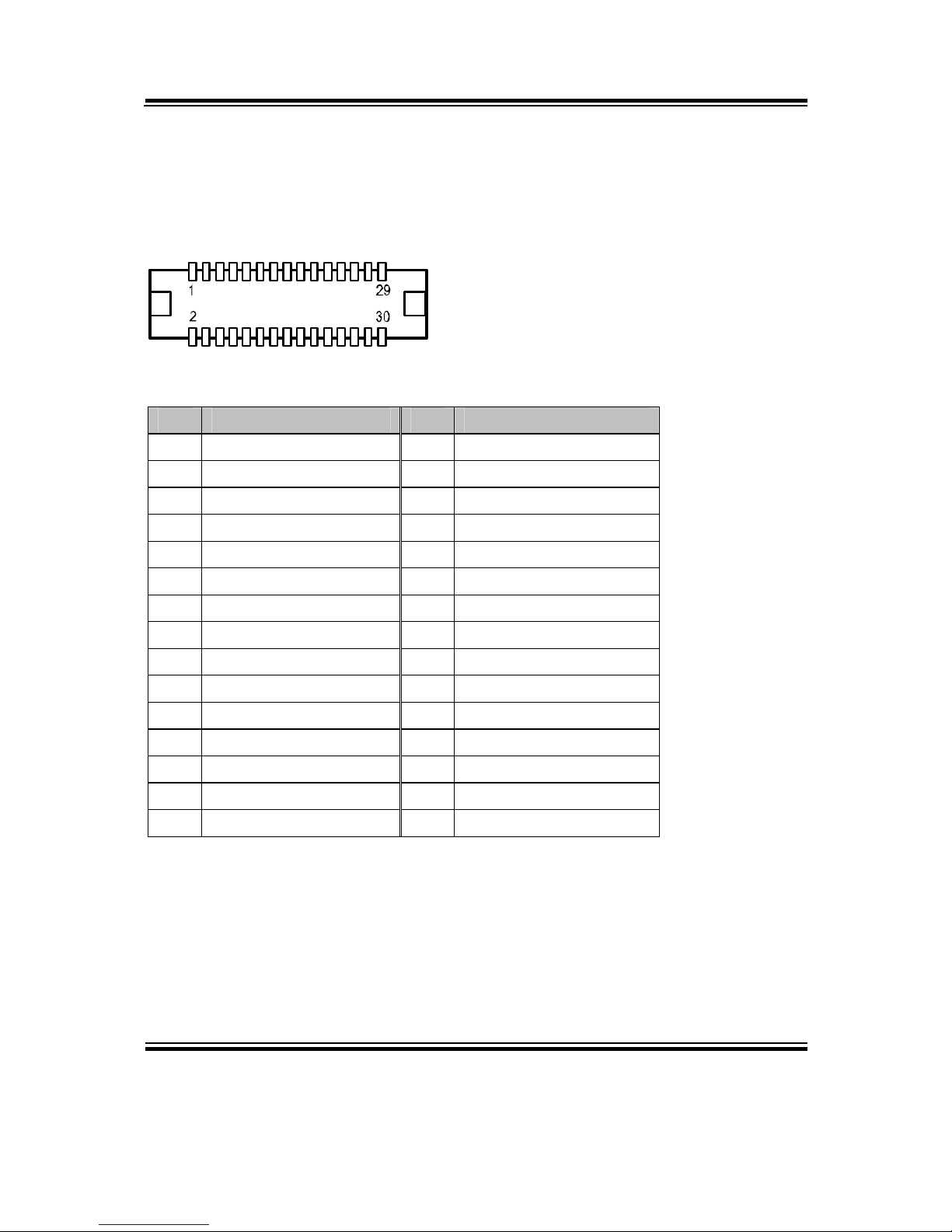
2-21. LVDS CONNECTOR
LVDS1: LVDS Connector
The pin assignments are as follows:
LVDS1
PIN ASSIGNMENT PIN ASSIGNMENT
1 LVDS_VCC 16 LVDS_CLK_P
2 GND 17 LVDS_CLK_N
3 NC 18 GND
4 NC 19 LVDS_DATA2_P
5 GND 20 LVDS_DATA2_N
6 NC 21 GND
7 NC 22 LVDS_DATA1_P
8 GND 23 LVDS_DATA1_N
9 NC 24 GND
10 NC 25 LVDS_DATA0_P
11 NC 26 LVDS_DATA0_N
12 NC 27 LVDS_DATA3_P
13 NC 28 LVDS_DATA3_N
14 NC 29 LVDS_VCC
15 GND 30 LVDS_VCC
Chapter 2 Hardware Configuration
EB-591LF USER′S MANUAL
Page: 2-23
2-22. LVDS VOLTAGE SELECTION
JP2: LVDS Voltage Selection
The jumper settings are as follows:
SELECTION JUMPER SETTING
(pin closed)
JUMPER ILLUSTRATION
VCC3.3
1-3
2-4
JP2
VCC5
3-5
4-6
JP2
Note: Manufacturing default – VCC3.3
2-23. LVDS POWER CONNECTOR
INV1: LVDSBKLT Power Connector
The pin assignments are as follows:
PIN ASSIGNMENT
1 VCC12
2 VCC12
3 GND
4 VCC5
5 GND
6 BKLTEN
INV1
Chapter 2 Hardware Configuration
Page: 2-24
EB-591LF USER′S MANUAL
2-24. AT / ATX POWER SELECTION
JP8: AT/ATX Power Selection
The jumper settings are as follows:
SELECTION JUMPER SETTING
(pin closed)
JUMPER ILLUSTRATION
AT 1-2
JP8
ATX 2-3
JP8
Note: Manufacturing default – AT
2-25. SERIAL ATA CONNECTOR
SATA1: Serial ATA Connector
The pin assignments are as follows:
PIN ASSIGNMENT
1 GND
2 SATA1_TX+
3 SATA1_TX-
4 GND
5 SATA1_RX-
6 SATA1_RX+
7 GND
SATA1
Chapter 2 Hardware Configuration
EB-591LF USER′S MANUAL
Page: 2-25
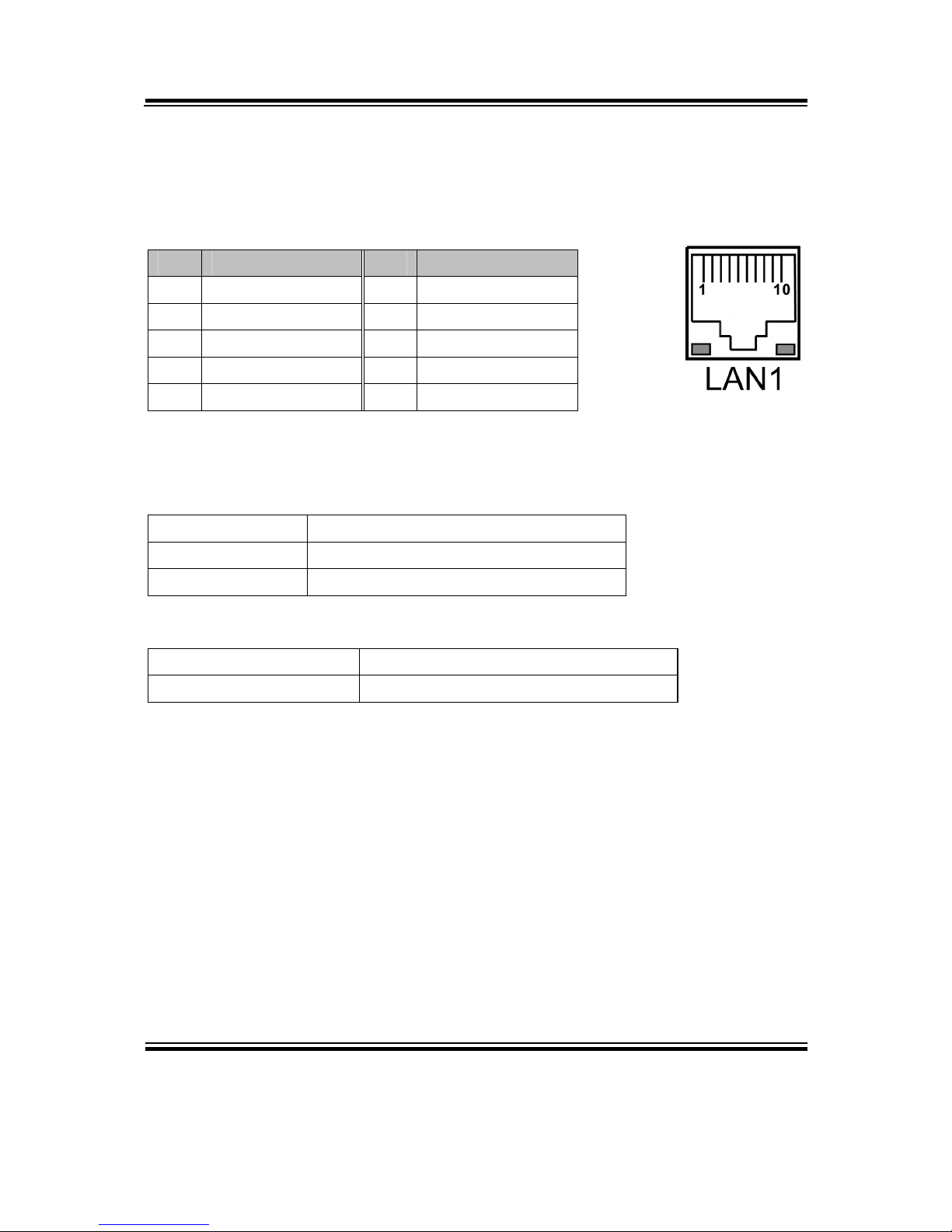
2-26. LAN CONNECTOR
LAN1: LAN Connector
The pin assignments are as follows:
PIN ASSIGNMENT PIN ASSIGNMENT
1 MDI0+ 6 GND
2 MDI0- 7 MDI2+
3 MDI1+ 8 MDI2-
4 MDI1- 9 MDI3+
5 LAN_POWER 10 MDI3-
LAN LED Indicator:
Left Side LED
Green Color On 10/100 LAN Speed Indicator
Orange Color On Giga LAN Speed Indicator
Off No LAN switch/ hub connected.
Right Side LED
Yellow Color Blinking LAN Message Active
Off No LAN Message Active
Chapter 2 Hardware Configuration
Page: 2-26
EB-591LF USER′S MANUAL
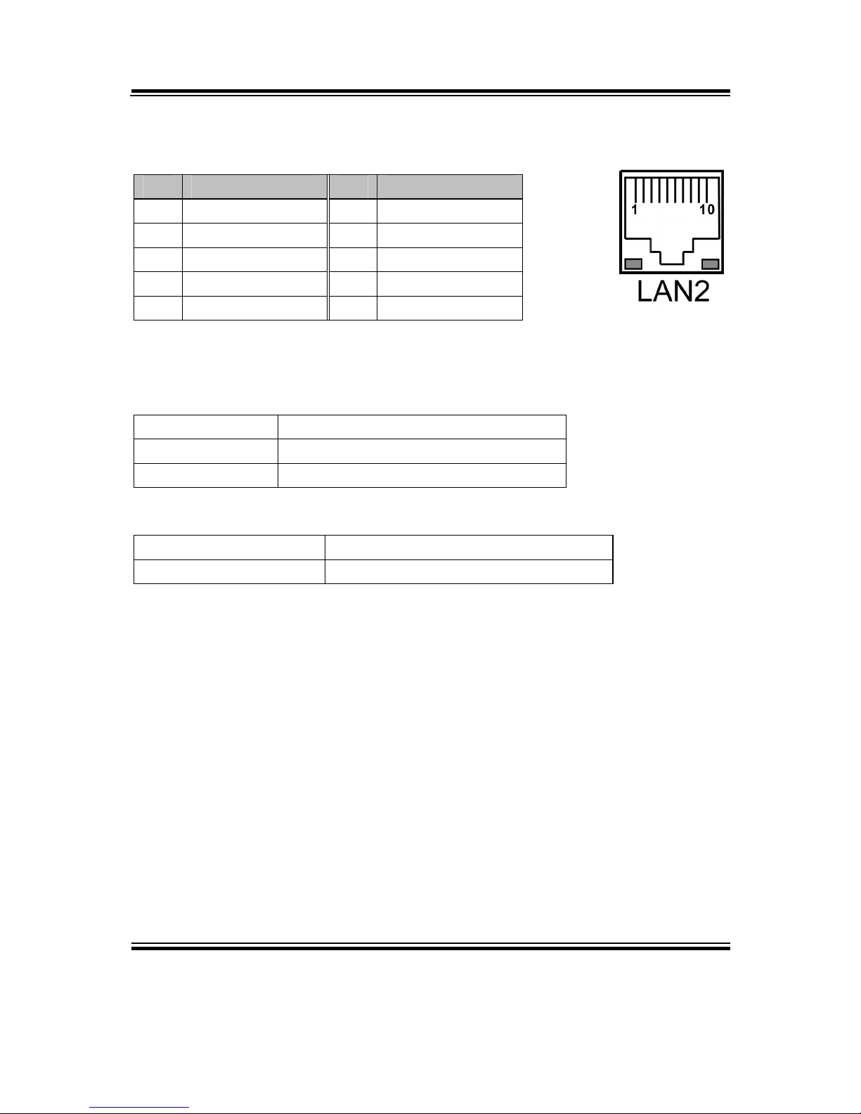
LAN2: LAN Connector
The pin assignments are as follows:
PIN ASSIGNMENT PIN ASSIGNMENT
1 MDI0+ 6 GND
2 MDI0- 7 MDI2+
3 MDI1+ 8 MDI2-
4 MDI1- 9 MDI3+
5 LAN_POWER 10 MDI3-
LAN LED Indicator:
Left Side LED
Green Color On 10/100 LAN Speed Indicator
Orange Color On Giga LAN Speed Indicator
Off No LAN switch/ hub connected.
Right Side LED
Yellow Color Blinking LAN Message Active
Off No LAN Message Active
Chapter 2 Hardware Configuration
EB-591LF USER′S MANUAL
Page: 2-27
2-27. LPC CONNECTOR
LPC1: LPC Connector
The pin assignments are as follows:
PIN ASSIGNMENT PIN ASSIGNMENT
1 CLK 11 LPC_AD0
2 GND 12 GND
3 LPC_LFRAMEJ 13 SMB_CLK
4 NC 14 SMB_DATA
5 Reset 15 VCC3_3_SB
6 VCC5 16 LPC_SERIRQ
7 LPC_AD3 17 GND
8 LPC_AD2 18 LPC_CLKRUNJ
9 VCC3_3 19 S3J
10 LPC_AD1 20 LPC_DREQJ0
2-28. CAN BUS CONNECTOR
CAN1: CAN Bus Connector
The pin assignments are as follows:
PIN ASSIGNMENT
1 VCC5
2 CAN_L
3 CAN_H
4 GND
1
CAN1
LPC1
1
220
19
Chapter 2 Hardware Configuration
Page: 2-28
EB-591LF USER′S MANUAL
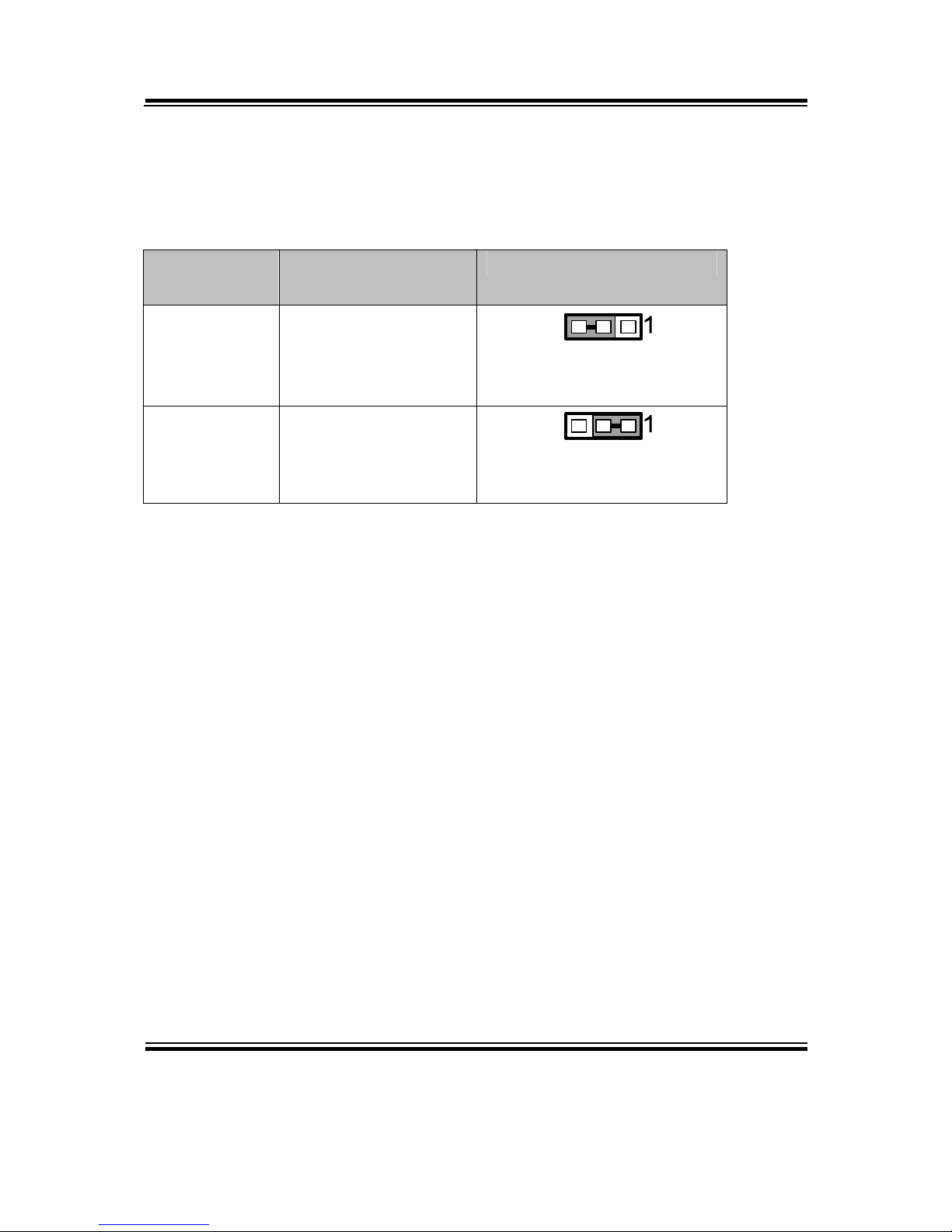
2-29 LOAD DEFAULT SELECTION
JP10: Load Default Selection
The jumper settings are as follows:
SELECTION JUMPER SETTING
(pin closed)
JUMPER ILLUSTRATION
Keep Setting 2-3
JP10
Load Default 1-2
JP10
Note: Manufacturing default – Keep Setting

Page: 3-1
SOFTWARE
UTILITIES
This chapter comprises the detailed information of VGA driver, LAN
driver, and Sound driver.
Sections included:
Introduction.
Intel® Chipset Software Installation Utility
VGA Driver Utility
LAN Driver Utility
Sound Driver Utility
RS232 Driver Utility
CHAPTER
3

Chapter 3 Software Utilities
Page:3-2
EB-591LF USER′S MANUAL
3-1. INTRODUCTION
Enclosed with our EB-591LF package are our driver utilities, which come in a format
of CD ROM or floppy disk. Refer to the following table for driver locations:
FILENAME
(Assume that CD ROM drive is D:)
PURPOSE
D:\Driver\IOH\ Intel® IOH Driver Files for Windows
System installation
D:\Driver\Utility Intel® IOH Chipset Device Software
Installation Utility
D:\Driver\VGA Intel® Corporation Atom E6xx Embedded
Media and Graphics Driver installation
D:\Driver\LAN Intel® 82574(L) for LAN Driver installation
D:\Driver\Sound Realtek ALC888 for Sound driver
installation
D:\Driver\RS232 RS232 Modify Parameters Utility for
Windows installation
D:\Driver\BIOS AMI BIOS Update Utility
Note: Be sure to install the Utility right after the OS fully installed.

Chapter 3 Software Utilities
EB-591LF USER′S MANUAL
Page:3-3
3-2. INTEL® C HIPSET SOFTWARE INSTALLATION UTILITY
3-2-1. Introduction
The Intel® Chipset Device Software installs Windows *.INF files to the target system,
and this package contains the drivers for all the interfaces such as USB, SATA, I2C,
SPI of the Intel® Platform Controller Hub EG20T with information about a piece of
hardware on the system. These files outline to the operating system how to configure
the Intel® chipset components in order to ensure that the following features function
properly:
- DMA Support
- GPIO Support
- I2C Support
- Packet HUB Support
- Serial Peripheral Interface (SPI) Support
- PCIe Support
- IDE/ATA33/ATA66/ATA100 Storage Support
- SATA Storage Support
- USB Support
3-2-2. Installation of Utility for Windows XP/7
The Utility Pack is to be installed only for Windows XP/7 series, and it should be
installed right after the OS installation. Please follow the steps below:
1. Insert the driver disk into a CD ROM device.
2. Under Windows system, go to the directory where the Utility driver is located.
3. Run the application with administrative privileges.

Chapter 3 Software Utilities
Page:3-4
EB-591LF USER′S MANUAL
3-3. VGA DRIVER UTILITY
3-3-1. Introduction
The VGA interface embedded with our EB-591LF can support a wide range of display.
You can display CRT, LVDS simultaneously with the same mode.
1. Win XP Series
2. Win 7 Series
3-3-2. Installation of VGA Driver
To install the VGA Driver, simply follow the following steps:
1. Insert the driver disk into a CD ROM device.
2. Under Windows system, go to the directory where the VGA driver is located.
3. Run the application with administrative privileges..

Chapter 3 Software Utilities
EB-591LF USER′S MANUAL
Page:3-5
3-4. LAN DRIVER UTILITY
3-4-1. Introduction
EB-591LF is enhanced with LAN function that can support various network adapters.
Installation programs for LAN drivers are listed as follows:
1. Win XP Series
2. Win 7 Series
For more details on Installation procedure, please refer to Readme.txt file found
on LAN Driver Utility.

Chapter 3 Software Utilities
Page:3-6
EB-591LF USER′S MANUAL
3-5. SOUND DRIVER UTILITY
3-5-1. Introduction
The Realtek sound function enhanced in this system is fully compatible with Windows
XP and Windows 7. Below, you will find the content of the Sound driver:
1. Win XP Series
2. Win 7 Series
3-5-2. Installation of Sound Driver
1. Insert the driver disk into a CD ROM device.
2. Under Windows system, go to the directory where the Sound driver is located.
3. Run the application with administrative privileges..
4. Follow the instructions on the screen to complete the installation.
5. Once the installation is completed, shut down the system and restart in order for
the changes to take effect.

Chapter 3 Software Utilities
EB-591LF USER′S MANUAL
Page:3-7
3-6. RS232 DRIVER UTILITY
3-6-1. Introduction
The RS232 driver utility, which is needed for adjusting the serial port frequency, is
fully compatible with Windows XP and Windows 7.
1. Win XP Series
2. Win 7 Series
3-6-2. Installation of RS232 Driver
1. Insert the driver disk into a CD ROM device.
2. Under Windows system, go to the directory where the RS232 driver is located.
3. Run the application with administrative privileges.

Page: 4-1
AMI
BIOS SETUP
This chapter shows how to set up the AMI BIOS.
Sections included:
Introduction
Entering Setup
Main
Advanced
Chipset
Boot
Security
Save & Exit
CHAPTER
4

Chapter 4 AMI BIOS Setup
Page: 4-2
EB-591LF USER′S MANUAL
4-1. INTRODUCTION
The board Prox-E591LF uses an AMI Aptio BIOS that is stored in the Serial
Peripheral Interface Flash Memory (SPI Flash) and can be updated. The SPI Flash
contains the BIOS setup menu, Power-on Self-test (POST), the PCI auto-configuration
utility, LAN EEPROM information, and Plug and Play support.
Aptio is AMI’s BIOS firmware based on the UEFI (Unified Extensible Firmware
Interface) specifications and the Intel Platform Innovation Framework for EFI. The
UEFI specification defines an interface between an operating system and platform
firmware. The interface consists of data tables that contain platform-related
information, boot service calls, and runtime service calls that are available to the
operating system and its loader. These provide standard environment for booting an
operating system and running pre-boot applications.
Following illustration shows Extensible Firmware Interface’s position in the software
stack.

Chapter 4 AMI BIOS Setup
EB-591LF USER′S MANUAL
Page: 4-3
EFI BIOS provides an user interface allow users the ability to modify hardware
configuration, e.g. change system date and time, enable or disable a system component,
decide bootable device priorities, setup personal password, etc., which is convenient
for modifications and customization of the computer system and allows technicians
another method for finding solutions if hardware has any problems.
The BIOS setup menu can be used to view and change the BIOS settings for the
computer. The BIOS setup menu is accessible by pressing the <Del> or <F2> key on
keyboard during the POST stage, right before the operating system is loading. All the
settings are described in chapter to be followed.

Chapter 4 AMI BIOS Setup
Page: 4-4
EB-591LF USER′S MANUAL
4-2. ENTERING SETUP
When the system is powered on, the BIOS will enter the Power-On Self Test (POST)
routines and the following message will appear on the lower screen:
First POST screen with AMI logo
As long as this message is present on the screen you may press the <F2> or <Del>
key (the one that shares the decimal point at the bottom of the number keypad) to
access the setup menu.
Chapter 4 AMI BIOS Setup
EB-591LF USER′S MANUAL
Page: 4-5
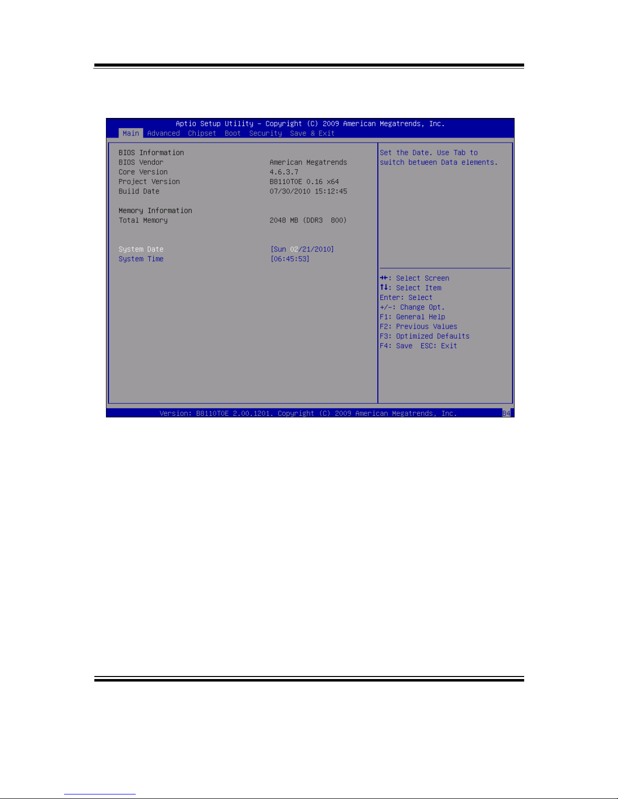
In a moment, the main menu of the Aptio Setup Utility will appear on the screen:
BIOS setup menu initial screen
You may move the cursor by up/down keys to highlight the individual menu items. As
you highlight each item, a brief description of the highlighted selection will appear at
the bottom of the screen.
Chapter 4 AMI BIOS Setup
Page: 4-6
EB-591LF USER′S MANUAL
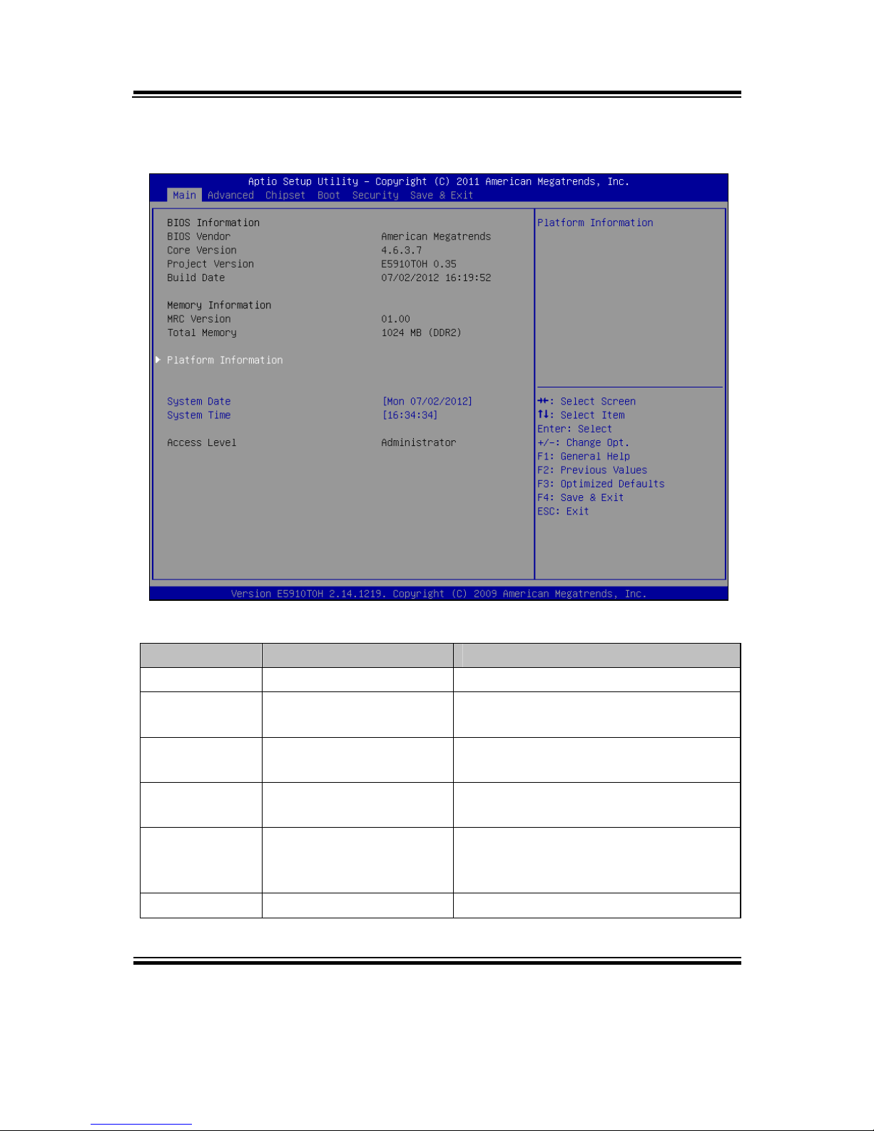
4-3. MAIN
Main screen
BIOS Setting Options Description/Purpose
BIOS Vendor No changeable options Displays the BIOS vendor.
Core Version No changeable options Displays the current BIOS core
version.
Project
Version
No changeable options Displays the version of the BIOS
currently installed on the platform.
Build Date No changeable options Displays the date of current BIOS
version.
MRC Version No changeable options Displays current version of MRC
(Memory Reference Code), e.g.
“1.00”.
Total Memory No changeable options Displays amount of installed memory.

Chapter 4 AMI BIOS Setup
EB-591LF USER′S MANUAL
Page: 4-7
BIOS Setting Options Description/Purpose
System Date Month, day, year Specifies the current date.
System Time Hour, minute, second Specifies the current time.
Access Level No changeable options Displays security level currently in
use.

Chapter 4 AMI BIOS Setup
Page: 4-8
EB-591LF USER′S MANUAL
4-3-1. PLATFORM INFORMATION
Platform information screen
BIOS Setting Options Description/Purpose
Tunnel Creek
Version
No changeable options Displays the E6xx processor
stepping.
PUNIT Build
Date
No changeable options Displays PMIC (Power Management
IC) date of build.
PUNIT Build
Time
No changeable options Displays PMIC (Power Management
IC) time of build.
Chapter 4 AMI BIOS Setup
EB-591LF USER′S MANUAL
Page: 4-9
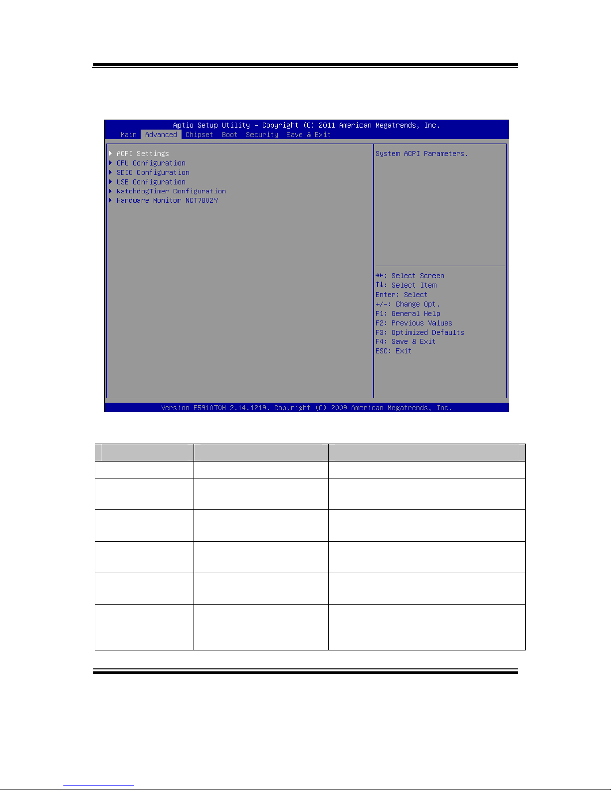
4-4. ADVANCED
Advanced screen
BIOS Setting Options Description/Purpose
ACPI Settings No changeable options Enters menu to set ACPI option.
CPU
Configuration
No changeable options All processor related options menu.
SDIO
Configuration
No changeable options SDIO device configuration section.
USB
Configuration
No changeable options Enters menu to configure USB
options.
WatchdogTimer
Configuration
No changeable options Section to configure Watchdog
Timer.
Hardware
Monitor
NCT7802Y
No changeable options Options for NCT7802Y HW monitor
chip.

Chapter 4 AMI BIOS Setup
Page: 4-10
EB-591LF USER′S MANUAL
4-4-1. ACPI SETTINGS
ACPI settings screen
BIOS Setting Options Description/Purpose
ACPI Sleep
State
-Suspend Disabled
-S3 (Suspend to RAM)
Specifies the ACPI sleep state.
Disabled disables ACPI sleep feature.
S3 allows the platform to enter Sleep
mode (also known as Standby or
Suspend to RAM).
Note: It is necessary to modify system registry in order to enable wake up from S3 system
power state via USB devices in Windows XP. Simply add DWORD entry named
"USBBIOSx" with value 0 to location:
HKEY_LOCAL_MACHINE\SYSTEM\CurrentControlSet\Services\usb\
Fore more details, refer to Microsoft Support article KB 841858 at
http://support.microsoft.com/kb/841858.
Chapter 4 AMI BIOS Setup
EB-591LF USER′S MANUAL
Page: 4-11
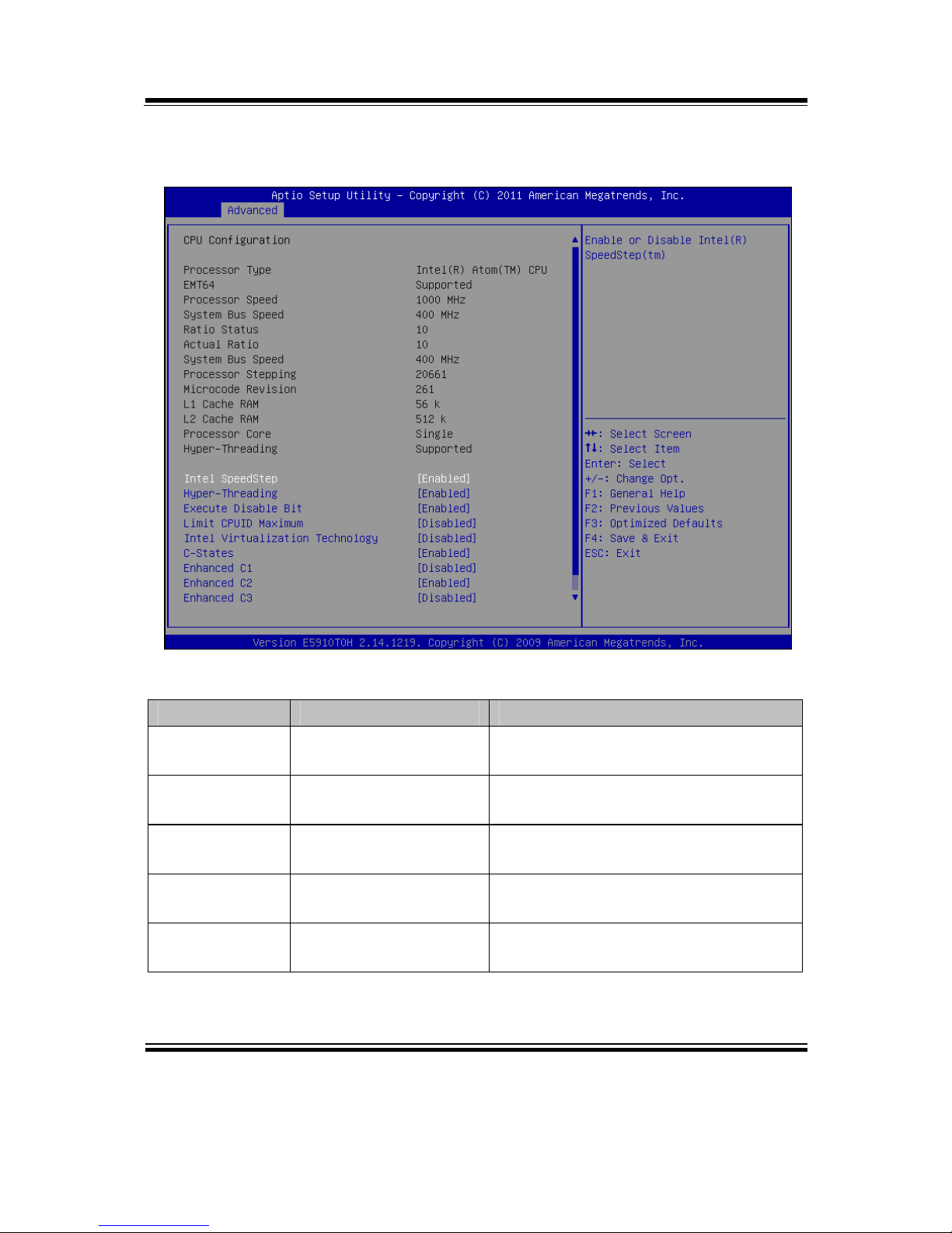
4-4-2. CPU CONFIGURATION
CPU configuration screen
BIOS Setting Options Description/Purpose
Processor Type No changeable options Displays the current processor model
number.
EMT64 No changeable options Reports if processor supports Intel
x86-64 (amd64) implementation.
Processor
Speed
No changeable options Displays the current processor
frequency.
System Bus
Speed
No changeable options Displays the bus frequency.
Processor
Stepping
No changeable options Displays processor’s ID stepping.

Chapter 4 AMI BIOS Setup
Page: 4-12
EB-591LF USER′S MANUAL
BIOS Setting Options Description/Purpose
Microcode
Revision
No changeable options Displays processor's microcode
update revision.
L1 Cache RAM No changeable options Displays amount of Level 1 cache.
L2 Cache RAM No changeable options Displays amount of Level 2 cache.
Processor
Cores
No changeable options Displays information about number of
physical cores in processor.
HyperThreading
No changeable options Reports if Intel Hyper-Threading
Technology is supported by
processor.
Intel SpeedStep -Disabled
-Enabled
Enables Intel SpeedStep feature for
dynamic scaling processor frequency.
Hyperthreading
-Disabled
-Enabled
When disabled, only one thread per
active core will operate.
Execute
Disable Bit
-Disabled
-Enabled
Enables the NX bit (No eXecute)
security feature.
Limit CPUID
Maximum
-Disabled
-Enabled
Enables for legacy operating systems
to boot processors with extended
CPUID functions.
Intel
Virtualization
Technology
-Disabled
-Enabled
Enables or disables Intel
Virtualization Technology (VT-x).
Takes affect only after power cycling.
C-States -Disabled
-Enabled
Enables or disables C states (C2 and
above) in processor.
Enhanced C1 -Disabled
-Enabled
Allows processor to enter its C1 idle
state.
Enhanced C2 -Disabled
-Enabled
Allows processor to enter its C2 idle
state.
Enhanced C3 -Disabled
-Enabled
Allows processor to enter its C3 idle
state.
Enhanced C4 -Disabled
-Enabled
Allows processor to enter its C4 idle
state.

Chapter 4 AMI BIOS Setup
EB-591LF USER′S MANUAL
Page: 4-13
4-4-5. SDIO CONFIGURATION
SDIO configuration screen
BIOS Setting Options Description/Purpose
SDIO Access
Mode
-auto
-DMA
-PIO
Configures SDIO (Secure Digital
Input Output) interface as following:
Auto Mode selects mode in
automatic fashion.
DMA Mode allows use Direct
Memory Access method.
PIO Mode enables Programmed
input/output method.

Chapter 4 AMI BIOS Setup
Page: 4-14
EB-591LF USER′S MANUAL
4-4-6. USB CONFIGURATION
USB configuration screen
BIOS Setting Options Description/Purpose
USB Devices No changeable options Reports number and type of connected
USB devices if any.
Legacy USB
Support
-Enabled
-Disabled
-Auto
Enables support for USB in legacy
operating systems (e.g. MS-DOS,
Windows NT).
EHCI Handoff
-Disabled
-Enabled
When enabled it allows BIOS support
control of the EHCI controller and the
OS hand-off synchronization
capability.

Chapter 4 AMI BIOS Setup
EB-591LF USER′S MANUAL
Page: 4-15
BIOS Setting Options Description/Purpose
USB transfer
time-out
-1 sec
-5 sec
-10 sec
-20 sec
Specifies time-out value for Control,
Bulk and Interrupt transfers.
Device reset
time-out
-10 sec
-20 sec
-30 sec
-40 sec
Specifies the value for device reset
timeout.
Device powerup delay
-Auto
-Manual
Specifies maximum time it would take
for USB device to report itself to the
controller. If set to auto, it would use
default values (100 ms for root port)
and value read from hub descriptor in
case of hub port.

Chapter 4 AMI BIOS Setup
Page: 4-16
EB-591LF USER′S MANUAL
4-4-7. WATCHDOG TIMER CONFIGURATION
Watchdog Timer configuration screen
BIOS Setting Options Description/Purpose
Watchdog
Timer
-Disabled
-Enabled
Enables watchdog timer feature.
Timeout Value
for Watchdog
Timer
Multiple options ranging
from 1 to 256
Sets the desired value (in seconds) for
watchdog timer countdown.

Chapter 4 AMI BIOS Setup
EB-591LF USER′S MANUAL
Page: 4-17
4-4-8. HARDWARE MONITOR NCT7802Y
Hardware monitor screen
BIOS Setting Options Description/Purpose
CPU
Temperature
No changeable options Shows processor temperature in
degree Celsius.
Fan Speed No changeable options Displays current speed of fan in
r/min if connected.
Vcore No changeable options Shows actual voltage of processor
core in volt.
VCC 5V No changeable options Monitors 5V section (in volt).
VCC 3.3V No changeable options Monitors 3.3 V section (in volt).

Chapter 4 AMI BIOS Setup
Page: 4-18
EB-591LF USER′S MANUAL
4-5. CHIPSET
Chipset screen
BIOS Setting Options Description/Purpose
North Bridge
Chipset
Configuration
No changeable options All graphics options related menu.
South Bridge
Chipset
Configuration
No changeable options Enters menu to configure south bridge
chipset options.
IOH
Configuration
No changeable options Section to configure platform IO Hub.
Chapter 4 AMI BIOS Setup
EB-591LF USER′S MANUAL
Page: 4-19
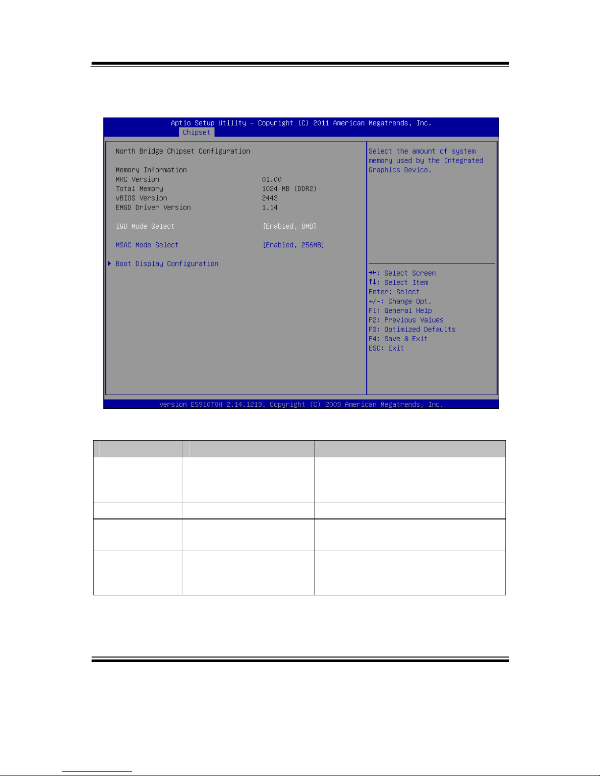
4-5-1. NORTH BRIDGE CHIPSET CONFIGURATION
North bridge chipset configuration screen
BIOS Setting Options Description/Purpose
MRC Version No changeable options Displays current version of MRC
(Memory Reference Code), e.g.
“1.00”.
Total Memory No changeable options Displays the total amount of RAM.
vBIOS Version No changeable options Displays current version of video
BIOS, e.g. “1922”.
IEGD Driver
Version
No changeable options Displays current version of Intel
EMGD (Embedded Media and
Graphics Driver).

Chapter 4 AMI BIOS Setup
Page: 4-20
EB-591LF USER′S MANUAL
BIOS Setting Options Description/Purpose
IGD Mode
Select
-Enabled, 8MB
-Enabled, 16MB
-Enabled, 32MB
-Enabled, 64MB
Specifies the amount of main
memory assigned to Integrated
Graphics Device.
MSAC Mode
Select
-Enabled, 512MB
-Enabled, 256MB
-Enabled, 128MB
Specifies the size of the graphics
memory aperture in function.
Chapter 4 AMI BIOS Setup
EB-591LF USER′S MANUAL
Page: 4-21
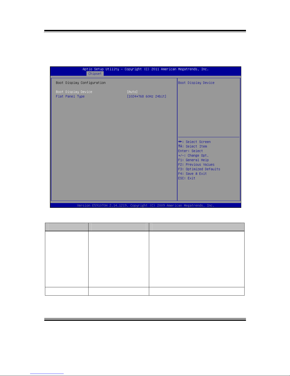
4-5-1-1. NORTH BRIDGE CHIPSET CONFIGURATION - Boot
Display
Boot display configuration screen
BIOS Setting Options Description/Purpose
Boot Display
Device
-Auto
-LVDS
-SDVO
Allows changing boot up screen,
SDVO option is for VGA output, for
panel use LVDS option and Auto
detects available devices and places
picture(s) appropriately. Beware, do
not select option LVDS unless there
is a LVDS panel connected to the
board.
Flat Panel Type -1024*768 60 Hz 24bit Currently limited to one option only.
Chapter 4 AMI BIOS Setup
Page: 4-22
EB-591LF USER′S MANUAL
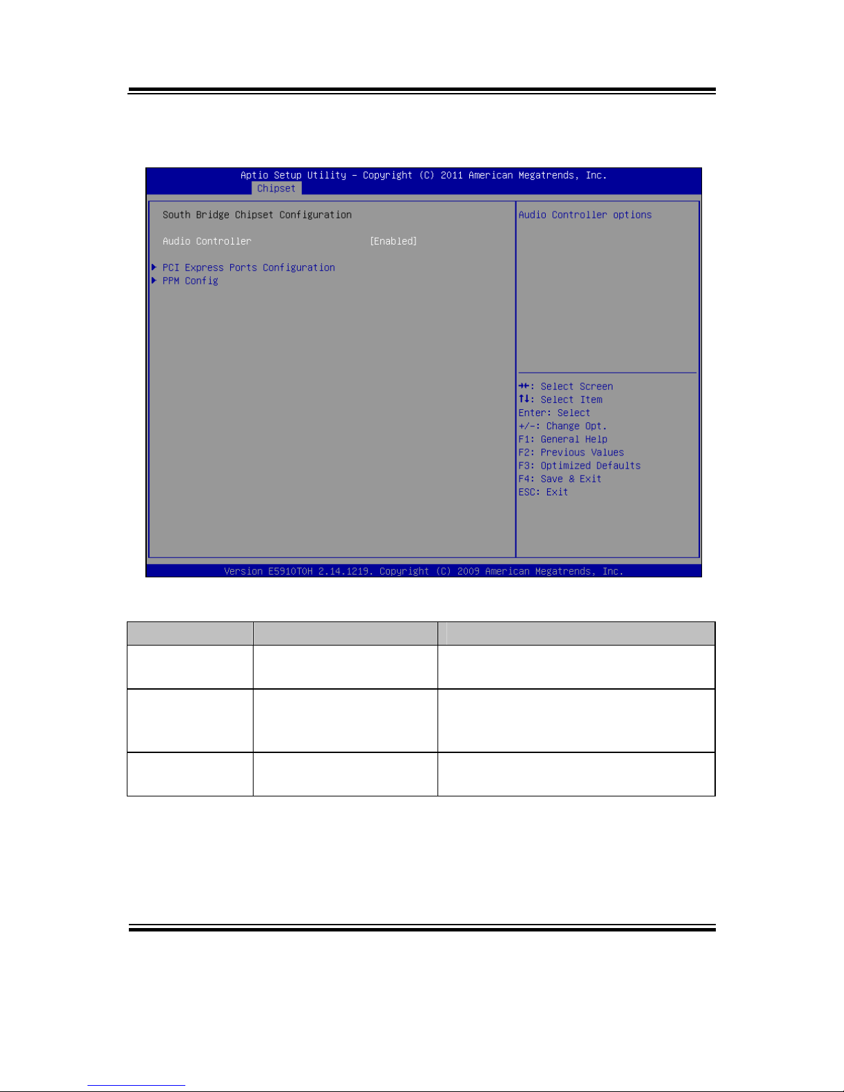
4-5-2. SOUTH BRIDGE CHIPSET CONFIGURATION
South bridge chipset configuration screen
BIOS Setting Options Description/Purpose
Audio
Controller
-Disabled
-Enabled
Enables Intel HD audio controller.
PCI Express
Ports
Configuration
No changeable options Enters menu to configure devices on
PCI Express interface.
PPM Config No changeable options Section to configure additional option
for C-state feature.
Chapter 4 AMI BIOS Setup
EB-591LF USER′S MANUAL
Page: 4-23
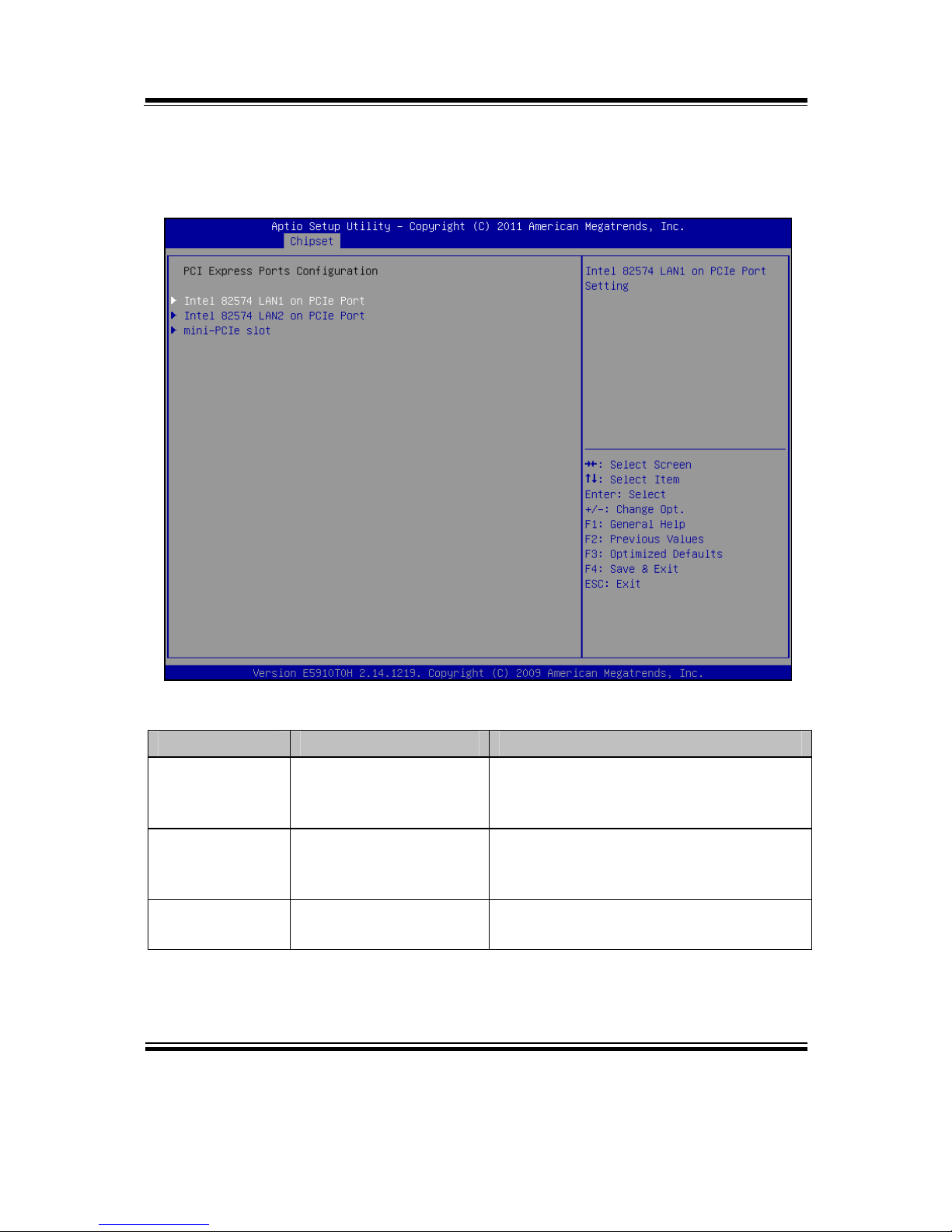
4-5-2-1. SOUTH BRIDGE CHIPSET CONFIGURATION - PCI
EXPRESS PORTS CONFIGURATION
PCI express ports configuration screen
BIOS Setting Options Description/Purpose
Intel 82574
LAN1 on PCIe
Port 1
-Disabled
-Enabled
Controls PCIe root port 1 (LAN1
device).
Intel 82574
LAN1 on PCIe
Port 2
-Disabled
-Enabled
Controls PCIe root port 2 (LAN2
device).
Mini-PCIe slot -Disabled
-Enabled
Controls device on mini-PCIe (on PCIe
root port 3), if inserted.
Chapter 4 AMI BIOS Setup
Page: 4-24
EB-591LF USER′S MANUAL
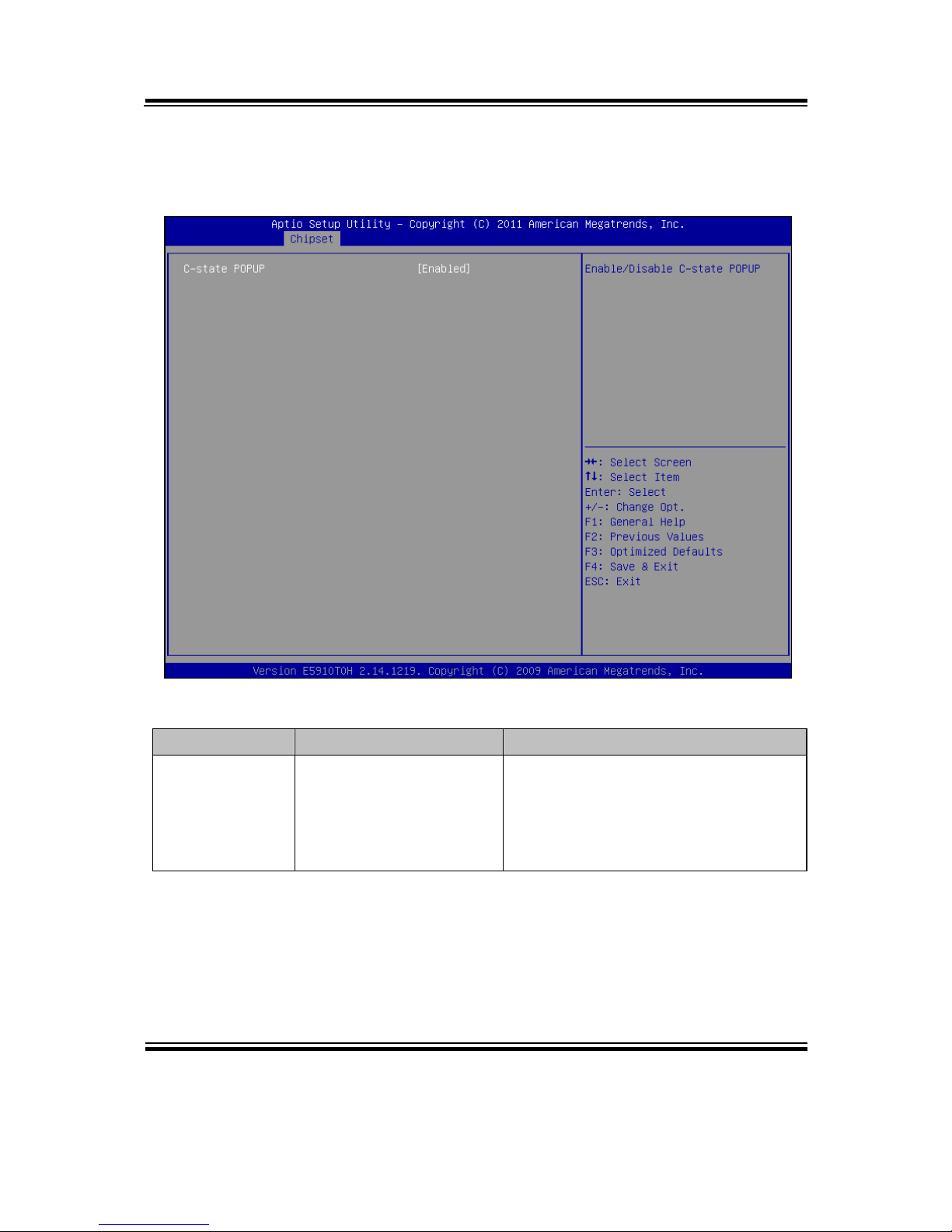
4-5-2-2. SOUTH BRIDGE CHIPSET CONFIGURATION -PPM
CONFIG
PPM config screen
BIOS Setting Options Description/Purpose
C-state POPUP -Disabled
-Enabled
Enables popup mode in which CPU
goes from C3 or C4 state into C2
(when disabled it changes straight to
C0); this is part of PPM (Processor
Power Management).
Chapter 4 AMI BIOS Setup
EB-591LF USER′S MANUAL
Page: 4-25
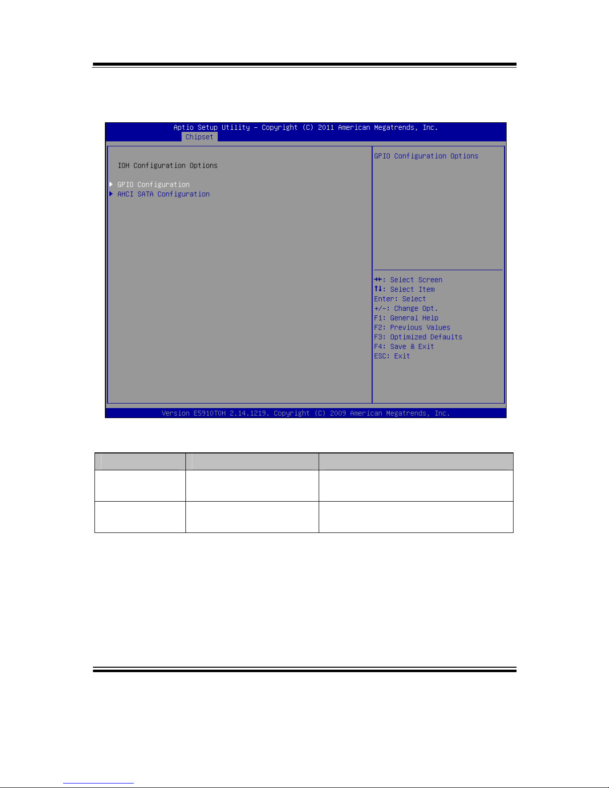
4-5-3. IOH CONFIGURATION
IOH configuration screen
BIOS Setting Options Description/Purpose
GPIO
Configuration
No changeable options Enters menu to configure General
Purpose Input/Output.
AHCI SATA
Configuration
No changeable options Section to configure SATA
controller mode.
Chapter 4 AMI BIOS Setup
Page: 4-26
EB-591LF USER′S MANUAL
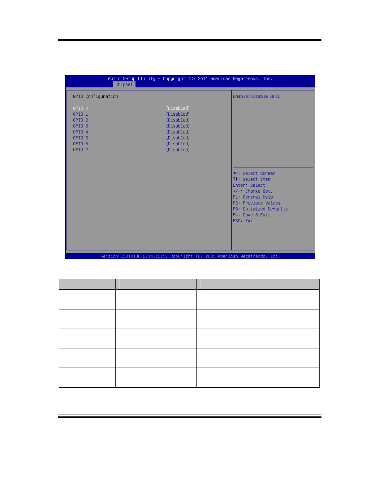
4-5-3-1. IOH CONFIGURATION – GPIO CONFIGURATION
GPIO configuration screen
BIOS Setting Options Description/Purpose
GPIO 0 -Disabled
-Enabled
Enables or disables GPIO 0.
GPIO 1 -Disabled
-Enabled
Enables or disables GPIO 1.
GPIO 2 -Disabled
-Enabled
Enables or disables GPIO 2.
GPIO 3 -Disabled
-Enabled
Enables or disables GPIO 3.
GPIO 4 -Disabled
-Enabled
Enables or disables GPIO 4.

Chapter 4 AMI BIOS Setup
EB-591LF USER′S MANUAL
Page: 4-27
BIOS Setting Options Description/Purpose
GPIO 5 -Disabled
-Enabled
Enables or disables GPIO 5.
GPIO 6 -Disabled
-Enabled
Enables or disables GPIO 6.
GPIO 7 -Disabled
-Enabled
Enables or disables GPIO 7.
Chapter 4 AMI BIOS Setup
Page: 4-28
EB-591LF USER′S MANUAL
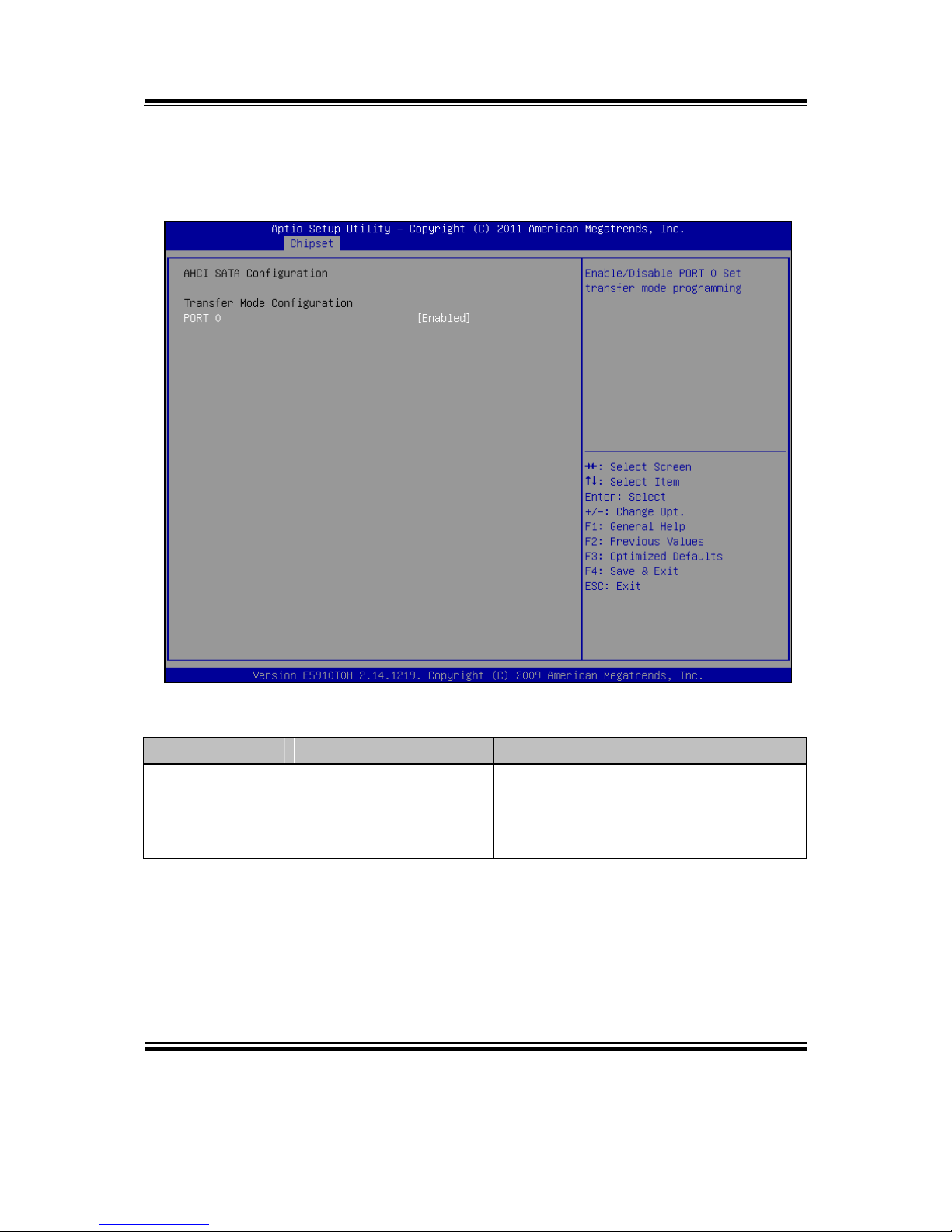
4-5-3-2. IOH CONFIGURATION – AHCI SATA
CONFIGURATION
ACHI SATA Configuration screen
BIOS Setting Options Description/Purpose
Port 0 -Disabled
-Enabled
Configures SATA interface controller,
when disabled it selects PIO mode.
Enabled chooses DMA transfer
mode.

Chapter 4 AMI BIOS Setup
EB-591LF USER′S MANUAL
Page: 4-29
4-6. BOOT
Boot screen
BIOS Setting Options Description/Purpose
Quiet Boot -Disabled
-Dnabled
When quiet boot is enabled, it
displays AMI or OEM logo instead
of POST messages during boot.
Setup Prompt
Timeout
Multiple options ranging
from 1 to 65535
Specifies number of seconds to wait
for setup activation key (value 65535
results in indefinite waiting).
Bootup
NumLock
Status
-On
-Off
Specifies the power-on state of the
numlock feature on the numeric
keypad of keyboard.
CSM16
Module
Version
No changeable options Displays the current Compatibility
Support Module version.

Chapter 4 AMI BIOS Setup
Page: 4-30
EB-591LF USER′S MANUAL
BIOS Setting Options Description/Purpose
Option ROM
Messages
-Force BIOS
-Keep Current
When set to Force BIOS it allows
the POST screen to display Option
ROM messages.
Boot Option #1 -[USB/DVD/ hard
drive(s)]
-disabled
Allows setting up boot option from
menu listed.

Chapter 4 AMI BIOS Setup
EB-591LF USER′S MANUAL
Page: 4-31
4-6-1. HARD DRIVE BBS PRIORITIES
Hard drive BBS priorities screen
BIOS Setting Options Description/Purpose
Boot Option #1 -[Drive(s)]
-Disabled
Allows setting the boot order of
available drive(s).

Chapter 4 AMI BIOS Setup
Page: 4-32
EB-591LF USER′S MANUAL
4-7. SECURITY
Security screen
BIOS Setting Options Description/Purpose
Administrator
Password
Password can be up to
20 alphanumeric
characters.
Specifies the administrator password.
User Password Password can be up to
20 alphanumeric
characters.
Specifies the user password.

Chapter 4 AMI BIOS Setup
EB-591LF USER′S MANUAL
Page: 4-33
4-8. SAVE & EXIT
Save & Exit screen
BIOS Setting Options Description/Purpose
Save Changes
and Exit
No changeable options Exits and saves the changes in
CMOS SRAM.
Discard
Changes and
Exit
No changeable options Exits without saving any changes
made in BIOS settings.
Save Changes
and Reset
No changeable options Saves the changes in CMOS SRAM
and resets.
Discard
Changes and
Reset
No changeable options Resets without saving any changes
made in BIOS settings.
Save Changes No changeable options Saves the changes done in BIOS
settings so far.

Chapter 4 AMI BIOS Setup
Page: 4-34
EB-591LF USER′S MANUAL
BIOS Setting Options Description/Purpose
Discard
Changes
No changeable options Discards the changes done in BIOS
settings so far.
Restore
Defaults
No changeable options Loads the optimized defaults for
BIOS settings.
Save as User
Defaults
No changeable options Saves the current values as user
defaults.
Restore User
Defaults
No changeable options Loads the user defaults for BIOS
settings.
Boot Override -[drive(s)] Forces to boot from selected
[drive(s)].

Page: A-1
EXPANSION
BUS
This appendix indicates the pin assignments.
Sections included:
Mini PCI-E Bus Connector Pin Assignment
APPENDIX
A

Appendix A Expansion Bus
Page: A-2
EB-591LF USER′S MANUAL
MINI PCI-E BUS CONNECTOR PIN ASSIGNMENT
You will find a Mini PCI-e connector on EB-591LF.
The pin assignments are as follows:
PIN ASSIGNMENT PIN ASSIGNMENT
1 WAKE# 27 GND
2 +3.3V 28 +1.5V
3 Reserved 29 GND
4 GND 30 SMB_CLK
5 Reserved 31 PETn0
6 +1.5V 32 SMB_DATA
7 CLKREQ# 33 PETp0
8 Reserved 34 GND
9 GND 35 GND
10 Reserved 36 USB_D11 REFCLK- 37 GND
12 Reserved 38 USB_D+
13 REFCLK+ 39 +3.3V
14 Reserved 40 GND
15 GND 41 +3.3V
16 Reserved 42 Reserved
17 Reserved 43 GND
18 GND 44 Reserved
19 Reserved 45 Reserved
20 Reserved 46 Reserved
21 GND 47 Reserved
22 PERST# 48 +1.5V
23 PERn0 49 Reserved
24 +3.3Vaux 50 GND
25 PERp0 51 Reserved
26 GND 52 +3.3V

Page: B-1
TECHNICAL
SUMMARY
This section introduce you the maps concisely.
Sections included:
Block Diagram
Interrupt Map
DMA Channel Map
I/O Map
Memory Map
Watchdog Timer Configuration
Flash BIOS Update
APPENDIX
B
Appendix B Technical Summary
Page: B-2
EB-591LF USER′S MANUAL
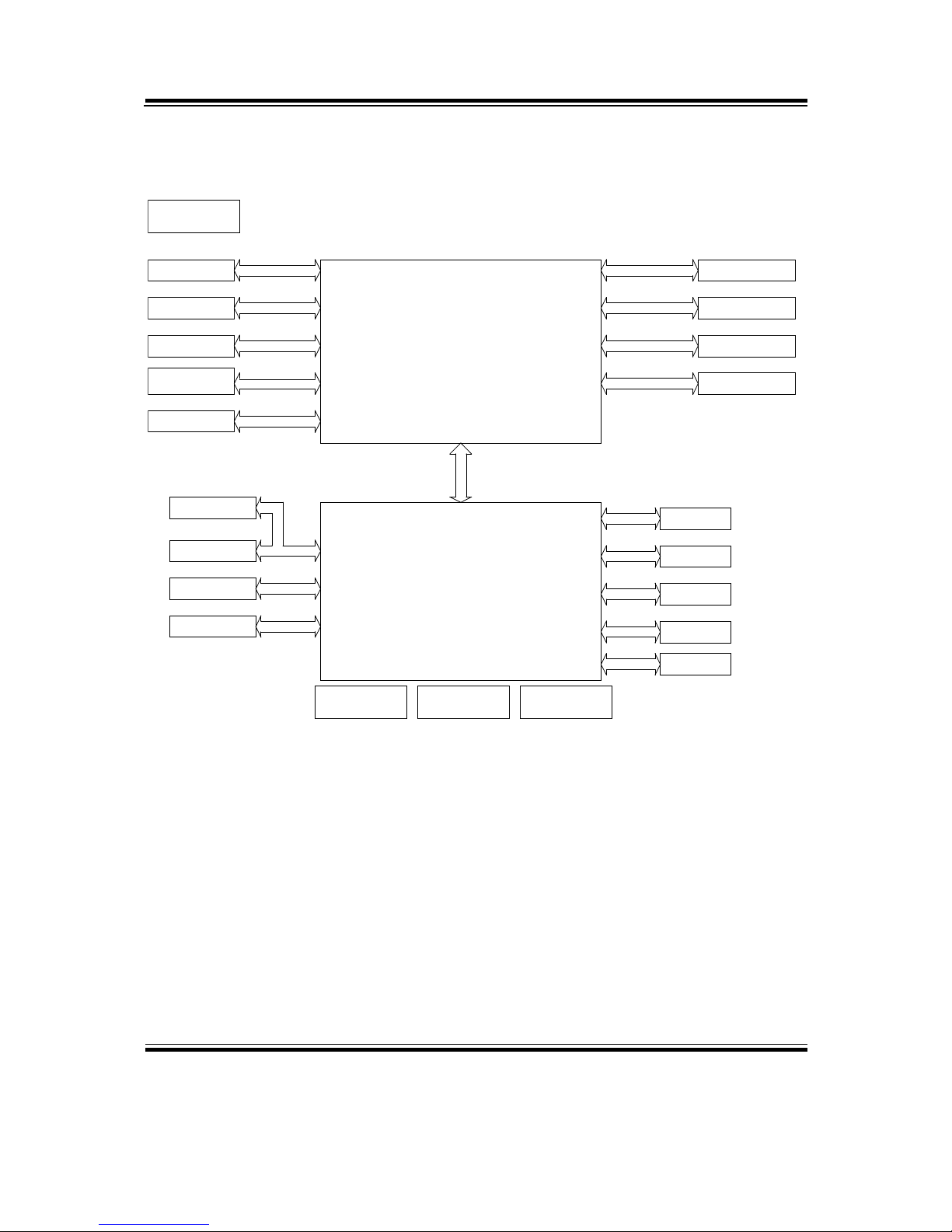
BLOCK DIAGRAM
Intel Tunnel Creek Processor
FCBGA 636
DDR2
Soldered-down DRAM
600 MHz (Ultra Low Power SKU)
1.0 GHz (Entry SKU)
1.3 GHz (Mainstream SKU)
1.6 GHz (Premium SKU)
512K Cache
Giga LAN
DDR2 800 MT/s
PCI-E 1X
w/ inverter connector
LVDS
Single channel 24 bits
Pin Header 2 X 13
SDVO
LOW PIN COUNTER
Pin Header 2 X 10
TPM Connector
Intel Atom processor E6xx series
PCI-E 1X
Giga LAN
NCT7802Y
Hardware Monitor
Intel 82574IT
Intel 82574IT
PCI-E 1X Mini PCI Express Slot
16Mb
HD CODEC
FirmWare Hub
ALC888
HD Codec
SPI
BE9595M WV
Pin Header 1 x 7
Clock Generator
BU7335M WV
PCI-E 1X
Topcliff IOH
PCH EG20T
Micro SD
SATA
BE9591AM WV
SDIO
Controller of PMICPower Management IC
SDI O
SATA (1)
w/422/485
8-wire interface
Pin Header 1 X 4
2-wire interface
COM 3
Digital I/O
CAN bus
CAN bus
COM 4/5/6
Digital I/O
(4/4)
USB 2.0 (4)
USB2 .0
clien t USB2. 0
Mini USB
SDVO

Appendix B Technical Summary
EB-591LF USER′S MANUAL
Page: B-3
INTERRUPT MAP
IRQ ASSIGNMENT
0 System timer
3 Ethernet Controller
5 Intel(R) Platform Controller Hub EG20T DMA Controller #2 - 8815
5 Ethernet Controller
8 System CMOS/real time clock
9 Microsoft ACPI-Compliant System
11 Intel Corporation Atom™ E6xx Intel® EMGD Extension
13 Numeric data processor
16 Intel Corporation Atom™ E6xx Intel® EMGD Function 0
16 PCI standard PCI-to-PCI bridge
16 PCI standard PCI-to-PCI bridge
16 Intel(R) Platform Controller Hub EG20T General Purpose IO Controller -
8803
16 Standard OpenHCD USB Host Controller
16 Standard OpenHCD USB Host Controller
16 Standard OpenHCD USB Host Controller
16 Standard Enhanced PCI to USB Host Controller
16 PCI standard PCI-to-PCI bridge
16 PCI standard PCI-to-PCI bridge
16 PCI standard PCI-to-PCI bridge
16 Microsoft UAA Bus Driver for High Definition Audio
17 Intel(R) Platform Controller Hub EG20T SATA AHCI Controller - 880B
18 SDA Standard Compliant SD Host Controller
18 SDA Standard Compliant SD Host Controller
18 Intel(R) Platform Controller Hub EG20T Serial Peripheral Interface Bus -
8816
18 Intel(R) Platform Controller Hub EG20T I2C Controller - 8817
18 Intel(R) Platform Controller Hub EG20T Controller Area Network (CAN)
Controller - 8818
18 Intel(R) Platform Controller Hub EG20T IEEE 1588 Hardware Assist -
8819

Appendix B Technical Summary
Page: B-4
EB-591LF USER′S MANUAL
IRQ ASSIGNMENT
19 Standard OpenHCD USB Host Controller
19 Standard OpenHCD USB Host Controller
19 Standard OpenHCD USB Host Controller
19 Standard Enhanced PCI to USB Host Controller
19 Intel(R) Platform Controller Hub EG20T USB Client Controller - 8808
19 Intel(R) Platform Controller Hub EG20T DMA Controller #1 - 8810
19 Intel(R) Platform Controller Hub EG20T UART Controller - 8811 (COM8)
19 Intel(R) Platform Controller Hub EG20T UART Controller - 8812 (COM9)
19 Intel(R) Platform Controller Hub EG20T UART Controller - 8813
(COM10)
19 Intel(R) Platform Controller Hub EG20T UART Controller - 8814
(COM13)

Appendix B Technical Summary
EB-591LF USER′S MANUAL
Page: B-5
DMA CHANNELS MAP
TIMER CHANNEL ASSIGNMENT
Channel 4 Direct memory access controller

Appendix B Technical Summary
Page: B-6
EB-591LF USER′S MANUAL
I/O MAP
I/O MAP ASSIGNMENT
0x00000000-0x00000CF7 PCI bus
0x00000000-0x00000CF7 Direct memory access controller
0x00000D00-0x0000FFFF PCI bus
0x0000F010-0x0000F017 Intel Corporation Atom™ E6xx Intel® EMGD
Function 0
0x000003B0-0x000003BB Intel Corporation Atom™ E6xx Intel® EMGD
Function 0
0x000003C0-0x000003DF Intel Corporation Atom™ E6xx Intel® EMGD
Function 0
0x0000F000-0x0000F007 Intel Corporation Atom™ E6xx Intel® EMGD
Extension
0x0000E000-0x0000EFFF PCI standard PCI-to-PCI bridge
0x0000E000-0x0000EFFF PCI standard PCI-to-PCI bridge
0x0000E000-0x0000EFFF Intel(R) Platform Controller Hub EG20T SATA
AHCI Controller - 880B
0x0000E070-0x0000E077 Intel(R) Platform Controller Hub EG20T UART
Controller - 8811 (COM8)
0x0000E060-0x0000E067 Intel(R) Platform Controller Hub EG20T UART
Controller - 8812 (COM9)
0x0000E050-0x0000E057 Intel(R) Platform Controller Hub EG20T UART
Controller - 8813 (COM10)
0x0000E040-0x0000E047 Intel(R) Platform Controller Hub EG20T UART
Controller - 8814 (COM13)
0x0000D000-0x0000DFFF PCI standard PCI-to-PCI bridge
0x0000D000-0x0000DFFF Ethernet Controller
0x0000C000-0x0000CFFF PCI standard PCI-to-PCI bridge
0x0000C000-0x0000CFFF Ethernet Controller
0x00000A79-0x00000A79 ISAPNP Read Data Port

Appendix B Technical Summary
EB-591LF USER′S MANUAL
Page: B-7
I/O MAP ASSIGNMENT
0x00000279-0x00000279 ISAPNP Read Data Port
0x00000274-0x00000277 ISAPNP Read Data Port
0x00000020-0x00000021 Programmable interrupt controller
0x00000024-0x00000025 Programmable interrupt controller
0x00000028-0x00000029 Programmable interrupt controller
0x0000002C-0x0000002D Programmable interrupt controller
0x00000030-0x00000031 Programmable interrupt controller
0x00000034-0x00000035 Programmable interrupt controller
0x00000038-0x00000039 Programmable interrupt controller
0x0000003C-0x0000003D Programmable interrupt controller
0x000000A0-0x000000A1 Programmable interrupt controller
0x000000A4-0x000000A5 Programmable interrupt controller
0x000000A8-0x000000A9 Programmable interrupt controller
0x000000AC-0x000000AD Programmable interrupt controller
0x000000B0-0x000000B1 Programmable interrupt controller
0x000000B4-0x000000B5 Programmable interrupt controller
0x000000B8-0x000000B9 Programmable interrupt controller
0x000000BC-0x000000BD Programmable interrupt controller
0x000004D0-0x000004D1 Programmable interrupt controller
0x000004D0-0x000004D1 Motherboard resources
0x00000081-0x00000083 Direct memory access controller
0x00000087-0x00000087 Direct memory access controller
0x00000089-0x0000008B Direct memory access controller

Appendix B Technical Summary
Page: B-8
EB-591LF USER′S MANUAL
I/O MAP ASSIGNMENT
0x0000008F-0x0000008F Direct memory access controller
0x000000C0-0x000000DF Direct memory access controller
0x00000040-0x00000043 System timer
0x00000050-0x00000053 System timer
0x00000070-0x00000077 System CMOS/real time clock
0x00000061-0x00000061 System speaker
0x00000010-0x0000001F Motherboard resources
0x00000022-0x0000003F Motherboard resources
0x00000044-0x0000005F Motherboard resources
0x00000063-0x00000063 Motherboard resources
0x00000065-0x00000065 Motherboard resources
0x00000067-0x0000006F Motherboard resources
0x00000072-0x0000007F Motherboard resources
0x00000080-0x00000080 Motherboard resources
0x00000084-0x00000086 Motherboard resources
0x00000088-0x00000088 Motherboard resources
0x0000008C-0x0000008E Motherboard resources
0x00000090-0x0000009F Motherboard resources
0x000000A2-0x000000BF Motherboard resources
0x000000E0-0x000000EF Motherboard resources
0x000000F0-0x000000FF Numeric data processor
0x00000900-0x0000097F System board
0x000009C0-0x000009FF System board

Appendix B Technical Summary
EB-591LF USER′S MANUAL
Page: B-9
I/O MAP ASSIGNMENT
0x00000400-0x0000043F System board
0x00000480-0x000004BF System board

Appendix B Technical Summary
Page: B-10
EB-591LF USER′S MANUAL
WATCHDOG TIMER CONFIGURATION
Watchdog timer feature in E6xx processor provides a resolution that ranges from 1 µs
to 10 minutes. The timer uses a 35-bit down-counter.
After the interrupt is generated the WDT loads the value from the Preload register into
the WDT’s 35-bit Down-Counter and starts counting down. If the host fails to reload
the WDT before the timeout, the WDT drives the GPIO[4] pin high and sets the
timeout bit (WDT_TIMEOUT). This bit indicates that the System has become
unstable. The GPIO[4] pin is held high until the system is Reset or the WDT times out
again (depends on TOUT_CNF). The process of reloading the WDT involves the
following sequence of writes:
1. Write “80” to offset Bar1 + 0Ch
2. Write “86” to offset Bar1 + 0Ch
3. Write ‘1’ to WDT_RELOAD in Reload Register
The same process is used for setting the values in the preload registers. The only
difference exists in step 3. Instead of writing a ‘1’ to the WDT_RELOAD, you write
the desired preload value into the corresponding Preload register. This value is not
loaded into the 35-bit down counter until the next time the WDT reenters the stage.
For example, if Preload Value 2 is changed, it is not loaded into the 35-bit down
counter until the next time the WDT enters the second stage. GPIO[4] is used for
WDT output (WDT_TOUT) when it is not enabled for GPIO (CGEN[4] = 0).
Features
Selectable Prescaler – approximately 1 MHz (1 µs to 1 s) and approximately 1 KHz (1
ms to 10 min).
33 MHz Clock (30 ns Clock Ticks)
WDT Mode:
Drives GPIO[4] high or inverts the previous value.
Used only after first timeout occurs.
Status bit preserved in RTC well for possible error detection and correction.
Drives GPIO[4] if OUTPUT is enabled.
Timer can be disabled (default state) or Locked (Hard Reset required to disable
WDT).
WDT Automatic Reload of Preload value when WDT Reload Sequence is performed.
In WDT mode, users need to program the preload value 1 register to all 0’s.

Appendix B Technical Summary
EB-591LF USER′S MANUAL
Page: B-11
Example Steps
Enable and start watchdog timer, where Bar1 equals to 280h:
------ Step 1 ----------------------------------------------------------------------------------------
Set CGEN[4]=0
------ Step 2 PCI enable Watchdog ------------------------------------------------------------
D31:F00
84H~87H set 80020080
------ Step 3 set WDTCR - WDT Configuration Register (offset 10h) ------------------
bit4 WDT Reset Enable set "1"
bit2 WDT Prescaler Select set "1"
------ Step 4 set PV1R0 -Preload Value 1 Register 0&1 ----------------------------------
write "80" to offset Bar1 +0Ch
write "86" to offset Bar1 +0Ch
write "1" to WDT_RELOAD in Reload Register
------ Step 5 start to count -----------------------------------------------------------------------
set WDTLR - WDT Lock Register (offset 18h)
bit 1 to "1"

Appendix B Technical Summary
Page: B-12
EB-591LF USER′S MANUAL
Flash BIOS Update
I. Before System BIOS update
1. Prepare a bootable media (ex. USB storage device) which can boot system to
DOS prompt.
2. Copy AMI flash utility for MS-DOS afudos (latest version 2.36) onto bootable
device.
3. Download and save the BIOS file (e.g. E5910T05.rom) to the same folder as
afudos utility.
4. Make sure the target system can first boot to the bootable device.
a. Connect the bootable USB device.
b. Turn on the computer and press <F2> or <Del> key during boot to enter
BIOS setup menu.
c. System will go into the BIOS setup menu.

Appendix B Technical Summary
EB-591LF USER′S MANUAL
Page: B-13
d. Select [Boot] menu as shown on picture below.
e. Select [Hard Drive BBS Priorities], set the USB bootable device to be the
1st boot device.
f. Press <F4> key to save configuration and exit the BIOS setup menu.

Appendix B Technical Summary
Page: B-14
EB-591LF USER′S MANUAL
II. AFUDOS Command for System BIOS Update
AFUDOS.exe is aforementioned AMI firmware update utility; the command line is
shown as below:
AFUDOS <ROM File Name> [option1] [option2]…
You can type AFUDOS /? to see all the definition of each control options. The
recommended options for BIOS ROM update consist of following parameters:
/P: program main BIOS image
/B: program Boot Block
/N: program NVRAM
/X: don’t check ROM ID
Appendix B Technical Summary
EB-591LF USER′S MANUAL
Page: B-15
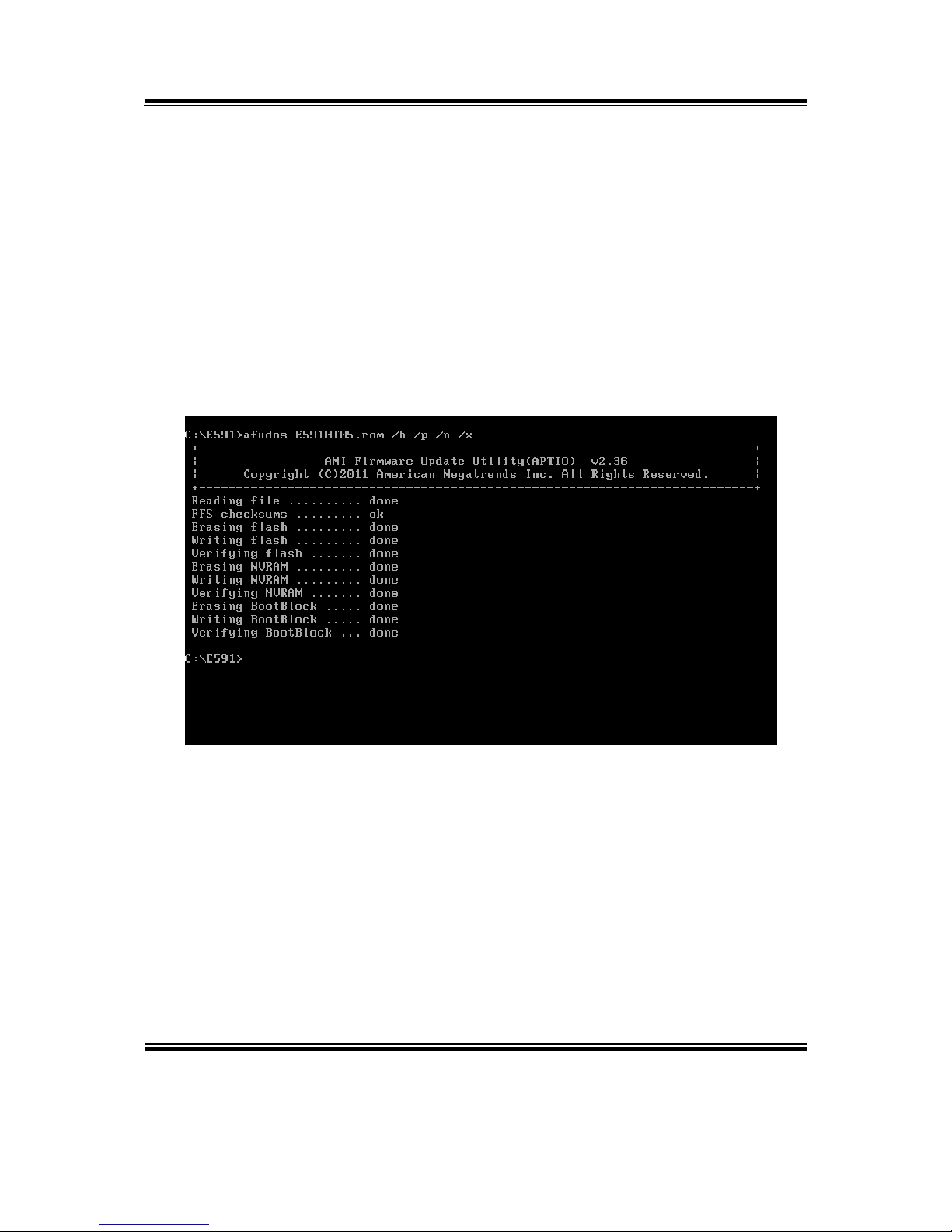
III. BIOS update procedure
1. Use the bootable USB device to boot up system into the MS-DOS command
prompt.
2. Type in
AFUDOS E591xxxx.rom /p /b /n /x and press enter to start the flash
procedure. (Note that xxxx means the BIOS revision part, i.e. 0P01)
3. During the update procedure, you will see the BIOS update process status and its
percentage. Beware! Do not turn off system power or reset your computer if the
whole procedure are not complete yet, or it may crash the BIOS ROM and make
system unable to boot up next time.
4. After BIOS update procedures is complete, the messages from afudos utility
should be like the figure shown right below:
5. Youcan restart the system and boot up with new BIOS now.
6. Update is complete after restart.

Appendix B Technical Summary
Page: B-16
EB-591LF USER′S MANUAL
7. Verify during following boot that the BIOS version -- displayed at first
initialization screen with AMI logo -- has indeed changed:
 Loading...