

Page 1

USER’S
MANUAL
B
M
-0947
Mini-ITX Motherboard
with Intel® 4th Gen. Core i7/i5
features LAN/VGA/8USB/6COM
BM-0947 M1
Page 2

BM-0947
With Intel® 4th Gen. Core
Mini-ITX Motherboard
COPYRIGHT NOTICE & TRADEMARK
All trademarks and registered trademarks mentioned herein are the property of their
respective owners.
This manual is copyrighted in September 2014. You may not reproduce or transmit
in any form or by any means, electronic, or mechanical, including photocopying
and recording.
DISCLAIMER
This operation manual is meant to assist both Embedded Computer manufacturers
and end users in installing and setting up the system. The information contained in
this document is subject to change without any notice.
CE NOTICE
This is a class A product. In a domestic environment this product may cause radio
interference in which case the user may be required to take adequate measures.
Page 3

FCC NOTICE
This equipment has been tested and found to comply with the limits for a Class A
digital device, pursuant to part 15 of the FCC Rules. These limits are designed to
provide reasonable protection against harmful interference when the equipment is
operated in a commercial environment. This equipment generates, uses, and can
radiate radio frequency energy and, if not installed and used in accordance with
the instruction manual, may cause harmful interference to radio communications.
Operation of this equipment in a residential area is likely to cause harmful
interference in which case the user will be required to correct the interference at
his own expense.
You are cautioned that any change or modifications to the equipment not
expressly approve by the party responsible for compliance could void your
authority to operate such equipment.
CAUTION! Danger of explosion if battery is incorrectly replaced. Replace only with the
same or equivalent type recommended by the manufacturer. Dispose of used batteries
according to the manufacturer’s instructions.
Page 4

Contents
TABLE OF CONTENTS
CHAPTER 1 INTRODUCTION
1-1 About This Manual…............................................................ 1-2
1-2 System Specification….......................................................... 1-3
1-3 Safety Precautions…............................................................. 1-5
CHAPTER 2 HARDWARE CONFIGURATION
2-1 Jumper & Connector Quick Reference Table….................... 2-2
2-2 Component Locations….…................................................... 2-3
2-3 How to Set Jumpers…........................................................... 2-5
2-4 COM Port…………………………………………………... 2-7
2-5 COM Connector……………………………………………. 2-8
2-6 VGA Port…………………………………………………... 2-8
2-7 Keyboard & Mouse Port…..……………….......................... 2-9
2-8 LAN & USB3.0 Port...……………………………………... 2-10
2-9 Audio Jack………………………………………………….. 2-11
2-10 USB2.0 Port….…………………………………………….. 2-12
2-11 COM Port RI & Voltage Selection………………………… 2-12
2-12 COM2 RS-232/422/485 Selection…………………………. 2-13
2-13 COM2 Auto-detect Selection………………………………. 2-13
2-14 Front Panel Connector & Selection………………………... 2-14
2-15 Intel® ME Selection………………………………………… 2-15
2-16 Clear CMOS Data Selection……………………………….. 2-16
2-17 BIOS Recovery Mode Selection…………………………… 2-16
2-18 Fan Connector………………………………………............ 2-17
2-19 SATA Connector…………………………………………… 2-17
2-20 USB2.0 Port….…………………………………………….. 2-18
2-21 ATX Power Connector……………………………………... 2-19
2-22 LVDS Connector……………………………………............ 2-20
2-23 LVDS Voltage Selection…….……………………………... 2-21
2-24 LCD Backlight Connector..….……………………………... 2-21
Page 5

Contents
CHAPTER 3 SOFTWARE UTILITIES
3-1 Introduction……………..........................................…......... 3-2
3-2 Intel® Chipset Software Installation Utility……..……..…... 3-4
3-4 Intel® USB3.0 eXtensible Host Controller Utility…………. 3-5
3-5 Intel® Management Engine Components Utillity…………... 3-6
3-6 VGA Driver Utility………………………………….……... 3-7
3-7 LAN Driver Utility……...........................................…......... 3-8
3-8 Sound Driver Utility……………………………………….. 3-9
CHAPTER 4 BIOS SETUP
4-1 Introduction…....................................................................... 4-2
4-2 Entering Setup…................................................................... 4-4
4-3 Main…………...................................................................... 4-6
4-4 Advanced…........................................................................... 4-7
4-5 Chipset…............................................................................... 4-24
4-6 Boot……............................................................................... 4-34
4-7 Security….............................................................................. 4-39
4-8 Save & Exit…....................................................................... 4-42
APPENDIX A EXPANSION BUS
PCIe Bus…………………………………....................................... A-2
APPENDIX B TECHNICAL SUMMARY
Block Diagram….............................................................................. B-2
Interrupt Map…................................................................................ B-3
DMA Channels Map…..................................................................... B-8
I/O Map…........................................................................................ B-9
Memory Map….…………………………………………………… B-12
Watchdog Timer Configuration….………………...……………… B-14
Flash BIOS Update…...............................................….................... B-17
Page 6

Page:1-1
INTRODUCTION
This chapter gives you the information for BM-0947. It also outlines
the system specifications.
Sections included:
About This Manual
System Specifications
Safety Precautions
Experienced users can jump to chapter 2 on page 2-1
for a quick start.
CHAPTER
1
Page 7

Chapter 1 Introduction
BM-0947 USER′S MANUAL
Page: 1-2
1-1. ABOUT THIS MANUAL
Thank you for purchasing our BM-0947 Mini-ITX Motherboard with Intel® 4th
Gen. Core i7/i5 processor, enhanced with LAN, VGA, 8 USB & 6COM, which
is fully PC/AT compatible. The BM-0947 provides faster processing speed,
greater expandability and can handle more tasks than before. This manual is
designed to assist you how to install and set up the system. It contains four
chapters. The user can apply this manual for configuration according to the
following chapters:
Chapter 1 Introduction
This chapter introduces you to the background of this manual, and the
specifications for this system. The final page of this chapter will indicate how to
avoid damaging this board.
Chapter 2 Hardware Configuration
This chapter outlines the component locations and their functions. In the end of
this chapter, you will learn how to set jumper and how to configure this card to
meet your own needs.
Chapter 3 Software Utilities
This chapter contains helpful information for proper installations of the VGA
utility, LAN utility, Sound utility, and Flash BIOS Update. It also describes the
Watchdog-timer configuration.
Chapter 4 BIOS Setup
This chapter indicates you how to set up the BIOS configurations.
Appendix A Expansion Bus
This appendix introduces you the expansion bus for PCIe connectors.
Appendix B Technical Summary
This appendix gives you the information about the Technical maps.
Page 8
Chapter 1 Introduction
BM-0947 USER′S MANUAL
Page: 1-3
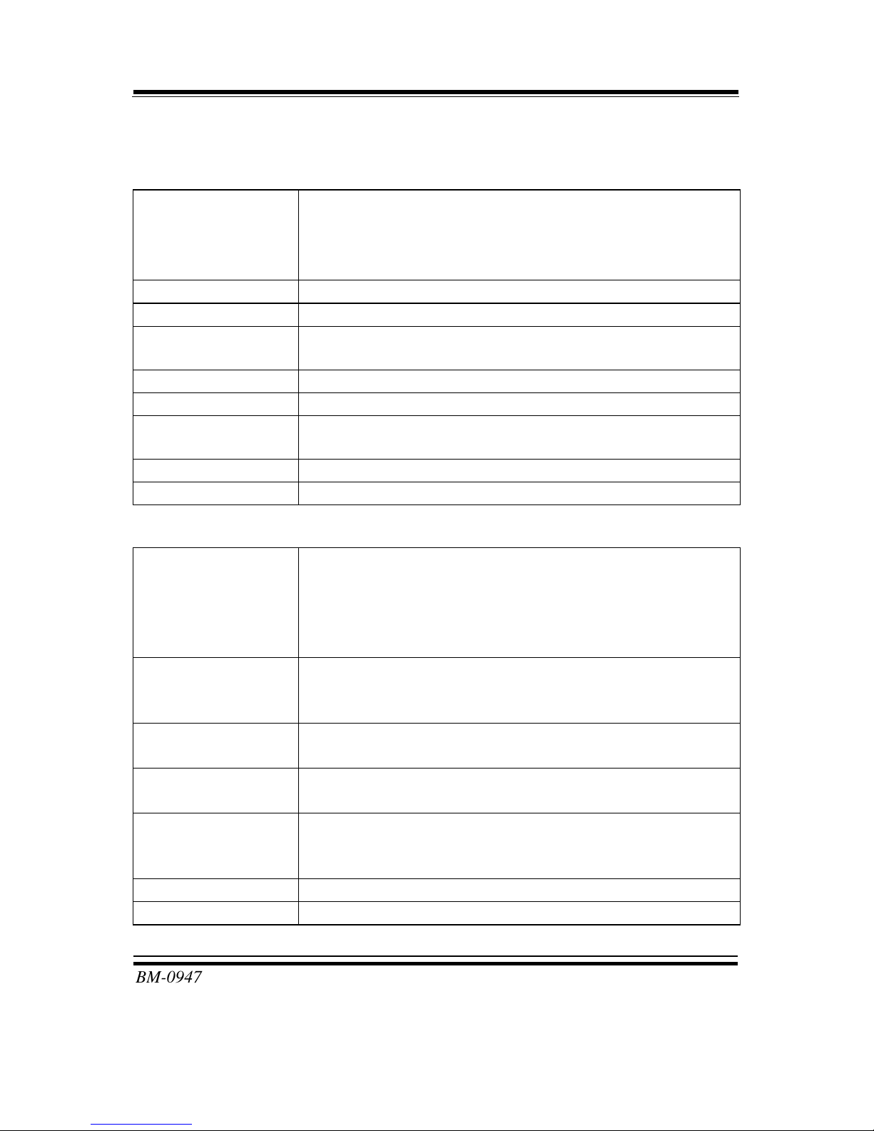
1-2. SYSTEM SPECIFICATIONS
System
CPU
Intel® 4th Gen. Core i5/i7 Processor (LGA1150)
i5-4570S (65W)
i5-4570TE (35W)
i7-4770S (65W)
OS Support Windows 8, 7
Chipset Intel® H81
Memory 2 x SO-DIMM (204 pins), dual channel DDR3-1333/1600
MHz, up to 16GB
BIOS AMI
Watchdog 1~255 seconds
Power Supply ATX 12V & 5VSB (24-pin connector; 4-pin connector for
CPU)
Dimension 170 x 170 mm (6.69” x 6.69”)
Certificate CE/FCC
I/O Ports
Serial Port 6 ports:
COM1/2: COM1 & COM2 D-sub, both COM1 & COM2
are 5V/12V/RI selectable
COM3/4/6: Box headers on board
(COM1/3/4/5/6 for RS-232, COM2 for RS-232/422/485)
USB Port 2 x external USB 3.0, stacked with LAN
6 x USB 2.0 (2 are external ports, 4 are internal pin-
headers.)
SATA Interface Intel® H81: 1 x SATA II, 2 x SATA III
2 x SATA III
LAN 1 port, supports Wake-on-LAN
LAN1: Intel® I217-LM/V
Audio Realtek ALC888S-VD2-GR High Definition audio codec
Line-in/Line-out/MIC
Option: S/PDIF
Keyboard/Mouse 1 x PS/2
Expansion Bus 1 x PCIe (16x) Gen. 2
Page 9
Chapter 1 Introduction
BM-0947 USER′S MANUAL
Page: 1-4
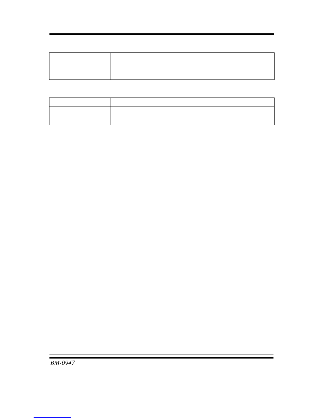
Display
Graphics Built-in processor to share the system memory.
1 x VGA
1 x LVDS (2CH 18/24 bits)
Environment
Operating Temp. 0 ~ 60°C (32 ~ 140°F)
Storage Temp. -40 ~ 80°C (-40 ~ 176°F)
Humidity Operating: 5~90% (non-condensing)
Page 10

Chapter 1 Introduction
BM-0947 USER′S MANUAL
Page: 1-5
1-3. SAFETY PRECAUTIONS
Follow the messages below to avoid your systems from damage:
1. Keep your system away from static electricity on all occasions.
2. Prevent electric shock. Don‘t touch any components of this card when the card is
power-on. Always disconnect power when the system is not in use.
3. Disconnect power when you change any hardware devices.
For instance, when you connect a jumper or install any cards, a surge of power
may damage the electronic components or the whole system.
Page 11

Page 2-1
HARDWARE
CONFIGURATION
** QUICK START **
CHAPTER
2
Helpful information describes the jumper & connector settings, and
component locations.
Sections included:
Jumper & Connector Quick Reference Table
Component Locations
Configuration and Jumper settings
Connector’s Pin Assignments
Page 12

Chapter 2 Hardware Configuration
BM-0947 USER′S MANUAL
Page: 2-2
2-1. JUMPER & CONNECTOR QUICK REFERENCE TABLE
JUMPER/CONNECTOR NAME
COM Port COM1, COM2, COM5
COM Connector COM3, COM4, COM6
VGA Port VGA1
Keyboard & Mouse Port KB_MS1
LAN & USB3.0 Port LAN1_USB1
Audio Jack AUDIO1
COM Port RI & Voltage Selection JPCOM1, JPCOM2
COM2 RS-232/422/485 Selection JP8
COM2 Auto-detect Selection JP7
Front Panel Connector & Selection FP1
Intel® ME Selection JP3
Clear CMOS Data Selection JP4
BIOS Recovery Mode Selection JP1
Fan Connector CPU_FAN1, SYS_FAN1, SYS_FAN2
SATA Connector SATA1, SATA2, SATA3
USB2.0 Port JUSB2, USB3, USB4
ATX Power Connector ATX_PWR1, ATX_PWR2
LVDS Connector LVDS1
LVDS Voltage Selection JP15
LCD Backlight Connector JINV1
Page 13
Chapter 2 Hardware Configuration
BM-0947 USER′S MANUAL
Page: 2-3
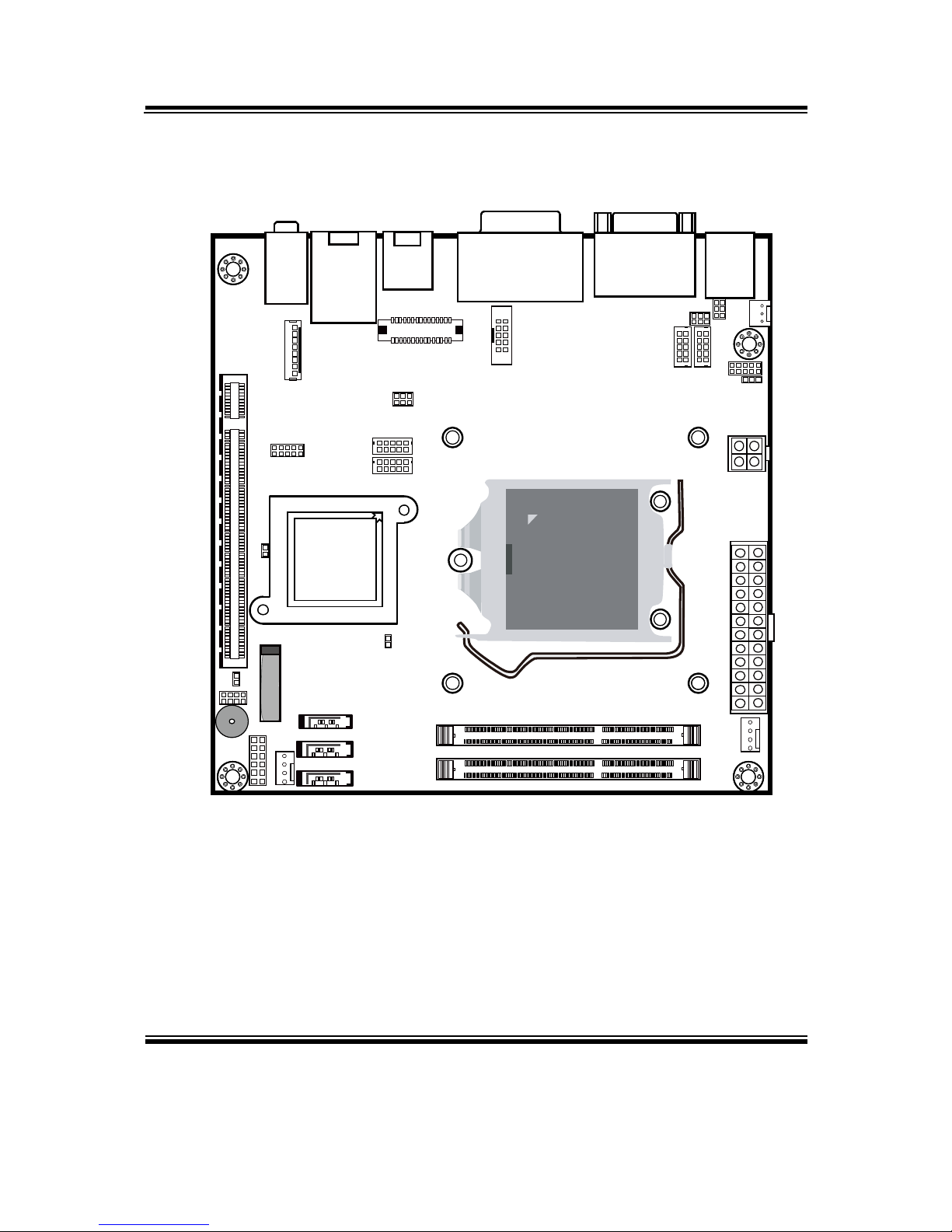
2-2. COMPONENT LOCATIONS
AUDIO1
JP4
JP1
JP3
FP1
SATA3
DIMM2
DIMM1
CPU_ FAN1
SATA2
SATA1
SYS_FAN1
JP6
SP1
USB3
USB4
JP15
JD09M1
JPCOM1
JPCOM2
COM3 COM4
JP7
JP8
ATX_PWR2
ATX_PWR1
SYS_
F
AN2
KB_MS1
LAN1_USB1 JUSB2
LVDS1
COM6
VGA1+COM5
REMOVE
Intel® 4th Gen.
Core™ i5/i7
(LGA1150)
Intel
®
H81/Q87
JLPC1
9
1
0
1
2
1
1
1
Battery
1
2
7
8
125
6
1
4
1
4
17
17
17
12
11
2
1
1
2
717273
74
203
204
1
2
717273
74
203
204
1
2412
341
2
1
3
2
6 5
1
5
2
1
15616
10
1
2
9
10
1
2
9
10
9
102
1
1
30
291
2
5 10
1 6
8
JINV1
1
PCI_E1
BM-0947 Front Connector, Jumper and Component locations
Page 14
Chapter 2 Hardware Configuration
BM-0947 USER′S MANUAL
Page: 2-4
R133
R1094
V6
CM17
CB7
R367
CB77
R378
R380
C241
C64
C55
R708
R750
R728
R735R739
C383
R126
C238
C236
C237
C235
R379
R385
R376
R375
CB6
C246
CM2
U49
R129
R382
R383
C240
R729
U19
V7
R695
C301
C221
C220
C216
C217
R855R854
C410
R845
U41
U43
TP113
R1096
TP125
U45
U46
R1007
R1008
C479
R687R686
Q45
Q48
R697
CE25
C219
C218
C214
C215
R277
R864
R841
R860
R842
Q97
TP152
R863
TP115TP108
TP141
TP140
TP151
R846
TP122TP107
CB74
R1081
R1080
CB75
U42
CB76
TP112
R1087
R1085
C148
D2
TP111
TP123
TP121
C137
R733
C146
R738
R1009
C482
U55
R1001
R1003
C478
C308
R397
R400
L2
R1116
Q146
R1110
Q145
R1113
TP129
TP142
R280
R273
TP143
C154
TP145
TP146
TP147
TP148
C152
R138
CB4
CM13
R105
C114
C147
C164
C141
C142
C150
C139
C153
TP95
R114
R217
R999
R1006
Q118
R995
Q117
U36
Q115
CD13
R398
R402
R405
R406
L4 L3
Q144
R1111
R1105
R852
R849
R1117
C117
C118
FB2
C159
Y2
R283
C110
TP106
TP105
TP138
TP139
R285
R139
C161
R284
R141
R140
C562
C566
C160
C158
C157
C133
TP91
TP90
R100
R227
R91
R233
TP98
TP97
R161
C123
Q119
Q116
Q114
R1019
C225
C493
R1107
CB80
R1115
R1108
R853
Q96
C407
R861
C130
C406
C111
R137
C115
TP86
TP118
R103
R101
R112
R251
R246
TP76
TP75
R121
R204
R208
R202
R102
TP77
TP114
R770R772
C392
R998
R996
C470
R771
C477
R521
R522
C361
C362
C349
C347
FB23
C327
R1017
C488
C354
R1018
Q123
C489
C490
R1112
R1109
C578
R1114
Q95
R848
C405
R271
C151
TP128
TP127
TP87TP124
TP133
C162
C149
TP119
R241R136
R238
R110
R243
C390
R768
R767
R769
C291
C292
R438
R439
C328
C333
U38
R1106
Q94
C492
R302
R272
R859
R856
R851
R288
C116
C163
R230
C126
C140
TP99
R232
R248
R231
R213
R235
R245
R193
R764
R766
C389
Q68
U28
C391
CE5
CB9
FS12
CE28
C496
C491
R866
R867
R865
C408
C612
C611
TP117
TP116
C138
C136
TP110
TP120
TP109
R247
C109
C107
C108
C106
R221
R218
R183
R179
R836
R829
U54
U27
JAPS1
CB8
CB78
R374
R370
C230
C229
C239
C343
C338
R858
R869
R847
R857
U39
R850
R862
CB59
C409
R868
Q100
R705
R703
R700
Q99
R702
R1169
R1168
C380
R1163
R1170
R1162
R760
R1172
TP80
C156
C614
C613
C135
C144
R261
C165
R306
R205
R203
C105
C104
R826
R762
R765
CM46
R513
CB79
R514
R1024
C337
R715
CB56
R757
R1173
R1171
Q66
R758R759
Q8
R267
C143
R832
R216
R226
R225
C393
R833
R827
Q86
R763
R779
R775
C388
R730
R740
R736
C384
R731
U50
R368
R366
U6
CM21
CM20
U9
R1023
R1029
R707
R701
CB54
R710
Q51
R749
R746
R743
Q67
Q43
R683
R682
R680
R156
R90
R278
R116
R279
R113
R185
R184
R99
R780
C394
R774
R778
Q69
R783
R776
R777
C404
C403
R834
D17
CM14
R388
R387
CM47
CM1
R711
R712
R716
R704
R706
R714
R699
CB55
CB53
R713
R709
U23
R744
R747
R752
R751R755
Q65
R754
C386
R753
R672
R674
Q41
R678
R676
Q70
R773
U57
R781
R784
R782
R837
Q90R835
R130
U15
CB84
R597
R592
R600
R601
R593
R596
R599
R598
FS18
R615
R605
R594
R602
C553
R803
C552
R825
R823
R824
U53
V1
CB39
R927
R879
C411
R905
R913
R888
C423
C415
R44
R43
R46
R22
R20
C500
R811
R813
R814
R820
R810
R822
R821
R804
R808
Q79
C397
R816
R812
C399
U16
R873R870
R882
R880
R894
R902
R55
R1090
R56
R1059
R1060
C577CB66
R1061
C549
C550
Q130
U52
R807
R805
C400
R874
R907
R918
R910
R891
R899
R901
R13
R47
R42
R41
R38
R30
R34
R53
CB72
R1062
R815
R802
R806R809
C20
Q80
R73
R74
C398
Q83
R817
R819
R818
R908
R11
R37
R36
R18
R32
R72
R1091
C27
R954
R955
TP15
TP13
TP18
TP74
TP56
TP69
TP45
TP16
TP68
R71
R70
C21
TP11
TP12
TP22
TP49TP48TP46
C44
C40
C41
C2
C45
D11
R956
R1122
R957
C85
C80
R1123
R1124
R949
R948
C42
C32
C49
C83
C54
C6
C22
C8
C9
U31
R545
R548
R547
C53
C43
C51
C30
C29
C79C7C48
C52
C5
C47
TP135
TP150
TP136
R945
R952
R1067
R1068
CB19
CB81
TP27
TP71
C82
C84
C31
C25
C26
C23
C24
C81
C13
C50
TP149
TP137
C439
C443
R1071
R1072
R1070
R1073
TP26
TP72
TP23
R75
R76
R67
C37
R69
C14
R68
TP2
TP31
TP30
TP73
TP24
TP53
C36
R77
R965
R964
R972
R973
TP51TP1
TP52
TP43
TP42
TP41
TP50
TP19
TP40
R1179
C453
C3
TP100
R269
R151
R150
R756
R178
R236
R160
R122
R120
C132
C10
R145
R152
C33
R1189
R1180
R1178
R86
R307
C35
R1182
R83
R144
R460
R840
R838
TP134
C4
R63
R64
R62
C385
R175
R761
R155
R154
C387
R134
R253
R176
U5
R453
R843
R844
Q91
R66
R1083
R1088
R1084
C11
C34
Q7
R308
R1185
R309
R158
R839
Q92
Q98
R65
Q93
R1082
R1097
Q141
R732
R727
R741
R737
R734
R742
R1005
R1002
R1004
R692
R691
Q46
B
E
C
1
2
24
A2
A82
A81
1
2
12
2
1
A1
B1
B2
B81
B82
1
2
6
1
4
3
6
1
4
3
1
7
2
8
4
1
2
22
32
42
36
1
2
1
B
6
C
1
C
E
B
2
E
1
B
E
C
C
C
BEB
6
1
11
6 4
3
1
12
4
3
C
B
E
E
4
3
B
6 4
3
1
E
5
1
48
5
4
E
C
E
B
C
D
BGS
C
1
2
B 1
E
6
11
12
1
1
1
1
8
8
1
C
E
B
C
E
B
E
C
1
3
7
7
7
5
25
35
44
8
1
9
10
A4
B4
C
B
E
B
E
C
B
E
C
3
2
3
4
2
1
1211
2
3
C
B
1
2
C
B
4
1
1
8
8
B
E
C
C
B
E
4
1
C
BEE
5
1
8
B
E
C
8
1
8
E
C
B
E
B
S
G
8
G
S
6
4
3
1
6
4
3
1
C
B
E
B
E
B
E
8 8
1
2
3
1
6
4
1
C
E
B
1
D
C
8
C
G
S
C
D
1 1 1
D
B
E
C
33
32
128
3
1
2
8
1
97
1
96
65
64
E
C
B
E
S
B
C
1
10
24
2 1
9
1
3
4
13
41
3
1
8
1
2
1
8
12
G
1
B
E
C
D
6
1
6
4
3
1
4
3
F
E
A
A
A
ECN:
M/N:
BIOS:
B
B
B
Made in Taiwan
17-143-094202
S/N:
E
C
C
F
SIO
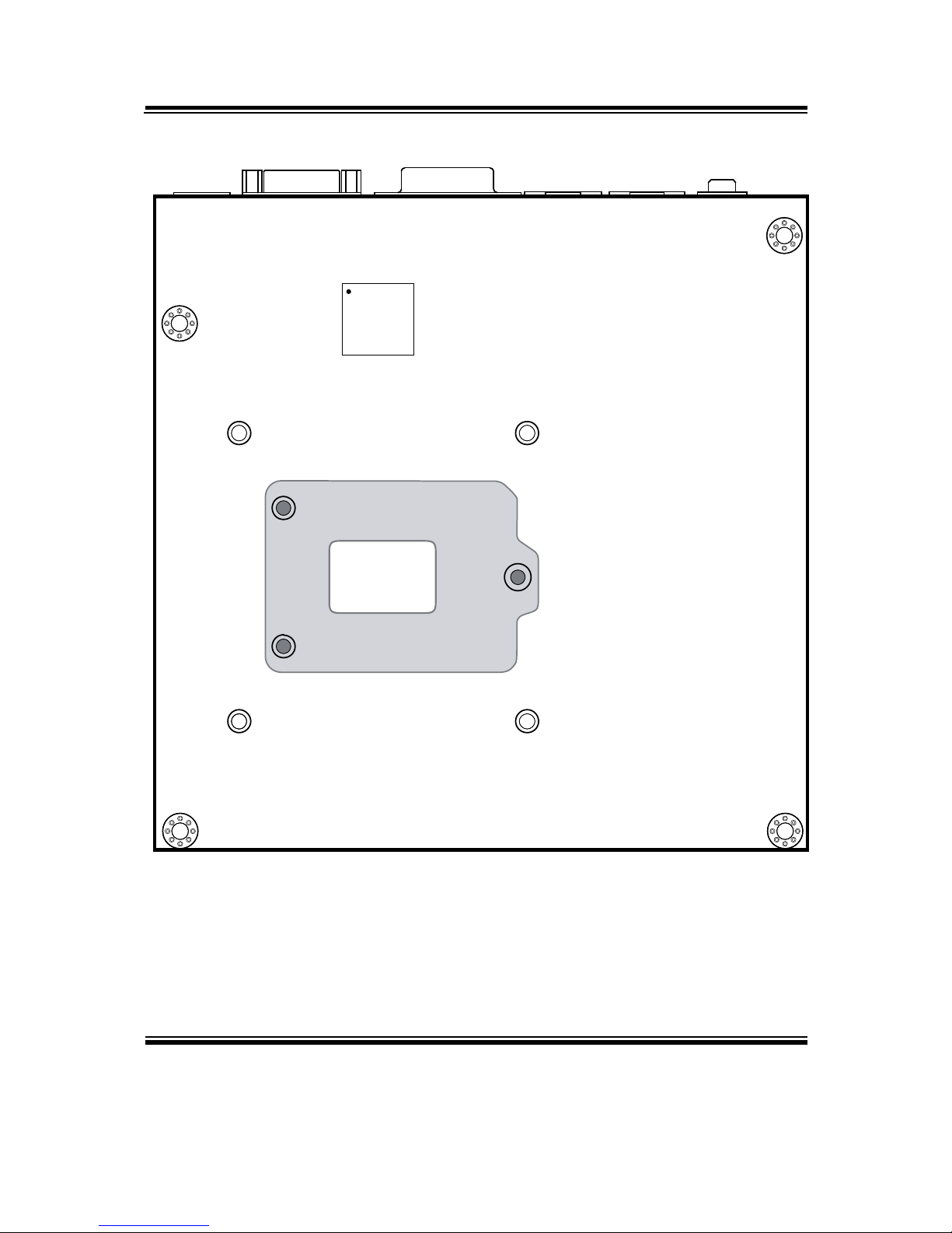
BM-0947 Rear Component locations
Page 15
Chapter 2 Hardware Configuration
BM-0947 USER′S MANUAL
Page: 2-5
2-3. HOW TO SET JUMPERS
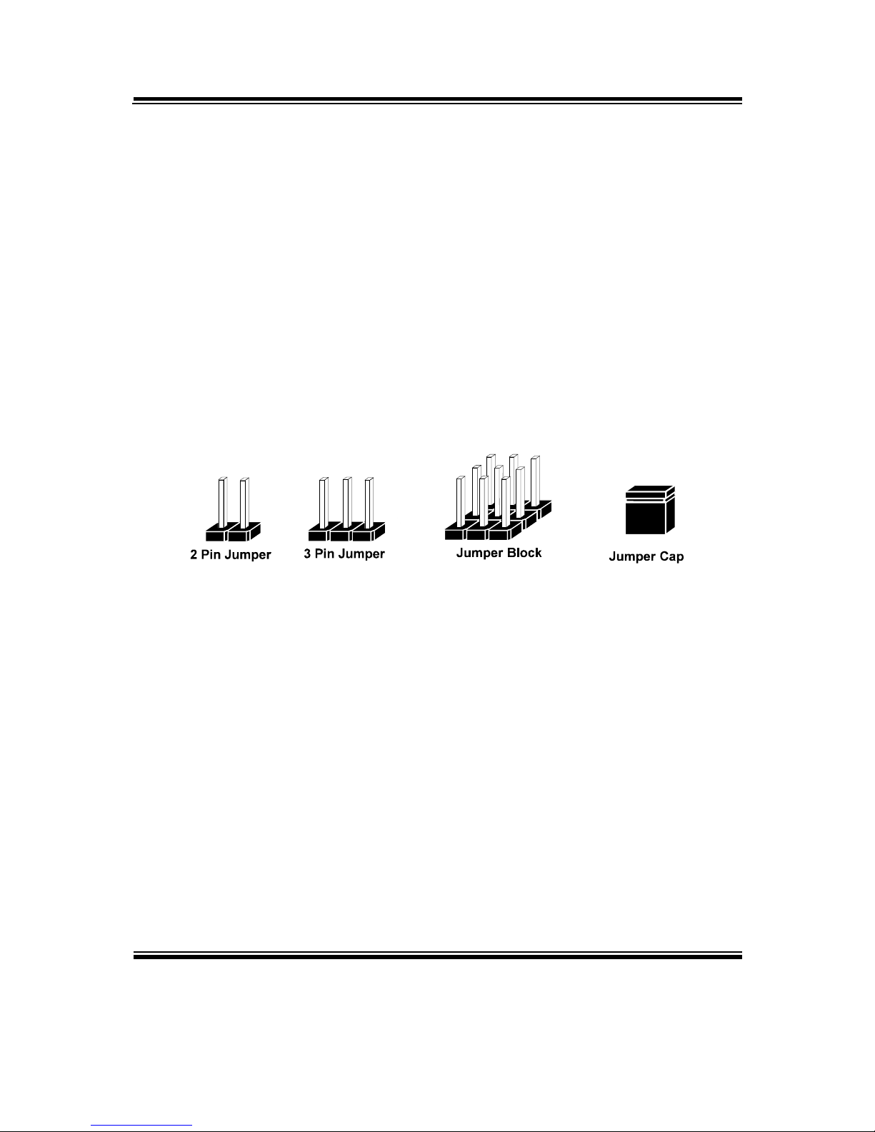
You can configure your board by setting jumpers. Jumper is consists of two or three metal
pins with a plastic base mounted on the card, and by using a small plastic "cap", Also
known as the jumper cap (with a metal contact inside), you are able to connect the pins.
So you can set-up your hardware configuration by "open" or "close" pins.
The jumper can be combined into sets that called jumper blocks. When the jumpers are all
in the block, you have to put them together to set up the hardware configuration. The figure
below shows how this looks like.
JUMPERS AND CAPS
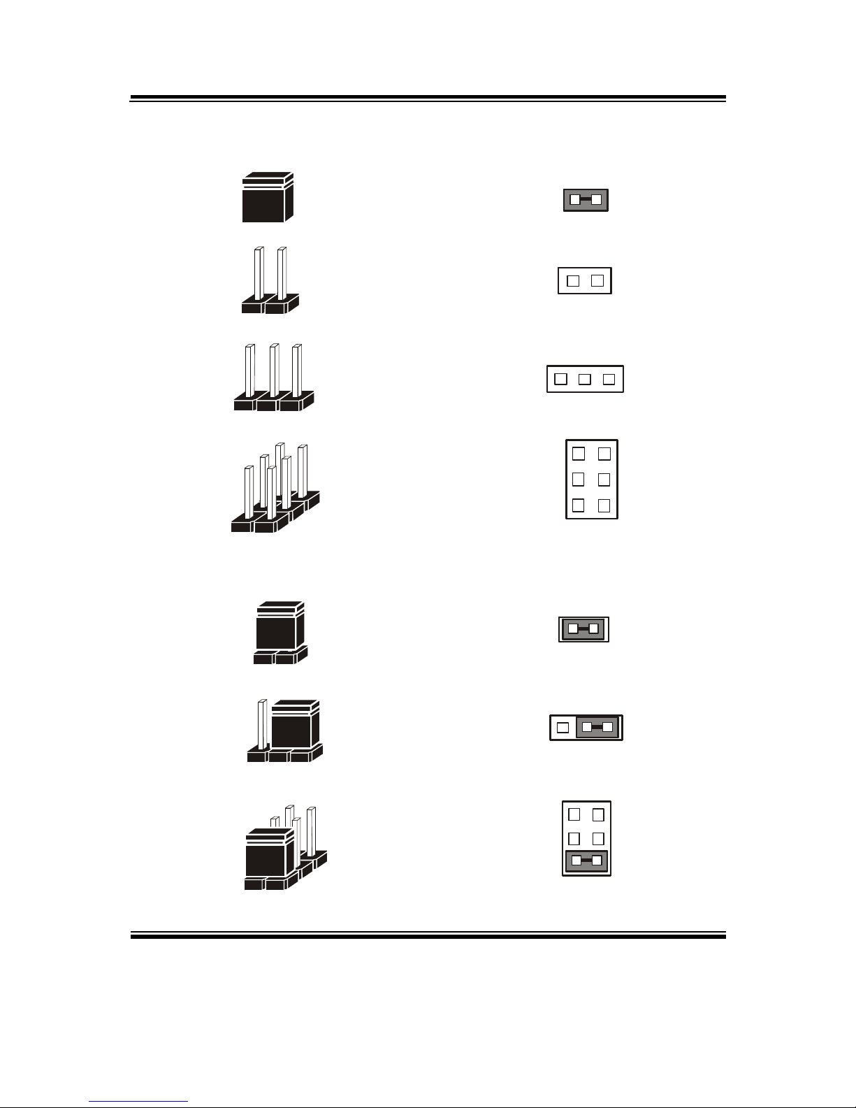
If a jumper has three pins (for examples, labelled PIN1, PIN2, and PIN3), You can connect
PIN1 & PIN2 to create one setting by shorting. You can either connect PIN2 & PIN3 to
create another setting. The same jumper diagrams are applied all through this manual. The
figure below shows what the manual diagrams look and what they represent.
Page 16
Chapter 2 Hardware Configuration
BM-0947 USER′S MANUAL
Page: 2-6
Jumper Diagrams
2 pin Jumper
looks like this
Jumper Cap
looks like this
3 pin Jumper
looks like this
Jumper Block
looks like this
Jumper Settings
Looks like this
3 pin Jumper
2-3 pin close(enabled)
Looks like this
Jumper Block
1-2 pin close(enabled)
2 pin Jumper close(enabled)
1
1
1
2
1 2
1
1
Looks like this
Page 17
Chapter 2 Hardware Configuration
BM-0947 USER′S MANUAL
Page: 2-7
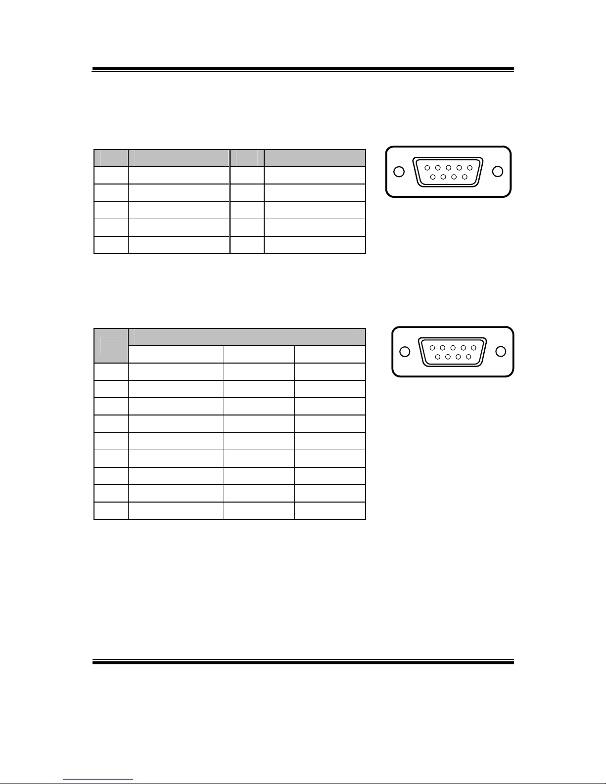
2-4. COM PORT
COM1, COM5: COM Port, fixed as RS-232
PIN ASSIGNMENT PIN ASSIGNMENT
1 DCD# 6 DSR#
2 RX 7 RTS#
3 TX 8 CTS#
4 DTR# 9 RI#
5 GND
COM2: COM2 Connector, selectable as RS-232/422/485
Co-lay with the other COM port stacked over COM1.
ASSIGNMENT
PIN
RS-232 RS-422 RS-485
1 DCD# TX- RS-485-
2 RX TX+ RS-485+
3 TX RX+ X
4 DTR# RX- X
5 GND GND GND
6 DSR# X X
7 RTS# X X
8 CTS# X X
9 RI# X X
5
1
9
6
COM1/
COM5
/
5
1
9
6
COM2
Page 18
Chapter 2 Hardware Configuration
BM-0947 USER′S MANUAL
Page: 2-8
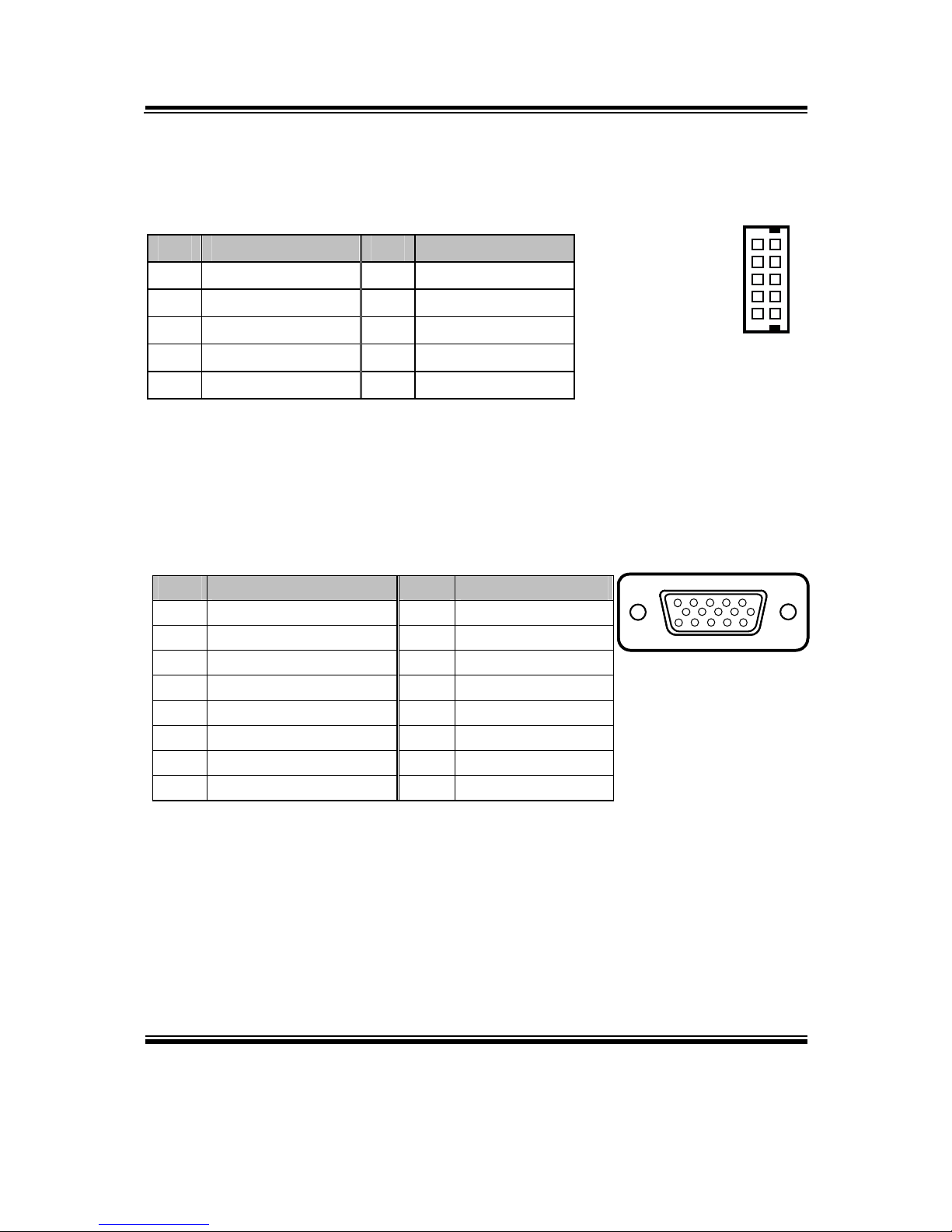
2-5. COM CONNECTOR
COM3, COM4, COM6: COM3 & COM4 Connectors, fixed as RS-232
PIN ASSIGNMENT PIN ASSIGNMENT
1 DCD# 6 DSR#
2 RX 7 RTS#
3 TX 8 CTS#
4 DTR# 9 RI#
5 GND 10 NC
2-6. VGA PORT
VGA1: VGA Port
PIN ASSIGNMENT PIN ASSIGNMENT
1 RED 9 VCC5
2 GREEN1 10 GND
3 BLUE 11 NC
4 NC 12 DDC_DATA
5 GND 13 HSYNC
6 GND 14 VSYNC
7 GND 15 DDC_CLK
8 GND
1
6
5
10
COM3/
COM4/
COM6/
15
610
1115
VGA1
Page 19
Chapter 2 Hardware Configuration
BM-0947 USER′S MANUAL
Page: 2-9
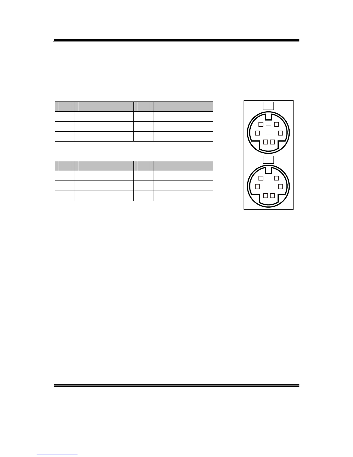
2-7. KEYBOARD & MOUSE PORT
KB_MS1: PS/2 Keyboard & Mouse Port
Keyboard:
PIN ASSIGNMENT PIN ASSIGNMENT
1 KBDATA 4 VCC5
2 NC 5 KBCLK
3 GND 6 NC
Mouse:
PIN ASSIGNMENT PIN ASSIGNMENT
7 MSDATA 10 VCC5
8 NC 11 MSCLK
9 GND 12 NC
3
12
4
56
9
78
10
1112
MS
KB
KB_MS1
Page 20
Chapter 2 Hardware Configuration
BM-0947 USER′S MANUAL
Page: 2-10
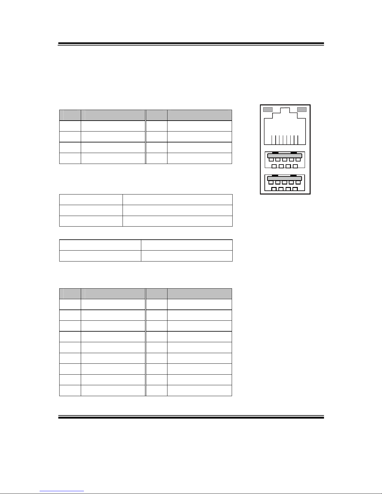
2-8. LAN & USB3.0 PORT
LAN1_USB1: LAN & Two USB3.0 Ports
LAN1 signal:
PIN ASSIGNMENT PIN ASSIGNMENT
1 MDI_0P 5 MDI_2N
2 MDI_0N 6 MDI_1N
3 MDI_1P 7 MDI_3P
4 MDI_2P 8 MDI_3N
LAN LED Indicator:
Left Side LED
Green Color On 10/100 LAN Speed Indicator
Orange Color On Giga LAN Speed Indicator
Off No LAN switch/hub connected.
Right Side LED
Yellow Color Blinking LAN Message Active
Off No LAN Message Active
USB3.0 signal:
PIN ASSIGNMENT PIN ASSIGNMENT
A1 VCC5 B1 VCC5
A2 USBP0N B2 USBP1N
A3 USBP0P B3 USBP1P
A4 GND B4 GND
A5 RX1_DN B5 RX2_DN
A6 RX1_DP B6 RX2_DP
A7 GND B7 GND
A8 TX1_DN B8 TX2_DN
A9 TX1_DP B9 TX2_DP
Green/Orange Yellow
B1 B4
B9 B5
A1 A4
A9 A5
8 1
LAN1_USB1
Page 21
Chapter 2 Hardware Configuration
BM-0947 USER′S MANUAL
Page: 2-11
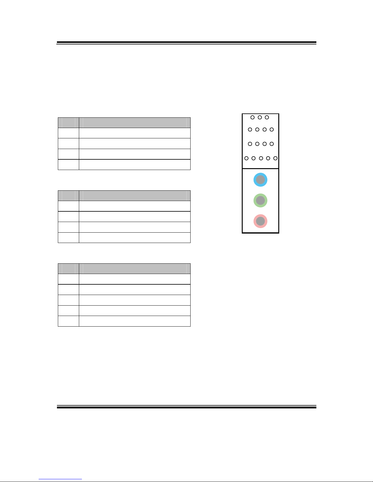
2-9. AUDIO JACK
AUDIO1: Line-In, Line-Out & Microphone
The connector can also support only Microphone.
Line-In:
PIN ASSIGNMENT
32 HD_LINE-IN-L
33 GND
34 GND
35 HD_LINE-IN-R
Line-Out:
PIN ASSIGNMENT
22 LINE-OUT-L
23 GND
24 GND
25 LINE-OUT-R
Mic-In:
PIN ASSIGNMENT
1 GND
2 HD_MIC1-L_L
3 GND
4 GND
5 HD_MIC1-R_L
1 2345
22232425
32333435
424344
AUDIO1
Page 22
Chapter 2 Hardware Configuration
BM-0947 USER′S MANUAL
Page: 2-12
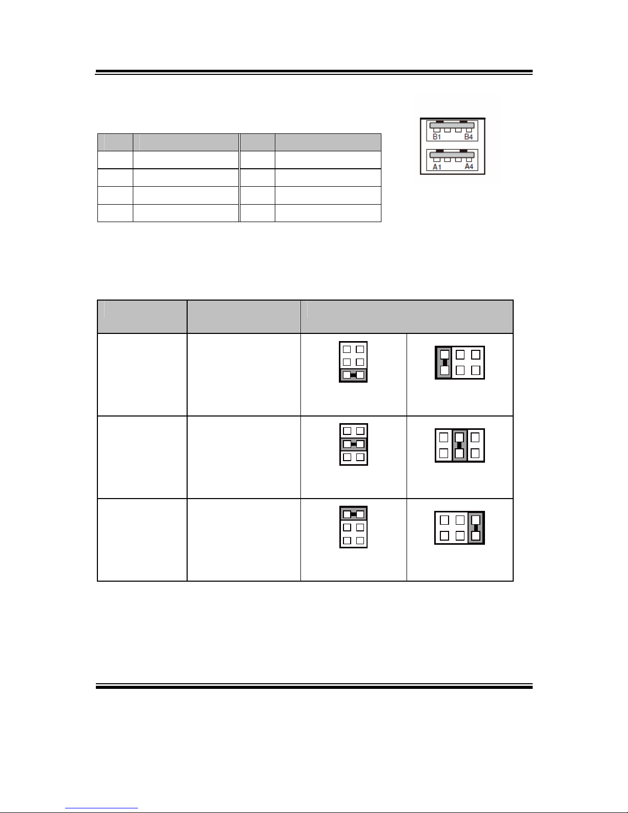
2-10. USB 2.0 Port
JUSB2: USB connectors
PIN ASSIGNMENT PIN ASSIGNMENT
A1 VCC5 B1 VCC5
A2 USBP2N B2 USBP3N
A3 USBP2P B3 USBP3P
A4 GND B4 GND
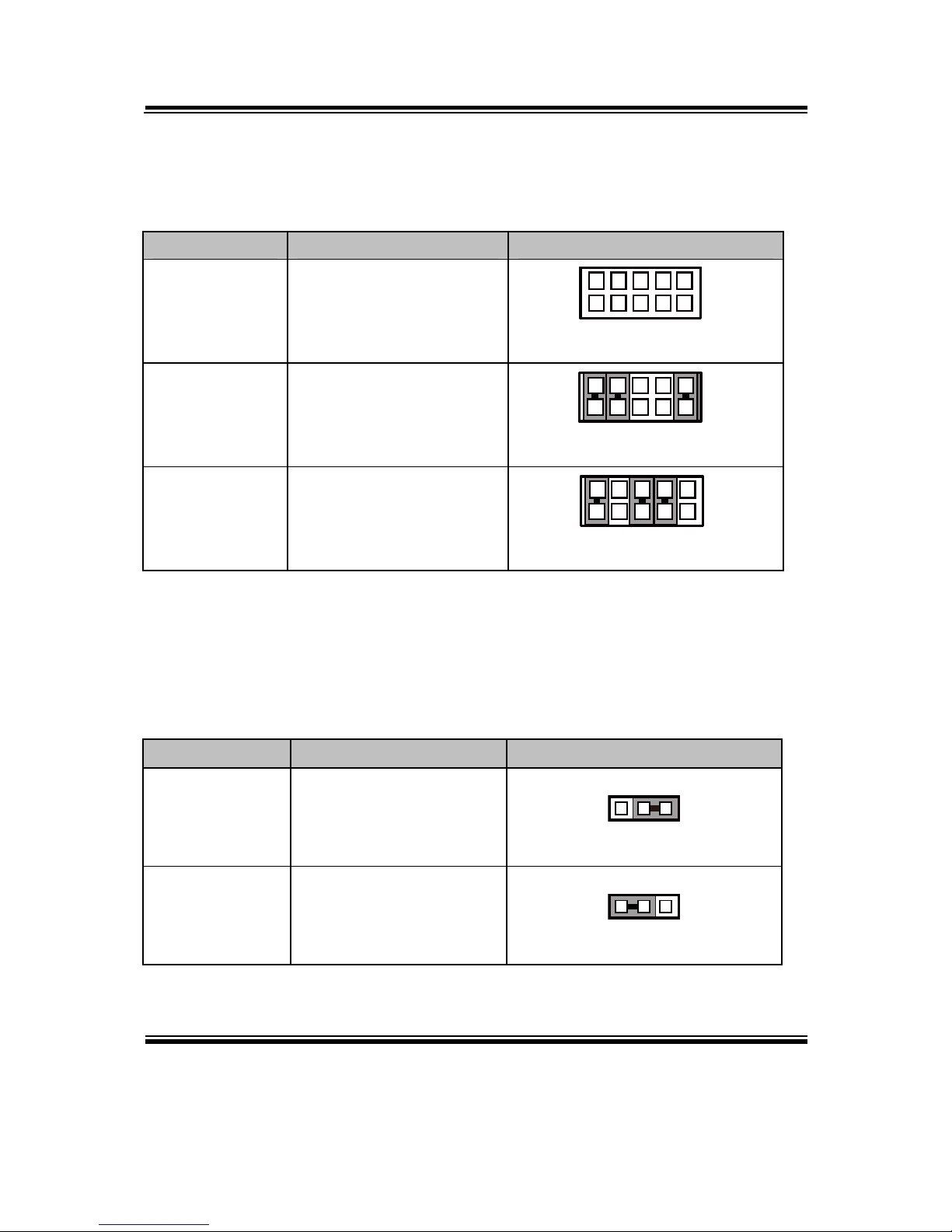
2-11.COM PORT RI & VOLTAGE SELECTION
JPCOM1 & JPCOM2: COM1 & COM2 Ports RI & Voltage Selection
SELECTION
JUMPTER
SETTING
JUMPER ILLUSTRATION
RI 1-2
5
6
1
2
JP_COM1
5
6
1
2
JP_COM2
12V 3-4
5
6
1
2
JP_COM1
5
6
1
2
JP_COM2
5V 5-6
5
6
1
2
JP_COM1
5
6
1
2
JP_COM2
Note: Manufacturing default is RI.
JUSB2
Page 23
Chapter 2 Hardware Configuration
BM-0947 USER′S MANUAL
Page: 2-13
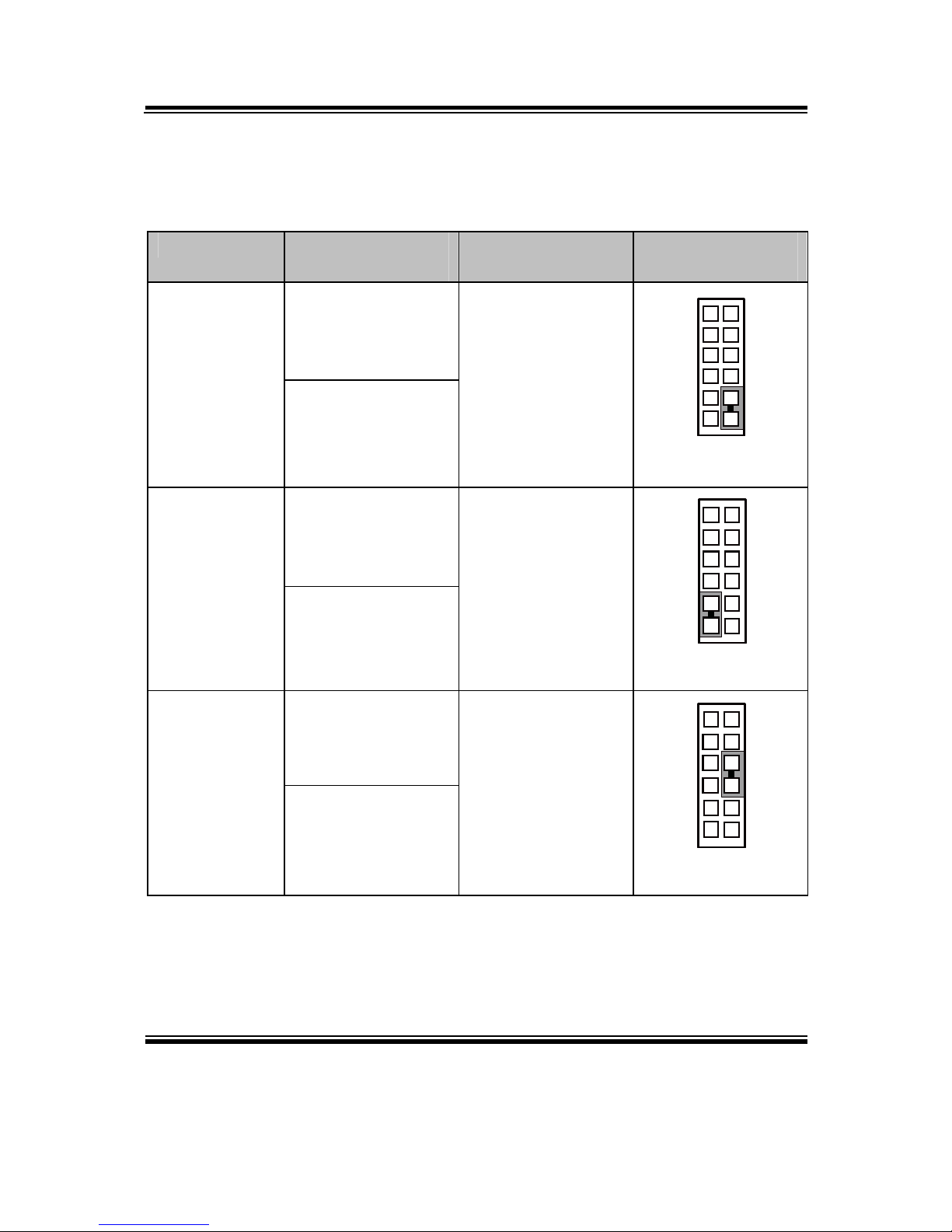
2-12. COM2 RS-232/422/485 SELECTION
JP8: RS-232/422/485 (COM2) Selection Connector, used to set COM2 function.
SELECTION JUMPER SETTINGS JUMPER ILLUSTRATION
RS-232 All Open
10
9
2
1
JP8
RS-422
1-2,
3-4,
9-10
10
9
2
1
JP8
RS-485
1-2,
5-6,
7-8
10
9
2
1
JP8
Note: Manufacturing default is RS-232.
2-13. COM2 AUTO-DETECT SELECTION
JP7: COM2 Auto-detect Selection
SELECTION JUMPER SETTINGS JUMPER ILLUSTRATION
Normal 1-2
3
1
JP7
Auto Gating 2-3
3
1
JP7
Note: Manufacturing default is Normal.
Page 24
Chapter 2 Hardware Configuration
BM-0947 USER′S MANUAL
Page: 2-14
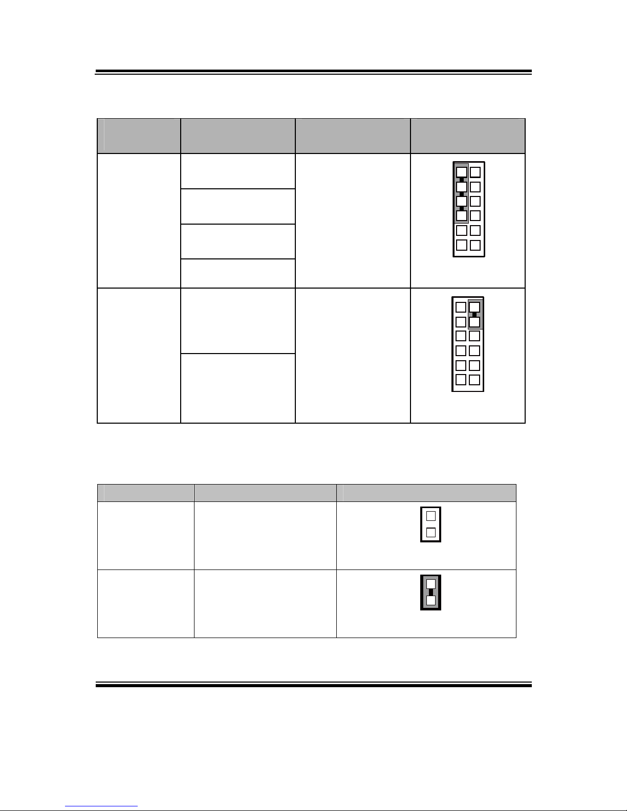
2-14. FRONT PANEL CONNECTOR & SELECTION
FP1: Front Panel Connector
SELECTION
PIN &
ASSIGNMENT
JUMPER
SETTINGS
JUMPER
ILLUSTRATION
1. HDD_LED+
HDD LED
3. HDD_LED-
1-3
12 1
1
2 1
FP1
2. PWR_LED+
Power LED
4. PWR_LED-
2-4
12 1
1
2 1
FP1
5. GND
Reset Button
7. RST_BTN
5-7
12 1
1
2 1
FP1
Page 25
Chapter 2 Hardware Configuration
BM-0947 USER′S MANUAL
Page: 2-15
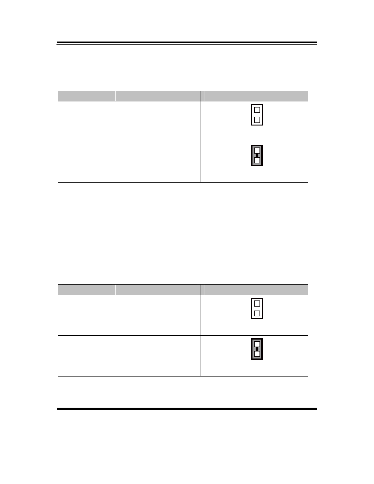
2-15. INTEL
®
ME SELECTION
JP3: Intel® ME Selection
SELECTION JUMPER SETTINGS JUMPER ILLUSTRATION
Normal Open
1
JP3
ME Disabled Close
1
JP3
Note: Manufacturing Default is Normal.
SELECTIO
N
PIN &
ASSIGNMENT
JUMPER
SETTINGS
JUMPER
ILLUSTRATION
6. SPK_VCC
8. Speaker signal
10. Speaker signal
External
Speaker
12. Speaker signal
6-8-10-12
12 1
1
2 1
FP1
9. GND
ATX Power
Button
11. PWRBTNSW
9-11
1211
2 1
FP1
Page 26
Chapter 2 Hardware Configuration
BM-0947 USER′S MANUAL
Page: 2-16
2-16. CLEAR CMOS DATA SELECTION
JP4: Clear CMOS Data Selection
SELECTION JUMPER SETTINGS JUMPER ILLUSTRATION
Normal Open
1
JP4
Clear CMOS* Close
1
JP4
Note: Manufacturing Default is Normal.
*To clear CMOS data, user must power-off the computer and set the jumper to “Clear
CMOS” as illustrated above. After five to six seconds, set the jumper back to
“Normal” and power-on the computer.
2-17. BIOS RECOVERY MODE SELECTION
JP1: BIOS Recovery Mode Selection
SELECTION JUMPER SETTINGS JUMPER ILLUSTRATION
Recovery Open
1
JP1
Normal Close
1
JP1
Note: Manufacturing Default is Normal.
Page 27
Chapter 2 Hardware Configuration
BM-0947 USER′S MANUAL
Page: 2-17
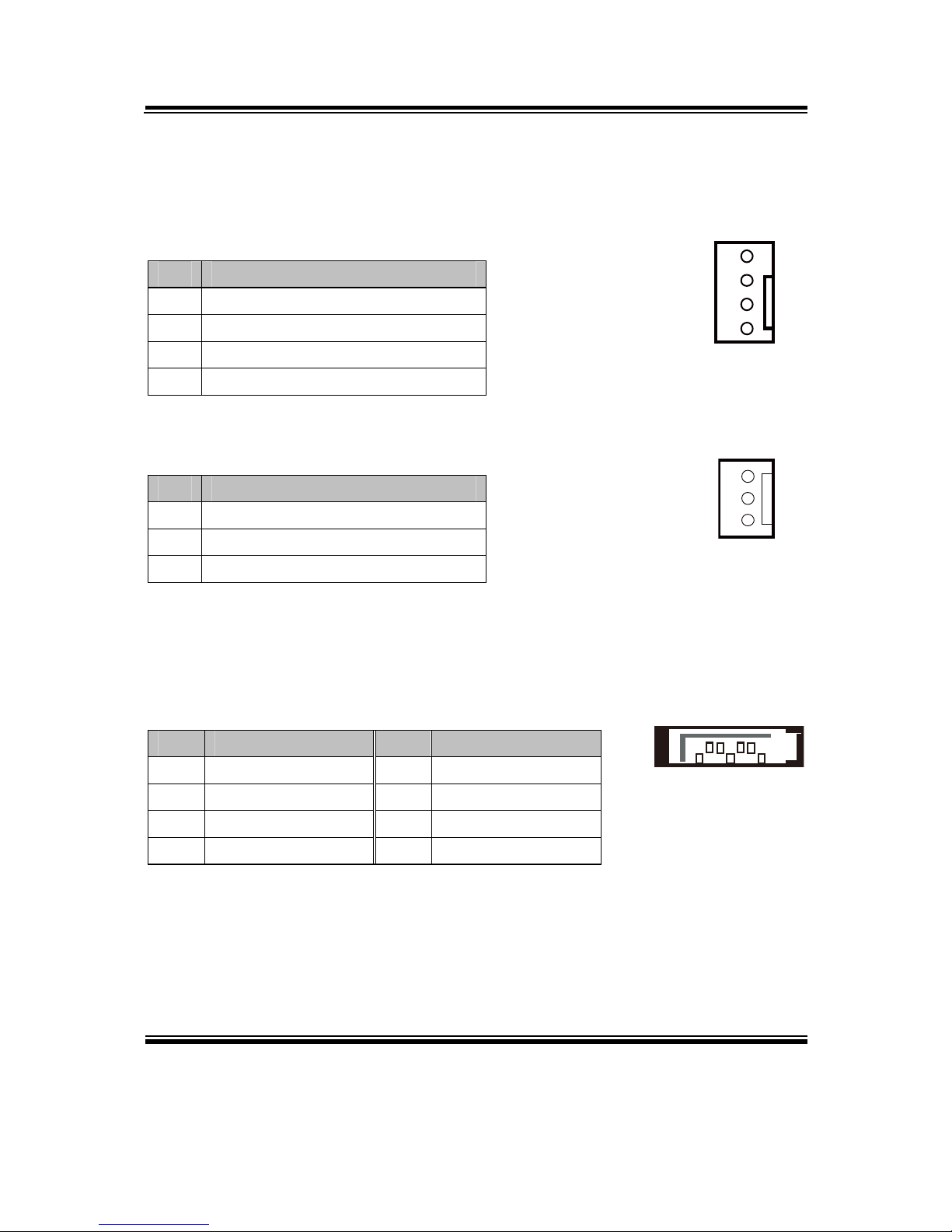
2-18. FAN CONNECTOR
CPU_FAN1: CPU Fan Connector
SYS_FAN1: System Fan Connector
PIN ASSIGNMENT
1 GND
2 VCC12
3 TAC
4 CTL
SYS_FAN2: System Fan Connector
PIN ASSIGNMENT
1 GND
2 VCC12
3 NC
2-19. SATA CONNECTOR
SATA1, SATA2, SATA3: Three Serial ATA Connectors
PIN ASSIGNMENT PIN ASSIGNMENT
1 GND 5 RXNC
2 TXPC 6 RXPC
3 TXNC 7 GND
4 GND
4
1
CPU_FAN1/
SYS_FAN1/
1
3
SYS_FAN2
17
SATA1/
SATA2/
SATA3/
Page 28
Chapter 2 Hardware Configuration
BM-0947 USER′S MANUAL
Page: 2-18
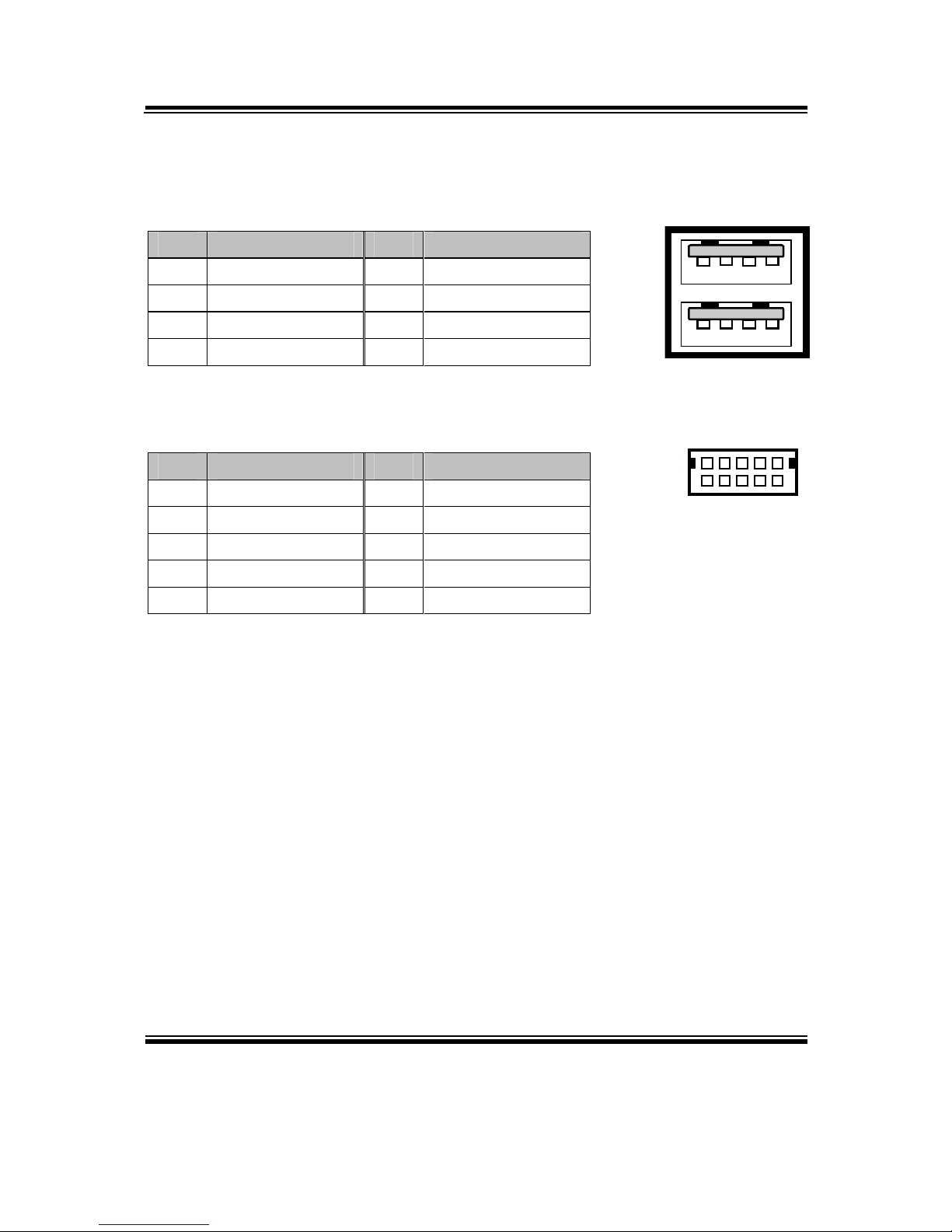
2-20. USB2.0 PORT
JUSB2: Two stacked USB2.0 Ports
PIN ASSIGNMENT PIN ASSIGNMENT
A1 VCC5 B1 VCC5
A2 USBP2N B2 USBP3N
A3 USBP2P B3 USBP3P
A4 GND B4 GND
USB3, USB4: USB2.0 Connectors
PIN ASSIGNMENT PIN ASSIGNMENT
1 VCC5 6 USBP
2 VCC5 7 GND
3 USBN 8 GND
4 USBN 9 NC
5 USBP 10 GND
2
1
9
10
USB3/
USB4/
A4A1
B4B1
JUSB2
Page 29
Chapter 2 Hardware Configuration
BM-0947 USER′S MANUAL
Page: 2-19
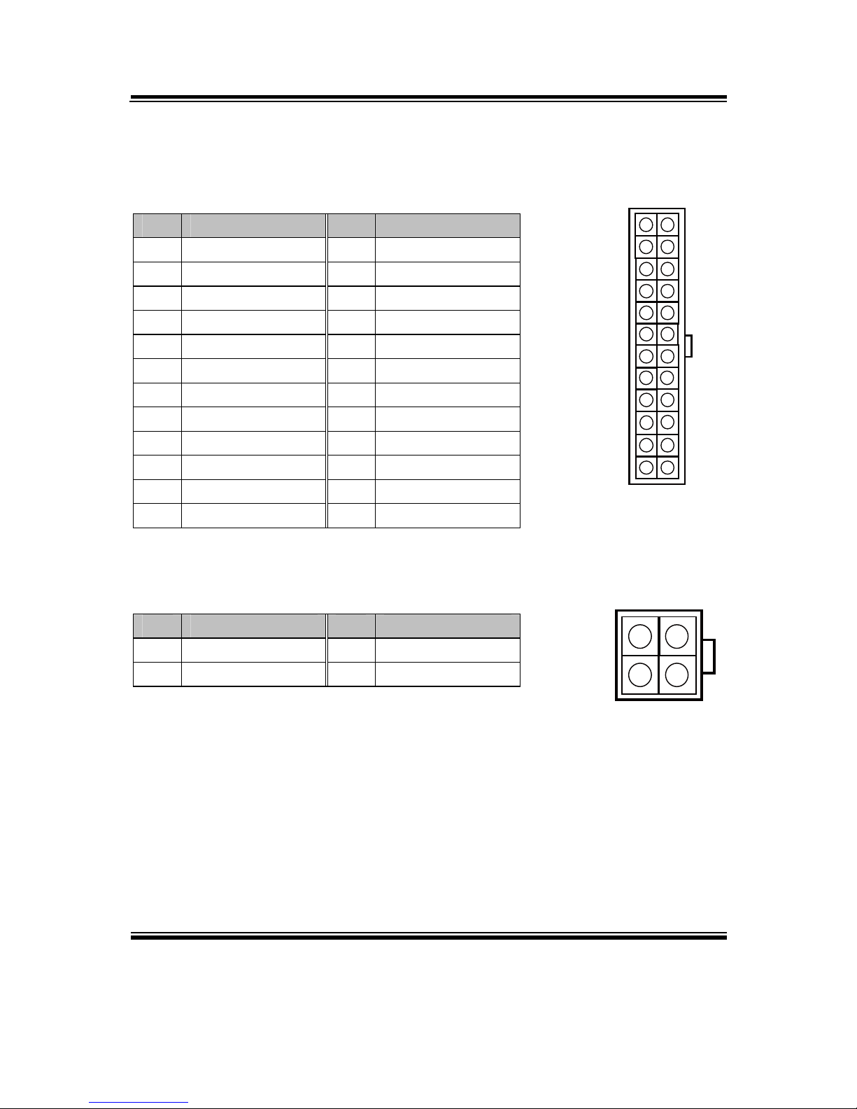
2-21. ATX POWER CONNECTOR
ATX_PWR1: ATX Power Connector
PIN ASSIGNMENT PIN ASSIGNMENT
1 +3.3V 13 +3.3V
2 +3.3V 14 -12V
3 GND 15 GND
4 +5V 16 PSON
5 GND 17 GND
6 +5V 18 GND
7 GND 19 GND
8 POK 20 -5V
9 5VSB 21 +5V
10 +12V 22 +5V
11 +12V 23 +5V
12 +3.3V 24 GND
ATX_PWR2: ATX Power Connector
PIN ASSIGNMENT PIN ASSIGNMENT
1 GND 3 +12V
2 GND 4 +12V
1 13
12
24
ATX_PWR1
1
2
3
4
ATX_PWR2
Page 30
Chapter 2 Hardware Configuration
BM-0947 USER′S MANUAL
Page: 2-20
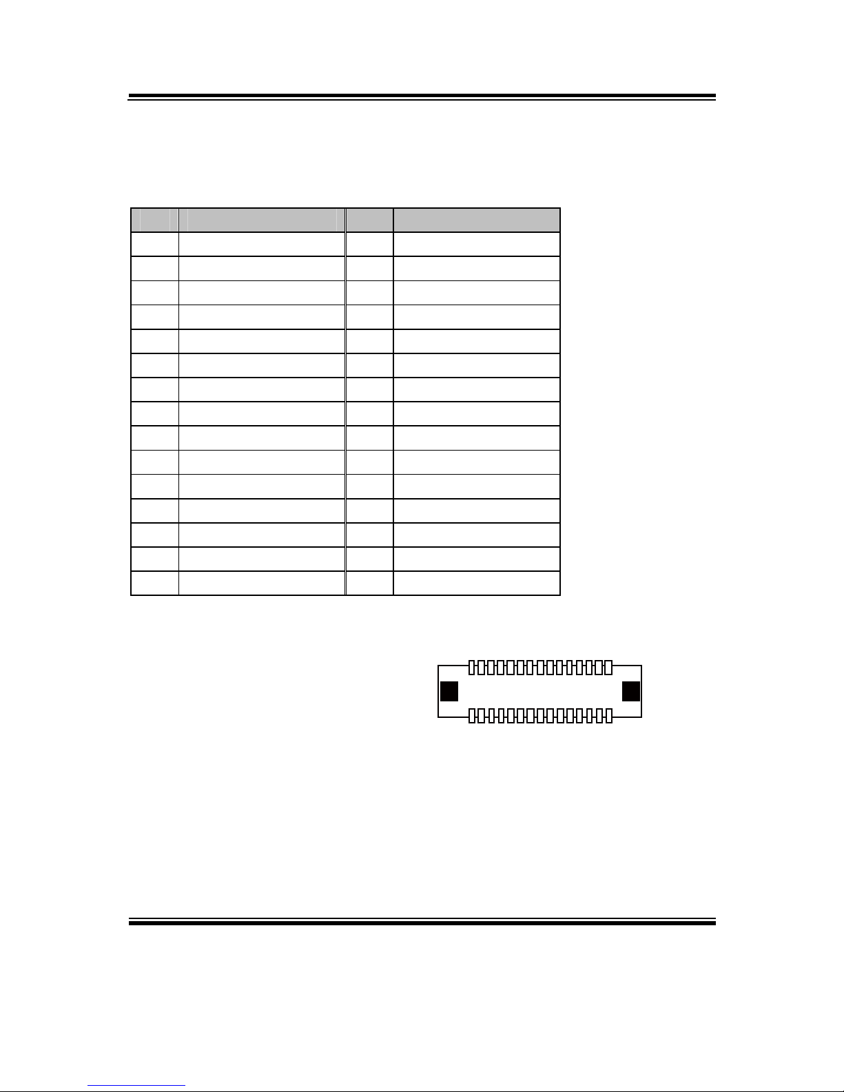
2-22. LVDS CONNECTOR
LVDS1: LVDS Connector
PIN ASSIGNMENT PIN ASSIGNMENT
1 LVDS1_VCC 16 LVDS1_CLKA_DP
2 GND 17 LVDS1_CLKA_DN
3 LVDS1_CLKB_DN 18 GND
4 LVDS1_CLKB_DP 19 LVDS1_A2_DP
5 GND 20 LVDS1_A2_DN
6 LVDS1_B2_DN 21 GND
7 LVDS1_B2_DP 22 LVDS1_A1_DP
8 GND 23 LVDS1_A1_DN
9 LVDS1_B1_DN 24 GND
10 LVDS1_B1_DP 25 LVDS1_A0_DP
11 LVDS1_B3_DP 26 LVDS1_A0_DN
12 LVDS1_B3_DN 27 LVDS1_A3_DP
13 LVDS1_B0_DP 28 LVDS1_A3_DN
14 LVDS1_B0_DN 29 LVDS1_VCC
15 GND 30 LVDS1_VCC
2
1 29
30
LVDS1
Page 31
Chapter 2 Hardware Configuration
BM-0947 USER′S MANUAL
Page: 2-21
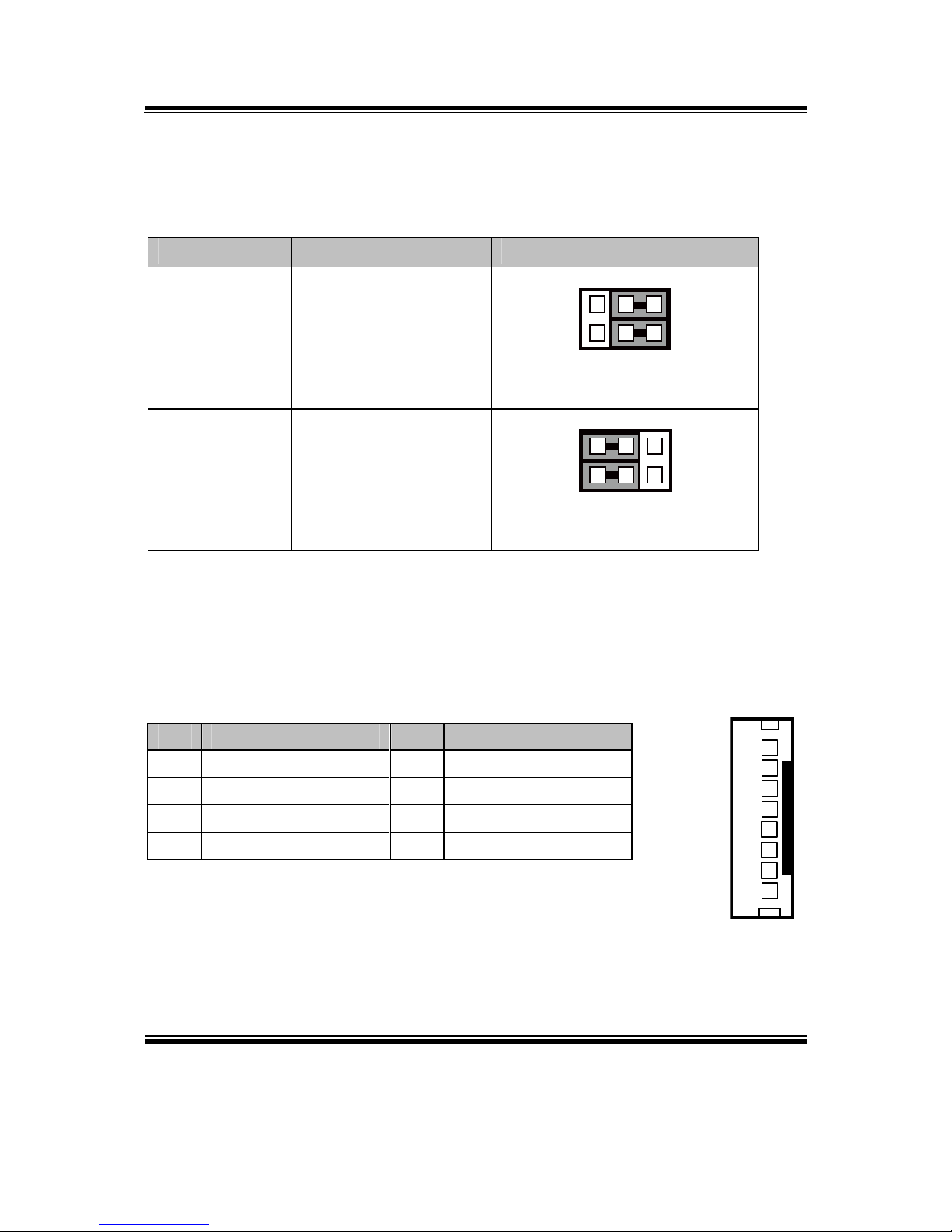
2-23. LVDS VOLTAGE SELECTION
JP15: LVDS Voltage Selection
SELECTION JUMPER SETTING JUMPER ILLUSTRATION
3.3V
1-3,
2-4
2
1
6
5
JP15
5V
3-5,
4-6
216
5
JP15
Note: Manufacturing default is 3.3V.
2-24. LCD BACKLIGHT CONNECTOR
JINV1: LCD Backlight Connector
PIN ASSIGNMENT PIN ASSIGNMENT
1 GND 5 GND
2 +12V 6 PWM
3 +12V 7 GND
4 +12V 8 Enable
1
8
JINV1
Page 32

Page: 3-1
SOFTWARE
UTILITIES
This chapter comprises the detailed information of VGA driver, LAN
driver, and Sound driver.
Sections included:
Introduction.
Intel® Chipset Software Installation Utility
Intel® USB3.0 eXtensible Host Controller Utility
Intel® Management Engine Components Utility
VGA Driver Utility
LAN Driver Utility
Sound Driver Utility
CHAPTER
3
Page 33

Chapter 3 Software Utilities
BM-0947 USER′S MANUAL
Page:3-2
3-1. INTRODUCTION
Enclosed with our BM-0947 package are our driver utilities, which come in a format
of CD ROM. Refer to the following table for driver locations: and go to the
corresponding folder for the chipset Intel® H81 or Intel® Q87:
For Intel® H81:
FILENAME (Assume that CD ROM drive is D:) PURPOSE
D:\H81\Driver\Plaform\Win7,Win8(32-bit)\Main Chip
D:\H81\Driver\Plaform\Win7,Win8(64-bit)\Main Chip
Intel® Chipset Device
Software installer
D:\H81\Driver\Plaform\Win7,Win8(32-bit)\USB3.0
D:\H81\Driver\Plaform\Win7,Win8(64-bit)\USB3.0
Intel
®
USB3.0 eXtensible
host controller
D:\H81\Driver\Plaform\Win7,Win8(32-bit)\ME
D:\H81\Driver\Plaform\Win7,Win8(64-bit)\ME
Intel® Management
Engine Components
installer
D:\H81\Driver\Plaform\Win7,Win8(32-bit)\COM
D:\H81\Driver\Plaform\Win7,Win8(64-bit)\COM
Patch files for COM
ports
D:\H81\Driver\Plaform\Win7,Win8(32-bit)\VGA
D:\H81\Driver\Plaform\Win7,Win8(64-bit)\VGA
Intel® HD Graphics
installer
D:\H81\Driver\Plaform\Win7,Win8(32-bit)\LAN
D:\H81\Driver\Plaform\Win7,Win8(64-bit)\LAN
Intel(R) Network
Connections Software
D:\H81\Driver\Plaform\Win7,Win8(32-bit)\Sound
D:\H81\Driver\Plaform\Win7,Win8(64-bit)\Sound
Realtek High Definition
Audio System Software
D:\H81\Driver\Flash BIOS BIOS update utility
Note: Be sure to install the Utility right after the OS fully installed.
Page 34

Chapter 3 Software Utilities
BM-0947 USER′S MANUAL
Page:3-3
For Intel® Q87:
FILENAME (Assume that CD ROM drive is D:) PURPOSE
D:\Q87\Driver\Plaform\Win7,Win8(32-bit)\Main Chip
D:\Q87\Driver\Plaform\Win7,Win8(64-bit)\Main Chip
Intel® Chipset Device
Software installer
D:\Q87\Driver\Plaform\Win7,Win8(32-bit)\USB3.0
D:\Q87\Driver\Plaform\Win7,Win8(64-bit)\USB3.0
Intel® USB3.0 eXtensib
le
host controller
D:\Q87\Driver\Plaform\Win7,Win8(32-bit)\ME
D:\Q87\Driver\Plaform\Win7,Win8(64-bit)\ME
Intel® Management
Engine Components
installer
D:\Q87\Driver\Plaform\Win7,Win8(32-bit)\COM
D:\Q87\Driver\Plaform\Win7,Win8(64-bit)\COM
Patch files for COM
ports
D:\Q87\Driver\Plaform\Win7,Win8(32-bit)\VGA
D:\Q87\Driver\Plaform\Win7,Win8(64-bit)\VGA
Intel® HD Graphics
installer
D:\Q87\Driver\Plaform\Win7,Win8(32-bit)\LAN
D:\Q87\Driver\Plaform\Win7,Win8(64-bit)\LAN
Intel(R) Network
Connections Software
D:\Q87\Driver\Plaform\Win7,Win8(32-bit)\Sound
D:\Q87\Driver\Plaform\Win7,Win8(64-bit)\Sound
Realtek High Definition
Audio System Software
D:\Q87\Driver\Flash BIOS BIOS update utility
Note: Be sure to install the Utility right after the OS fully installed.
Page 35

Chapter 3 Software Utilities
BM-0947 USER′S MANUAL
Page:3-4
3-2. INTEL® CHIPSET DEVICE SOFTWARE INSTALLER
3-2-1. Introduction
The Intel® Chipset Device Software installs Windows INF files to the target system.
These files outline to the operating system how to configure the Intel® chipset
components in order to ensure that the following features function properly:
Core PCI and ISAPNP Services
PCIe Support
IDE/ATA33/ATA66/ATA100 Storage Support
SATA Storage Support
USB Support
Identification of Intel® Chipset Components in the Device Manager
3-2-2. Installation of Utility for Windows 7/8
The Utility Pack is to be installed only for Windows 7/8 series, and it should be
installed right after the OS installation. Please follow the steps below:
1. Insert the driver disk into a CD ROM device.
2. Under Windows system, go to the directory where the Utility driver is located.
3. Run the application with administrative privileges.
Page 36

Chapter 3 Software Utilities
BM-0947 USER′S MANUAL
Page:3-5
3-3. INTEL® USB3.0 EXTENSIBLE HOST CONTROLLER
UTILITY
3-3-1. Introduction
Intel® USB 3.0 eXtensible Host Controller Driver supports the following Intel®
Chipsets/Processors:
4th Generation Intel® Core™ Processor Family
Intel® 8 Series/C220 Series Chipset Family
4th Generation U-Series Platform I/O
3-3-2. Installation Instructions for Windows 7/8
To install the utility, simply follow the following steps:
1. Insert the driver disk into a CD ROM device.
2. Under Windows system, go to the directory where the driver is located.
3. Run the application with administrative privileges.
Page 37

Chapter 3 Software Utilities
BM-0947 USER′S MANUAL
Page:3-6
3-4. INTEL® MANAGEMENT ENGINE COMPONENTS UTILITY
3-4-1. Introduction
The Intel® ME software components that need to be installed depend on the system's
specific hardware and firmware features. The installer, compatible with Windows 7/8
series, detects the system's capabilities and installs the relevant drivers and
applications.
3-4-2. Installation Instructions for Windows 7/8
To install the utility, simply follow the following steps:
1. Insert the driver disk into a CD ROM device.
2. Under Windows system, go to the directory where the driver is located.
3. Run the application with administrative privileges.
Page 38
Chapter 3 Software Utilities
BM-0947 USER′S MANUAL
Page:3-7
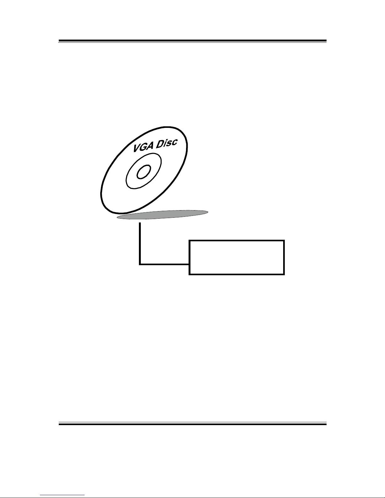
3-5. VGA DRIVER UTILITY
3-5-1. Introduction
The VGA interface embedded with our BM-0947 can support a wide range of display.
You can display DVI simultaneously with the same mode.
1. Win 7 Series
2. Win 8 Series
3-5-2. Installation of VGA Driver
To install the VGA Driver, simply follow the following steps:
1. Insert the driver disk into a CD ROM device.
2. Under Windows system, go to the directory where the VGA driver is located.
3. Run the application with administrative privileges..
Page 39
Chapter 3 Software Utilities
BM-0947 USER′S MANUAL
Page:3-8
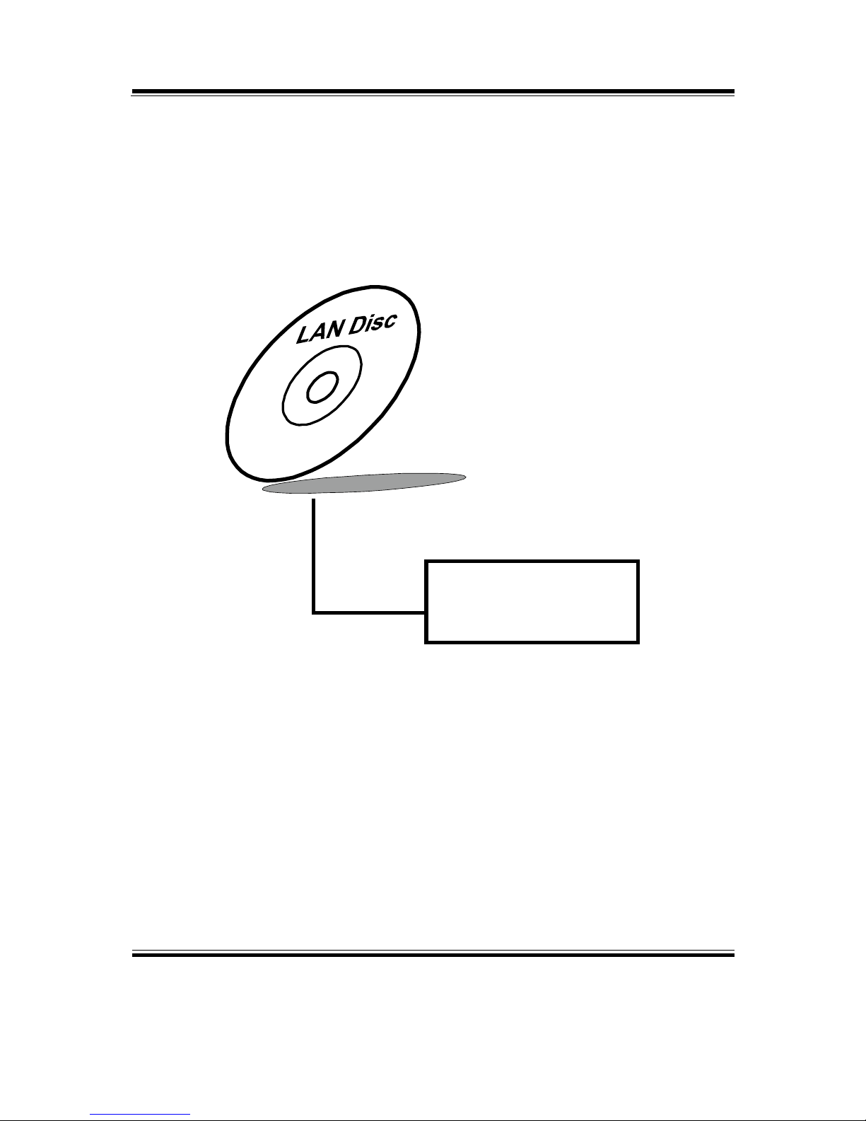
3-6. LAN DRIVER UTILITY
3-6-1. Introduction
BM-0947 is enhanced with LAN function that can support various network adapters.
Installation programs for LAN drivers are listed as follows:
1. Win 7 Series
2. Win 8 Series
For more details on Installation procedure, please refer to Readme.txt file found
on LAN Driver Utility.
Page 40
Chapter 3 Software Utilities
BM-0947 USER′S MANUAL
Page:3-9
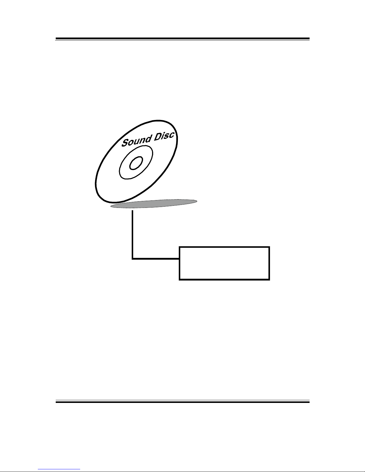
3-7. SOUND DRIVER UTILITY
3-7-1. Introduction
The Realtek sound function enhanced in this system is fully compatible with Windows
7/8. Below, you will find the content of the Sound driver:
1. Win 7 Series
2. Win 8 Series
3-7-2. Installation of Sound Driver
1. Insert the driver disk into a CD ROM device.
2. Under Windows system, go to the directory where the Sound driver is located.
3. Run the application with administrative privileges..
4. Follow the instructions on the screen to complete the installation.
5. Once the installation is completed, shut down the system and restart in order for
the changes to take effect.
Page 41

Page: 4-1
BIOS SETUP
This chapter shows how to set up the BIOS.
Sections included:
Introduction
Entering Setup
Main
Advanced
Chipset
Boot
Security
Save & Exit
CHAPTER
4
Page 42
Chapter 4 BIOS Setup
BM-0947 USER′S MANUAL
Page: 4-2
4-1. INTRODUCTION
The board BM-0947 (with Intel® H81) uses an AMI Aptio BIOS that is stored in the
Serial Peripheral Interface Flash Memory (SPI Flash) and can be updated. The SPI
Flash contains the BIOS Setup program, Power-on Self-Test (POST), the PCI autoconfiguration utility, LAN EEPROM information, and Plug and Play support.
Aptio is AMI’s BIOS firmware based on the UEFI (Unified Extensible Firmware
Interface) Specifications and the Intel Platform Innovation Framework for EFI. The
UEFI specification defines an interface between an operating system and platform
firmware. The interface consists of data tables that contain platform-related
information, boot service calls, and runtime service calls that are available to the
operating system and its loader. These provide standard environment for booting an
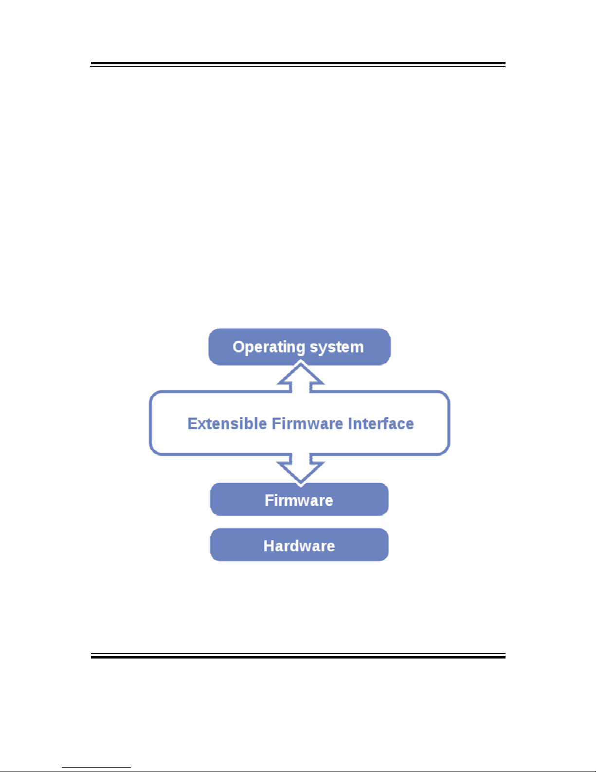
operating system and running pre-boot applications. Following illustration shows
Extensible Firmware Interface’s position in the software stack.
Page 43

Chapter 4 BIOS Setup
BM-0947 USER′S MANUAL
Page: 4-3
EFI BIOS provides an user interface allow users the ability to modify hardware
configuration, e.g. change system date and time, enable or disable a system component,
decide bootable device priorities, setup personal password, etc., which is convenient
for modifications and customization of the computer system and allows technicians
another method for finding solutions if hardware has any problems.
The BIOS Setup program can be used to view and change the BIOS settings for the
computer. The BIOS Setup program is accessed by pressing the <Del> or <ESC> key
after the POST memory test begins and before the operating system boot begins. The
settings are shown below.
Page 44

Chapter 4 BIOS Setup
BM-0947 USER′S MANUAL
Page: 4-4
4-2. ENTERING SETUP
When the system is powered on, the BIOS will enter the Power-On Self Test (POST)
routines and the following message will appear on the lower screen:
Version: 2.15.1226. Copyright (C) 2012 American Magatrends, Inc.
BIOS Date: 05/29/2014 10:09:57 Ver: M9470TH6
Press <DEL> or <F2> to enter setup.
POST screen
As long as this message is present on the screen you may press the <Del> key (the one
that shares the decimal point at the bottom of the number keypad) to access the Setup
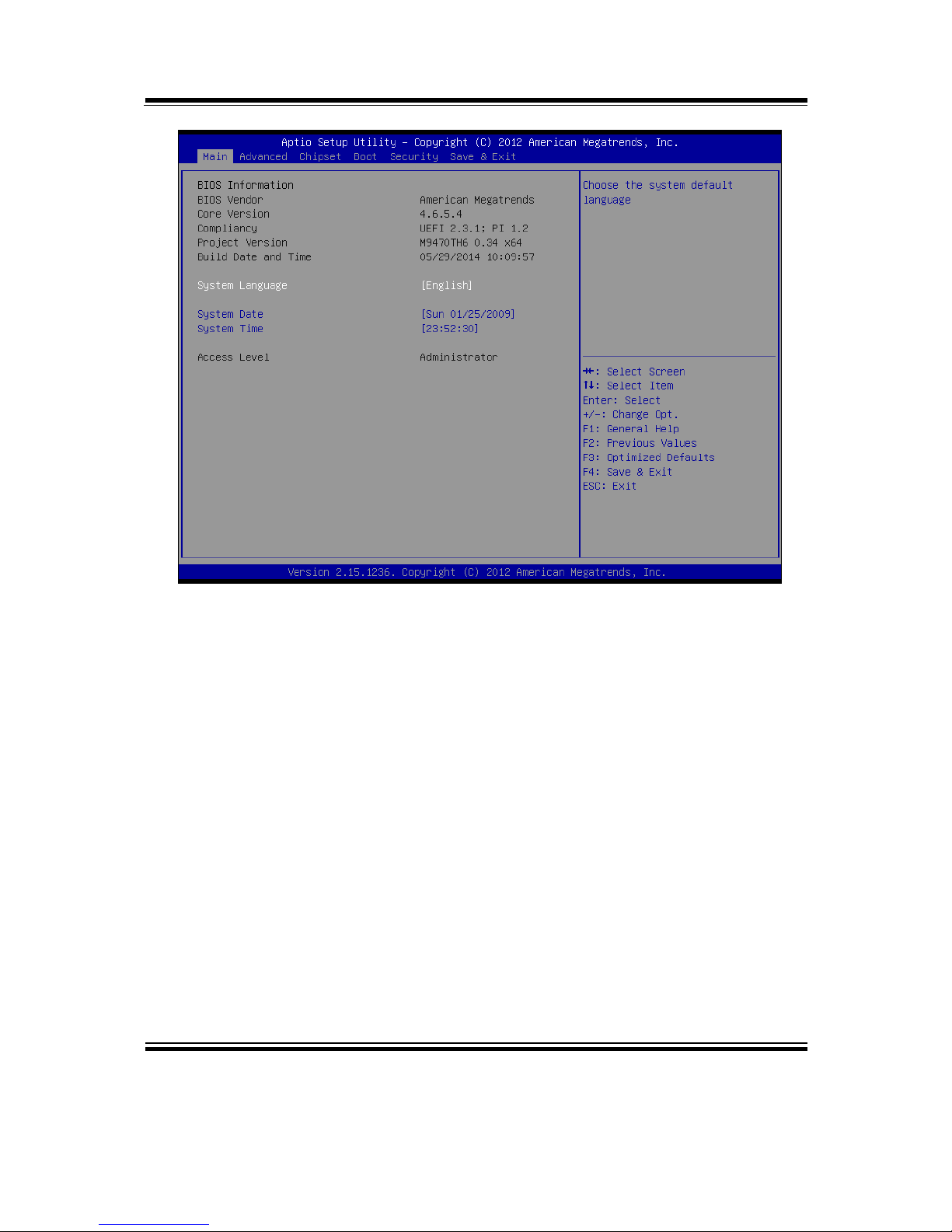
program. In a moment, the main menu of the Aptio Setup Utility will appear on the
screen:
Page 45
Chapter 4 BIOS Setup
BM-0947 USER′S MANUAL
Page: 4-5
BIOS setup program initial screen
You may move the cursor by up/down keys to highlight the individual menu items. As
you highlight each item, a brief description of the highlighted selection will appear at
the bottom of the screen.
Page 46
Chapter 4 BIOS Setup
BM-0947 USER′S MANUAL
Page: 4-6
4-3. MAIN
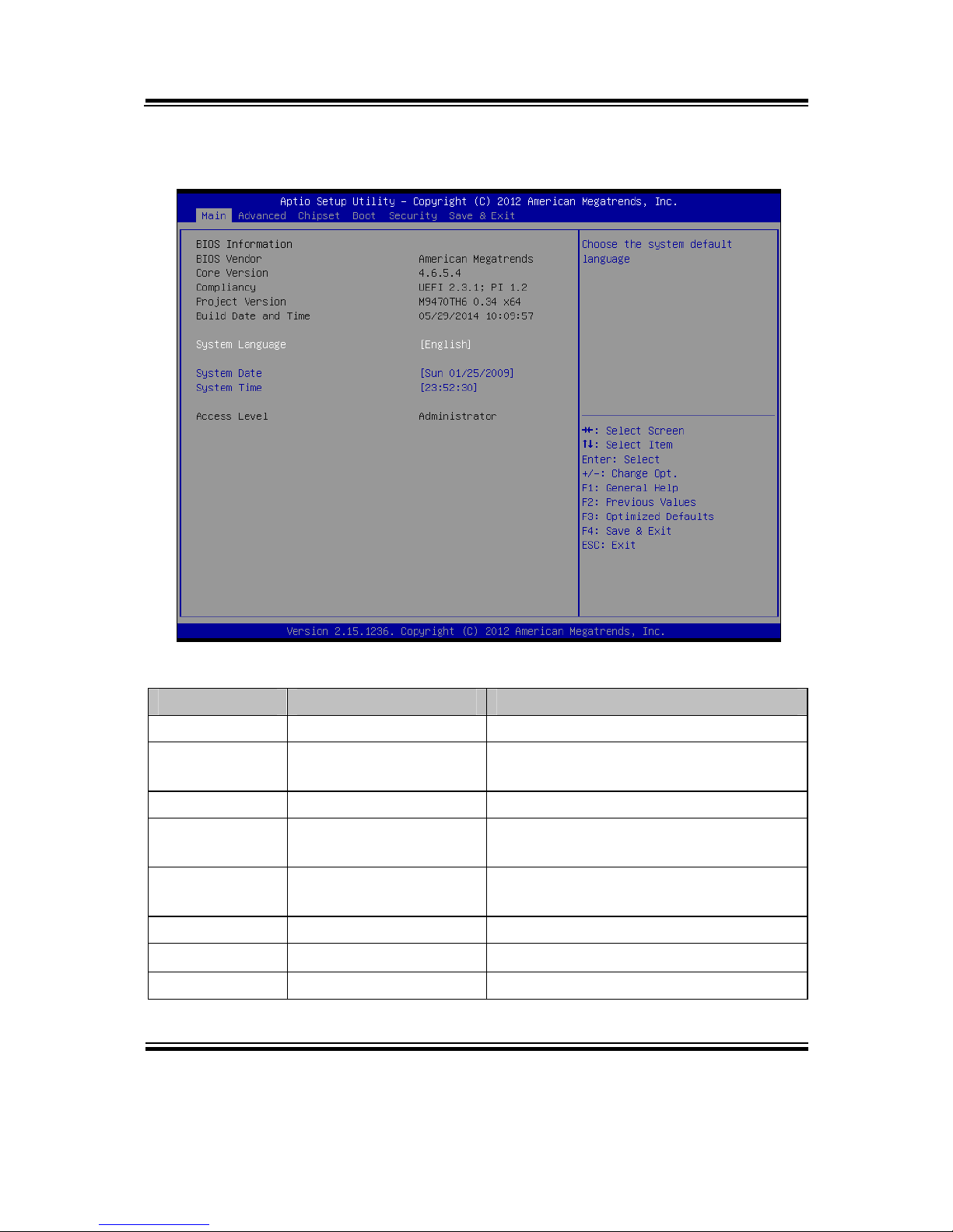
Main screen
BIOS Setting Options Description/Purpose
BIOS Vendor No changeable options Displays the BIOS vendor.
Core Version No changeable options Displays the current BIOS core
version.
Compliancy No changeable options Displays the current UEFI version.
Project
Version
No changeable options Displays the version of the BIOS
currently installed on the platform.
Build Date and
Time
No changeable options Displays the date of current BIOS
version.
System Date Month, day, year Specifies the current date.
System Time Hour, minute, second Specifies the current time.
Access Level No changeable options Displays the current user level.
Page 47
Chapter 4 BIOS Setup
BM-0947 USER′S MANUAL
Page: 4-7
4-4. ADVANCED
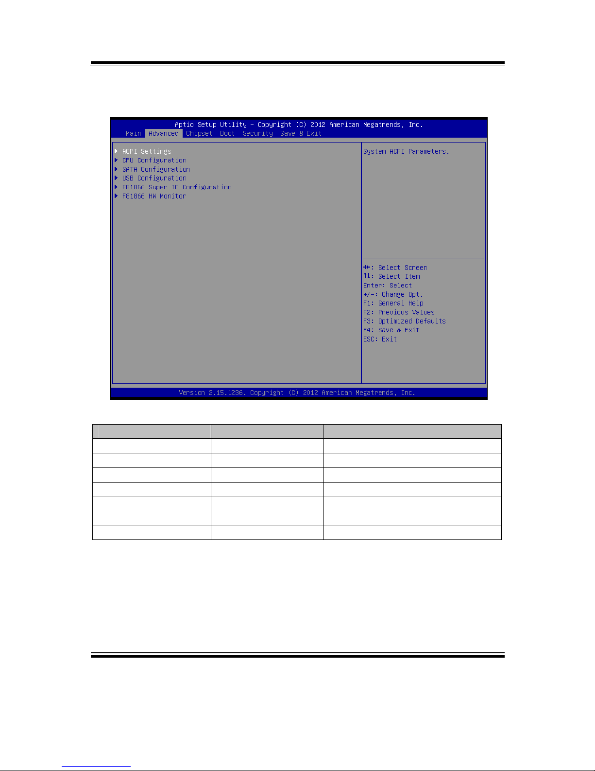
Advanced screen
BIOS Setting Options Description/Purpose
ACPI Settings Sub-Menu System ACPI Parameters.
CPU Configuration Sub-Menu CPU Configuration. Parameters.
SATA Configuration Sub-Menu SATA Configuration Parameters.
USB Configuration Sub-Menu USB Configuration Parameters.
F81866 Super IO
Configuration
Sub-Menu System Super IO Chip Parameters.
F81866 HW Monitor Sub-Menu Monitor hardware status
Page 48
Chapter 4 BIOS Setup
BM-0947 USER′S MANUAL
Page: 4-8
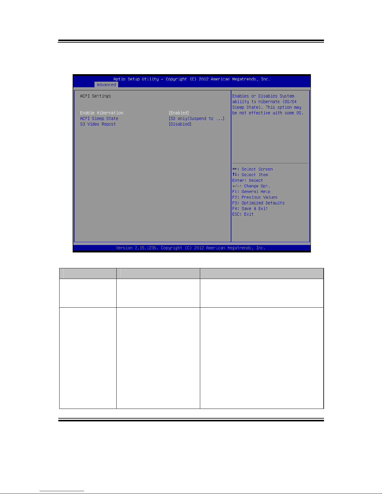
4-4-1. ACPI Settings
ACPI settings screen
BIOS Setting Options Description/Purpose
Enable
Hibernation
- Disabled
- Enabled
Enables or disables system ability to
hibernate (OS/S4 Sleep State). This
may be not effective with some OS.
ACPI Sleep
State
- Suspend Disabled
- S1 (CPU Stop Clock)
- S3 (Suspend to RAM)
- Both S1 and S3
available for OS to
choose from
Specifies the ACPI sleep state.
Suspend Disabled disables ACPI
sleep feature.
S1 mode allows the CPU enter
Stop Clock mode to stop executing
instructions.
S3 allows the platform to enter
Suspend to RAM mode.
Both S1 and S3 available for OS
to choose from allows the OS to
choose the sleep state type.
Page 49

Chapter 4 BIOS Setup
BM-0947 USER′S MANUAL
Page: 4-9
BIOS Setting Options Description/Purpose
S3 Video
Repost
- Disabled
- Enabled
Enable or Disable S3 video Repost
Page 50
Chapter 4 BIOS Setup
BM-0947 USER′S MANUAL
Page: 4-10
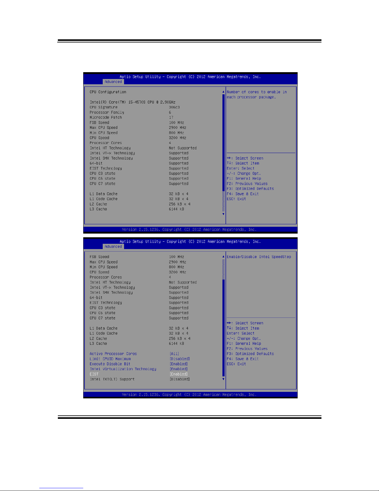
4-4-2. CPU Configuration
Page 51
Chapter 4 BIOS Setup
BM-0947 USER′S MANUAL
Page: 4-11
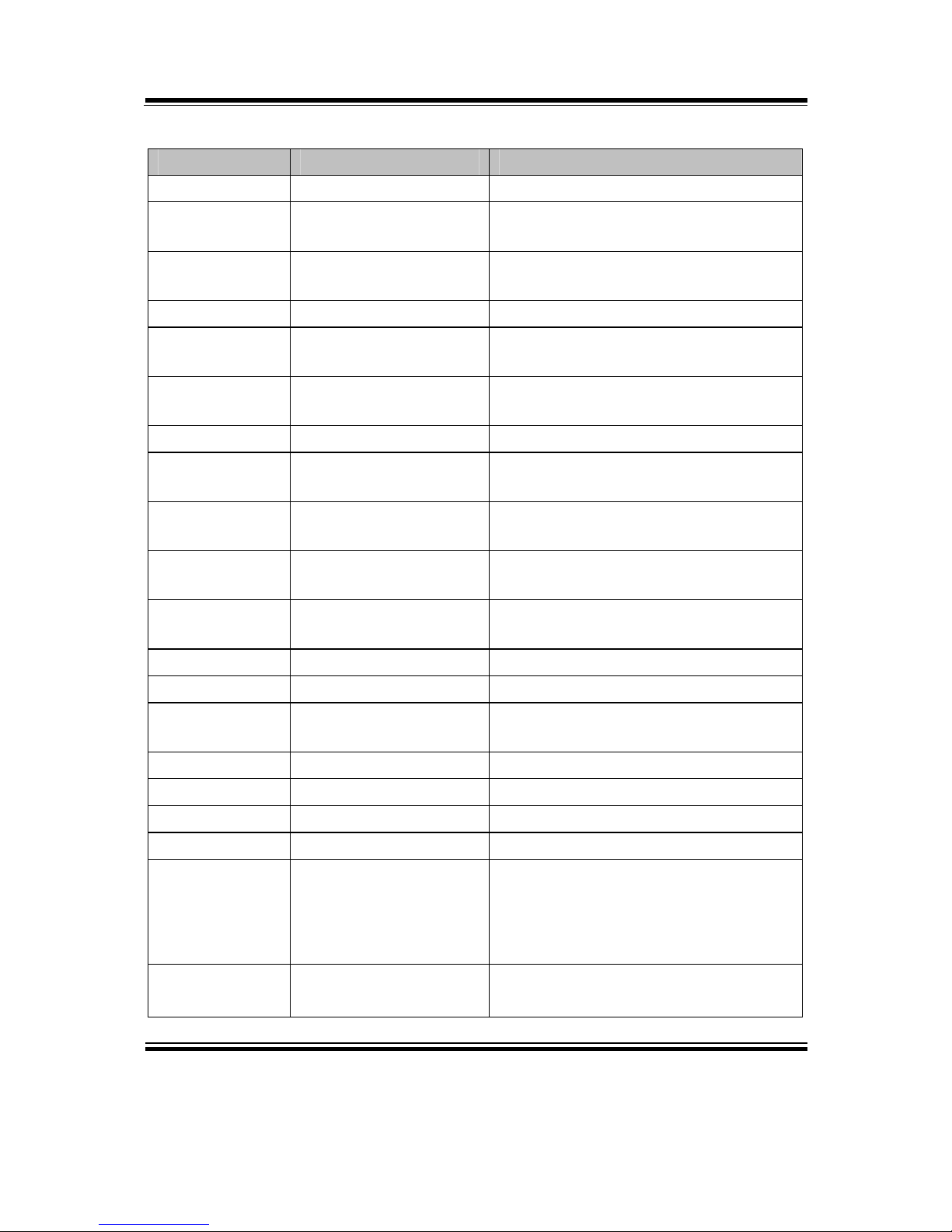
CPU configuration screen
BIOS Setting Options Description/Purpose
CPU Signature No changeable options Reports the CPU Signature
Processor
Family
No changeable options Reports the CPU Family
Microcode
Patch
No changeable options Reports the CPU Microcode Patch
Version.
FSB Speed No changeable options Display FSB Speed
Max CPU
Speed
No changeable options Reports the Max CPU Speed.
Min CPU
Speed
No changeable options Reports the Min CPU Speed
CPU Speed No changeable options Display CPU Speed
Processor
Cores
No changeable options Displays number of physical cores in
processor.
Intel HT
Technology
No changeable options Reports if Intel Hyper-Threading
Technology is supported by processor
Intel VT-x
Technology
No changeable options Reports if Intel VT-x Technology is
supported by processor.
Intel SMX
Technology
No changeable options Reports if Intel SMX Technology is
supported by processor.
64-bit No changeable options Report if 64 bit support by processor
EIST No changeable options Report if EIST support by processor
CPU C3/C6/C7
state
No changeable options Report if C3/C6/C7 support by
processor
L1 Data Cache No changeable options Displays size of L1 Data Cache
L1 Code Cache No changeable options Displays size of L1 Code Cache
L2 Cache No changeable options Displays size of L2 Cache.
L3 Cache No changeable options Displays size of L3 Cache.
Active
Processor
Cores
- All
- 1
- 2
- 3
Indicates the number of cores to
enable in processor.
Limit CPUID
Maximum
- Disabled
- Enabled
Enables for legacy operating systems
to boot processors with extended
Page 52

Chapter 4 BIOS Setup
BM-0947 USER′S MANUAL
Page: 4-12
BIOS Setting Options Description/Purpose
CPUID functions.
Execute
Disable Bit
- Disabled
- Enabled
XD can prevent certain classes of
malicious buffer overflow attacks
when combined with a supporting
OS(Windows Server 2003 SP1,
Windows XP Sp2, SuSE Linux 9.2,
Redhat Enterprise 3 Update 3.)
Intel
Virtualization
Technology
-Disabled
-Enabled
When enabled, a VMM can utilize the
additional hardware capabilities
provided by Vander pool Technology.
EIST -Disabled
-Enabled
Enable or Disable EIST
Page 53
Chapter 4 BIOS Setup
BM-0947 USER′S MANUAL
Page: 4-13
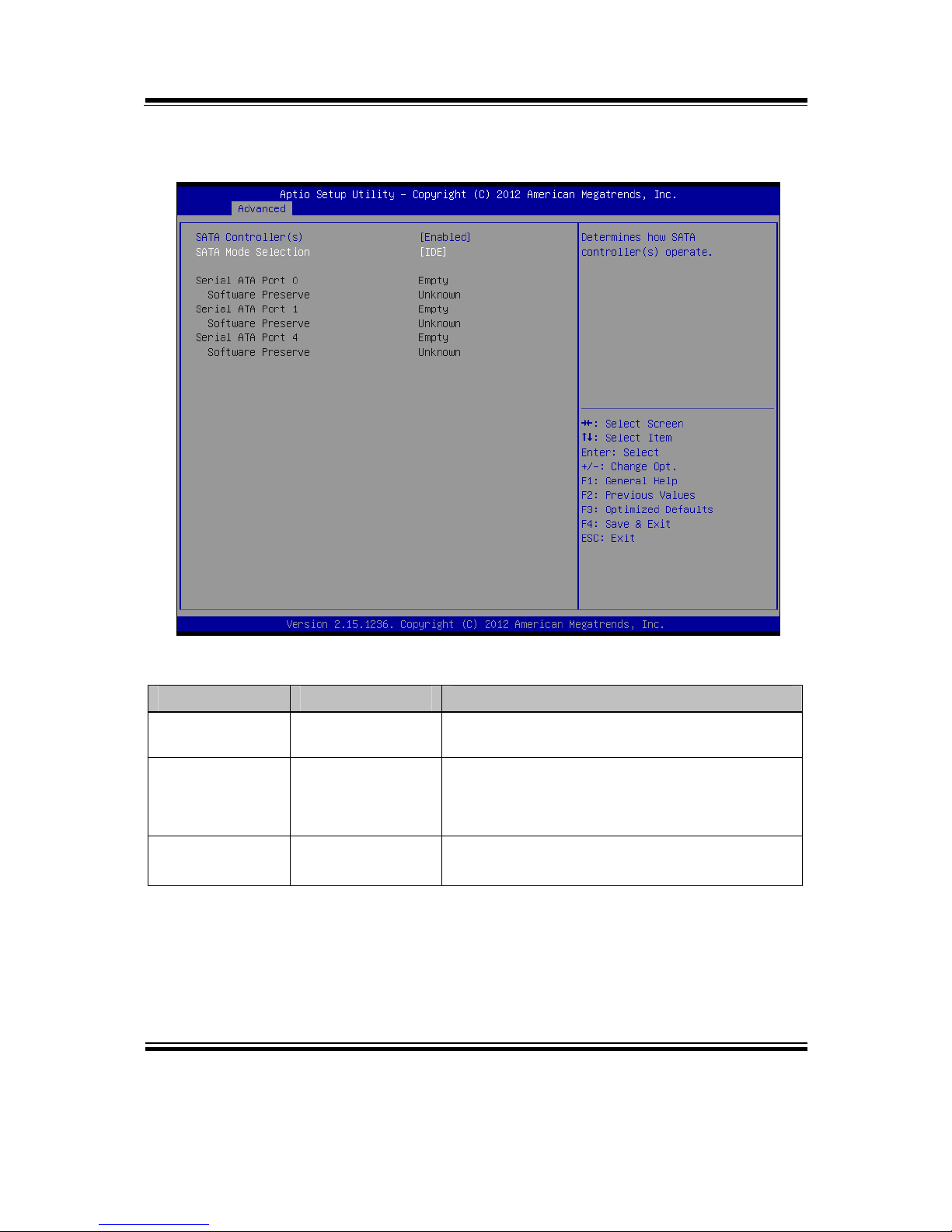
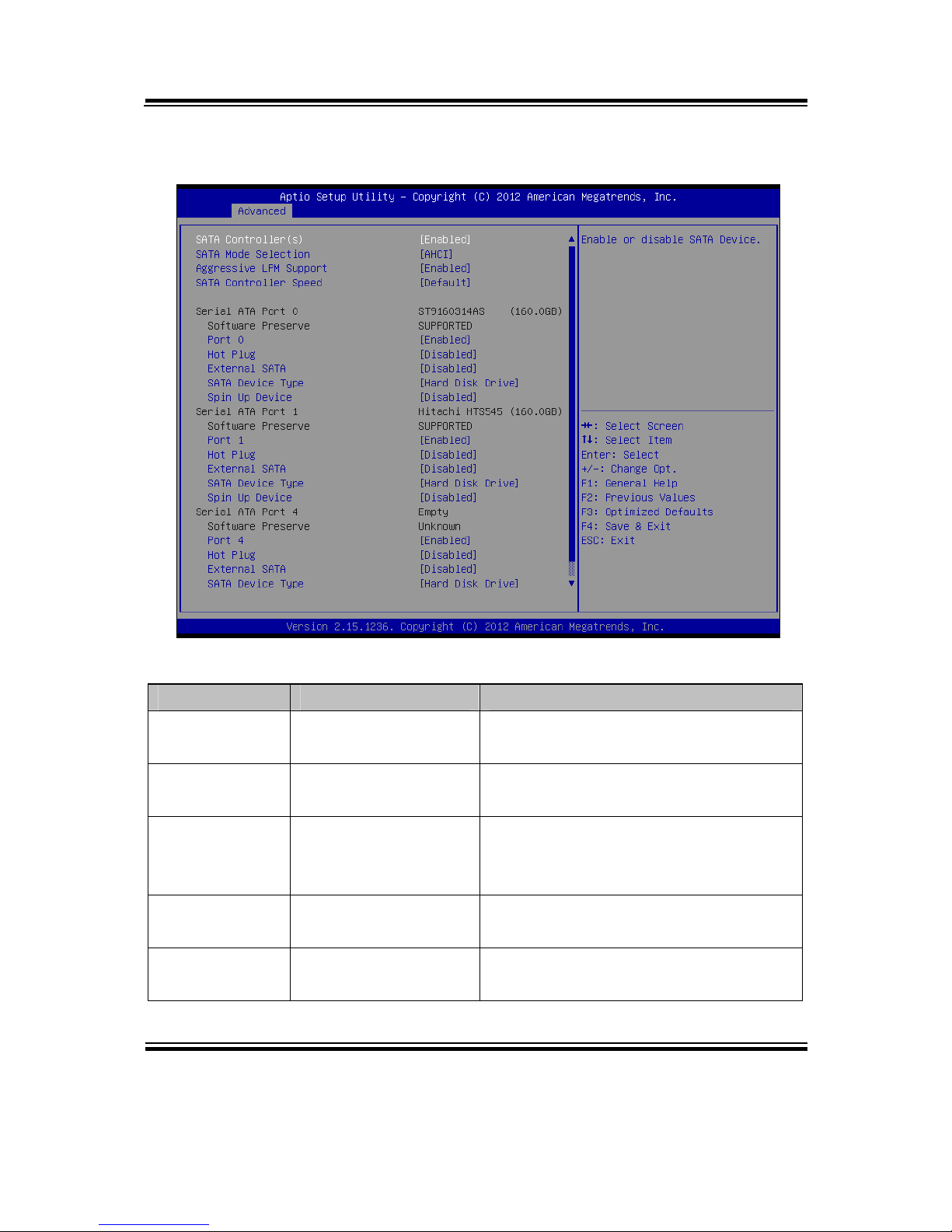
4-4-3. SATA Configuration
SATA cnfiguration screen
BIOS Setting Options Description/Purpose
SATA
Controller(s)
- Disabled
- Enabled
Enable or disable SATA Device.
SATA Mode
Selection
- IDE
- AHCI
- RAID
Configures SATA as IDE, AHCI or
RAID(Q87 only) mode.
SATA 0/1/4 [drive] Displays the drive installed on this SATA
port. Shows [Empty] if no drive is installed.
Page 54
Chapter 4 BIOS Setup
BM-0947 USER′S MANUAL
Page: 4-14
When you select SATA Mode as [AHCI] or [RAID], it shows more items as below.
AHCI/RAID screen
BIOS Setting Options Description/Purpose
SATA
Controller(s)
- Disabled
- Enabled
Enable SATA Controller
Aggressive
LPM Support
- Disabled
- Enabled
Enable PCH to aggressively enter link
power state.
SATA
Controller
Speed
- Gen1
- Gen2
- Gen3
Indicates the maximum speed the
SATA controller can support.
Port 0/1/4 - Disabled
- Enabled
Enables or disable SATA port.
Hot Plug - Disabled
- Enabled
Designates this port as Hot Pluggable.
Page 55
Chapter 4 BIOS Setup
BM-0947 USER′S MANUAL
Page: 4-15
BIOS Setting Options Description/Purpose
External SATA - Disabled
- Enabled
External SATA Support.
SATA Device
Type
- Hard Disk Driver
- Solid State Drive
Identify the SATA port is connected to
Solid State Drive or Hard Disk Drive.
Spin Up Device - Disabled
- Enabled
On an edge detect from 0 to 1, the PCH
starts a COMRESET initialization
sequence to the device.
Page 56
Chapter 4 BIOS Setup
BM-0947 USER′S MANUAL
Page: 4-16
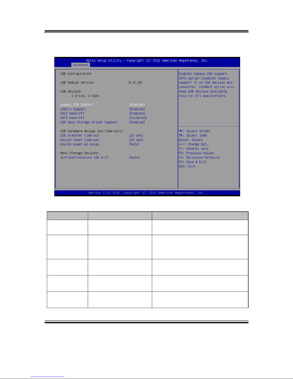
4-4-4. USB Configuration
USB configuration screen
BIOS Setting Options Description/Purpose
USB Devices No changeable options Displays number of available USB
devices.
Legacy USB
Support
- Enabled
- Disabled
- Auto
Enables support for legacy USB.
USB 3.0
Support
- Enabled
- Disabled
Enable/Disable USB3.0 (XHCI)
controller support.
XHCI Handoff
- Enabled
- Disabled
This is a workaround for OSes
without XHCI hand-off support.
EHCI Handoff
- Disabled
- Enabled
This is a workaround for OSes w/o
EHCI hand-off support.
Page 57
Chapter 4 BIOS Setup
BM-0947 USER′S MANUAL
Page: 4-17
BIOS Setting Options Description/Purpose
USB transfer
time-out
1/5/10/20 sec The time-out value for Control, Bulk,
and Interrupt transfers.
Device reset
time-out
10/20/30/40 sec USB mass storage device Start Unit
command time-out.
Device powerup delay
- Auto
- Manual
Maximum time the device will take
before it properly reports itself to the
Host Controller. 'Auto' uses default
value: for a Root port it is 100 ms, for
a Hub port the delay is taken from
Hub descriptor.
Page 58
Chapter 4 BIOS Setup
BM-0947 USER′S MANUAL
Page: 4-18
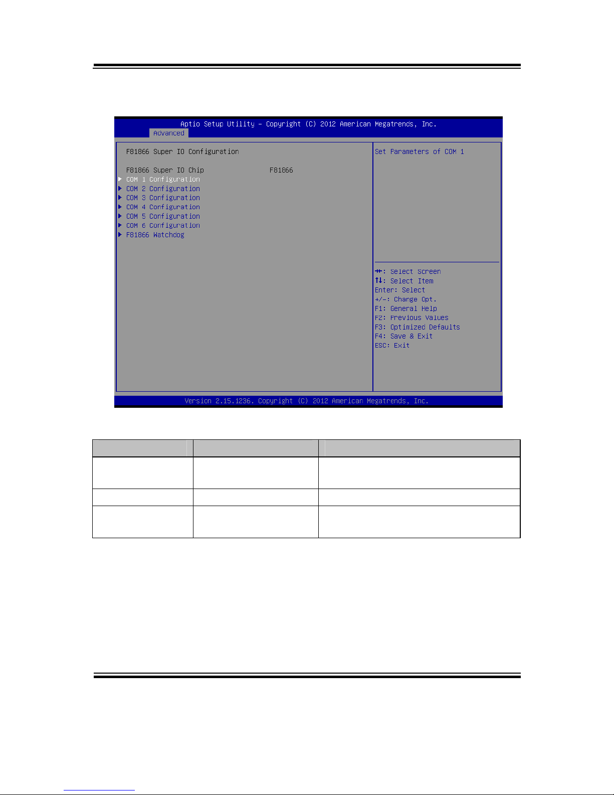
4-4-5. F81866 Super IO Configuration
F81866 Super IO Configuration screen
BIOS Setting Options Description/Purpose
F81866 Super IO
Chip
No changeable options Displays the super IO chip model and
its manufacturer.
COM 1/2/3/4/5/6 Sub-menu Set Parameters for COM 1/2/3/4/5/6
F81866
Watchdog
Sub-menu Set watchdog time
Page 59
Chapter 4 BIOS Setup
BM-0947 USER′S MANUAL
Page: 4-19
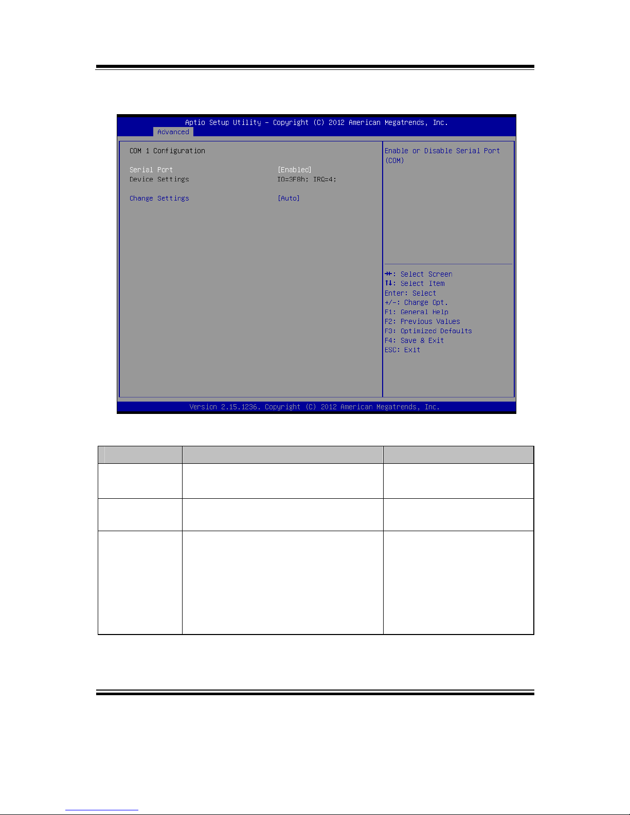
4-4-5-1. COM 1/2/3/4/5/6 Configuration
COM 1/2/3/4/5/6 Configuration screen
BIOS Setting Options Description/Purpose
Serial Port - Disabled
- Enabled
Enable/Disable COM 1.
Device
Settings
No changeable options Reports the current COM 1
setting.
Change
Settings
- Auto
- IO=3F8h; IRQ=4
- IO=3F8h; IRQ=3,4,5,6,7,10,11,12
- IO=2F8h; IRQ=3,4,5,6,7,10,11,12
- IO=3E8h; IRQ=3,4,5,6,7,10,11,12
- IO=2E8h; IRQ=3,4,5,6,7,10,11,12
Specifies the base I/O
address and interrupt
request for the serial port 0
if enabled.
Page 60
Chapter 4 BIOS Setup
BM-0947 USER′S MANUAL
Page: 4-20
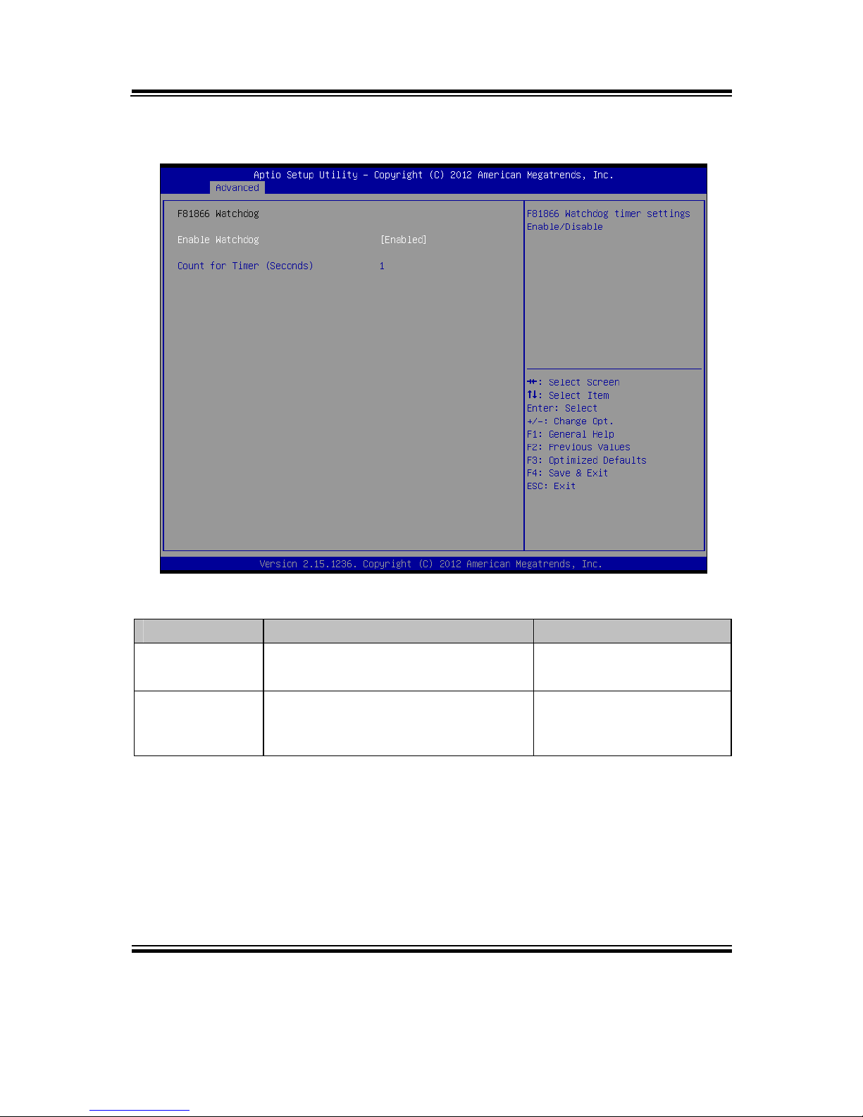
4-4-5-2. F81866 Watchdog
F81866 Watchdog screen
BIOS Setting Options Description/Purpose
Enable
watchdog
- Disabled
- Enabled
Enable/Disable COM 1.
Count for
Timer
(Seconds)
Timer value The number of second
count for timer (1-255
seconds)
Page 61
Chapter 4 BIOS Setup
BM-0947 USER′S MANUAL
Page: 4-21
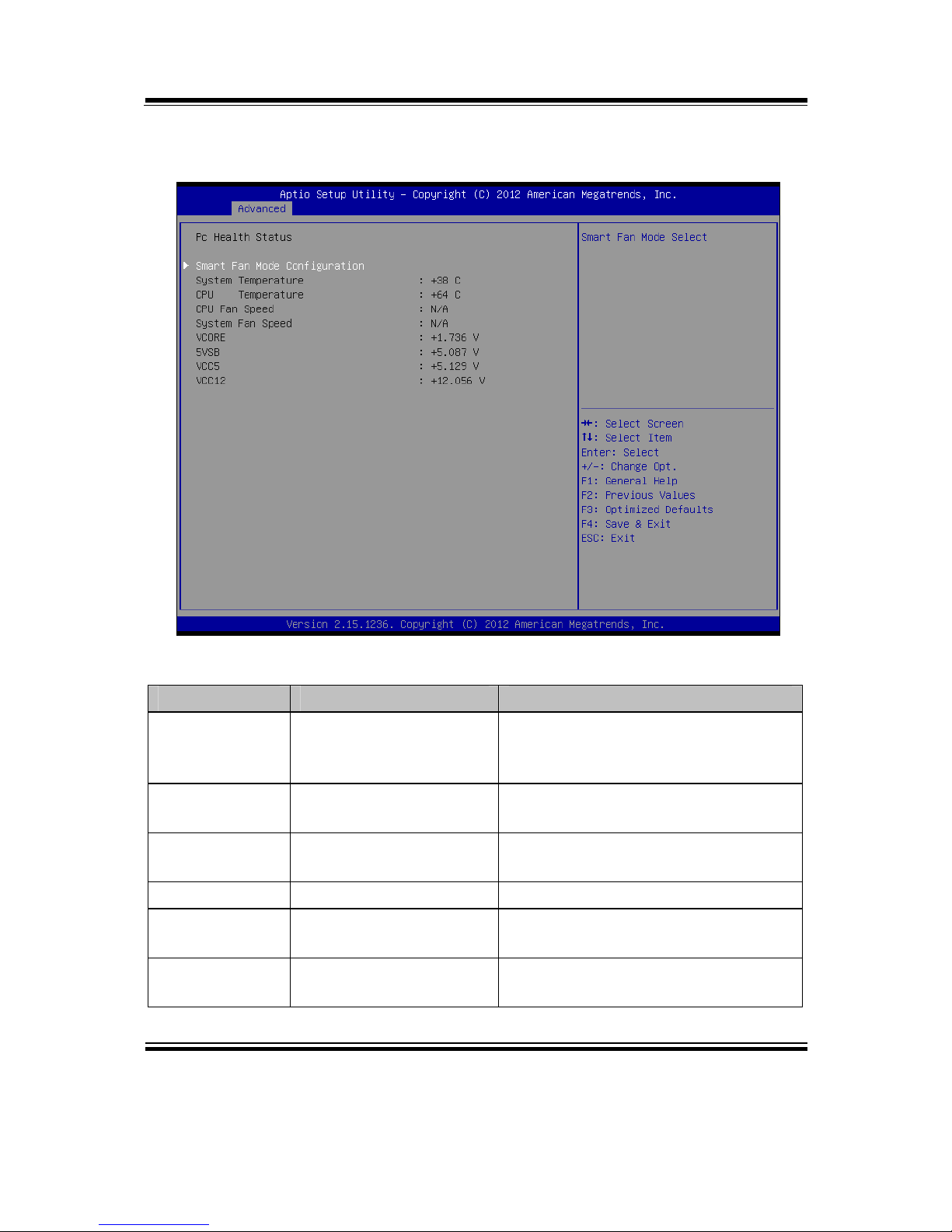
4-4-6. F81866 Hardware Monitor
F81866 Hardware Monitor screen
BIOS Setting Options Description/Purpose
Smart Fan
Mode
Configuration
Sub-menu Smart Fan Mode select.
System
Temperature
No changeable options Displays temperature in the remote
thermal sensor zone.
CPU
Temperature
No changeable options Displays processor's temperature.
CPU Fan Speed No changeable options Displays fan speed of the CPU fan.
System Fan
Speed
No changeable options Displays fan speed of the system fan
VCORE No changeable options Displays voltage level of the +Vcore
in supply.
Page 62
Chapter 4 BIOS Setup
BM-0947 USER′S MANUAL
Page: 4-22
BIOS Setting Options Description/Purpose
5VSB No changeable options Displays voltage level of the +5V in
supply.
VCC5 No changeable options Displays voltage level of the +5V in
supply.
VCC12 No changeable options Displays voltage level of the +12V
in supply.
Page 63
Chapter 4 BIOS Setup
BM-0947 USER′S MANUAL
Page: 4-23
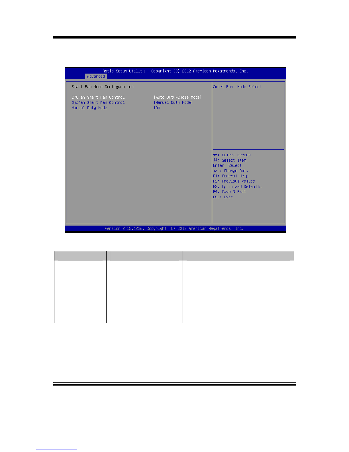
4-4-6-1. Smart Fan Mode Configuration
Smart Fan Mode Configuration screen
BIOS Setting Options Description/Purpose
CPUFan/
SysFan Samrt
Fan Control
- Manual Duty Mode
- Auto Duty-Cycle Mode
Smart Fan Mode select.
Manual Duty
Mode
Duty value Set duty cycle(PWM fan type) 1-100
Auto DutyCycle Mode
No selection Fan speed up/down is determined by
temperature
Page 64
Chapter 4 BIOS Setup
BM-0947 USER′S MANUAL
Page: 4-24
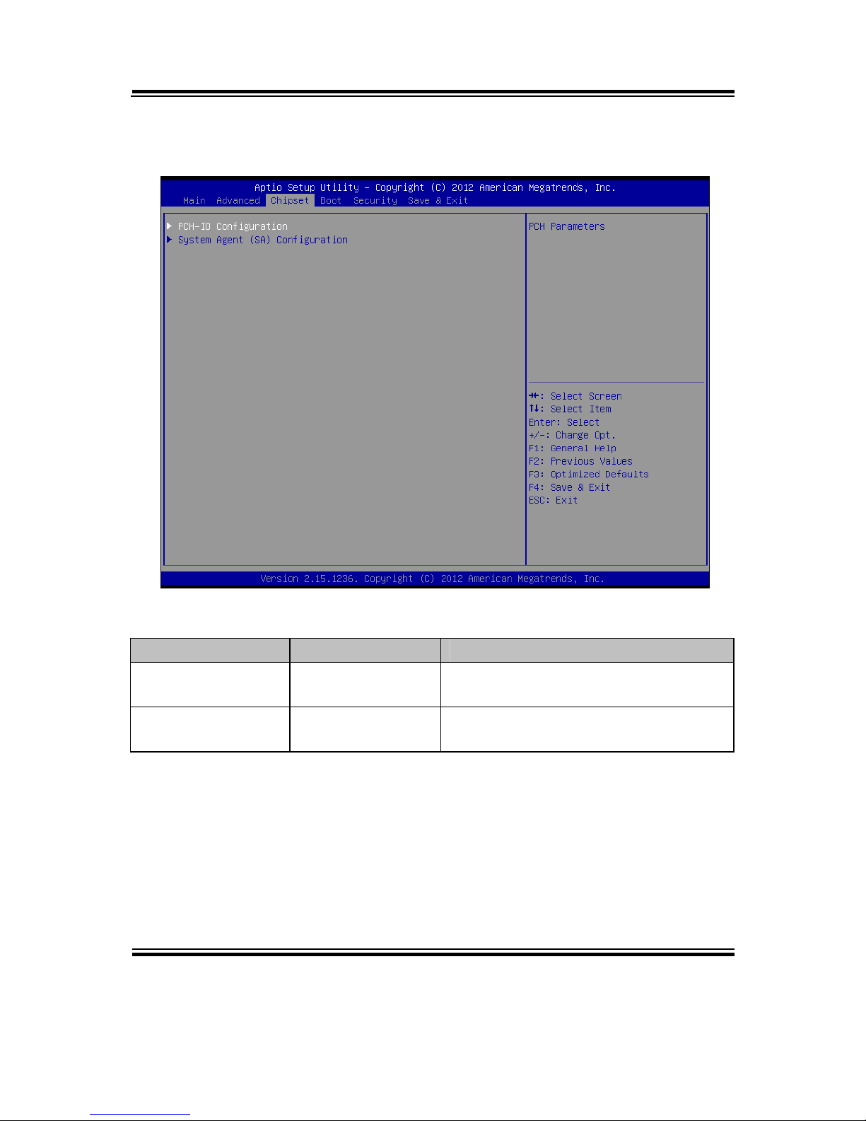
4-5. CHIPSET
Chipset screen
BIOS Setting Options Description/Purpose
PCH-IO
Configuration
Sub-menu Sets Parameter for Panther Point
(South Bridge) configuration.
System Agent (SA)
Configuration
Sub-menu Sets Parameter for Ivy Bridge (North
Bridge) configuration.
Page 65
Chapter 4 BIOS Setup
BM-0947 USER′S MANUAL
Page: 4-25
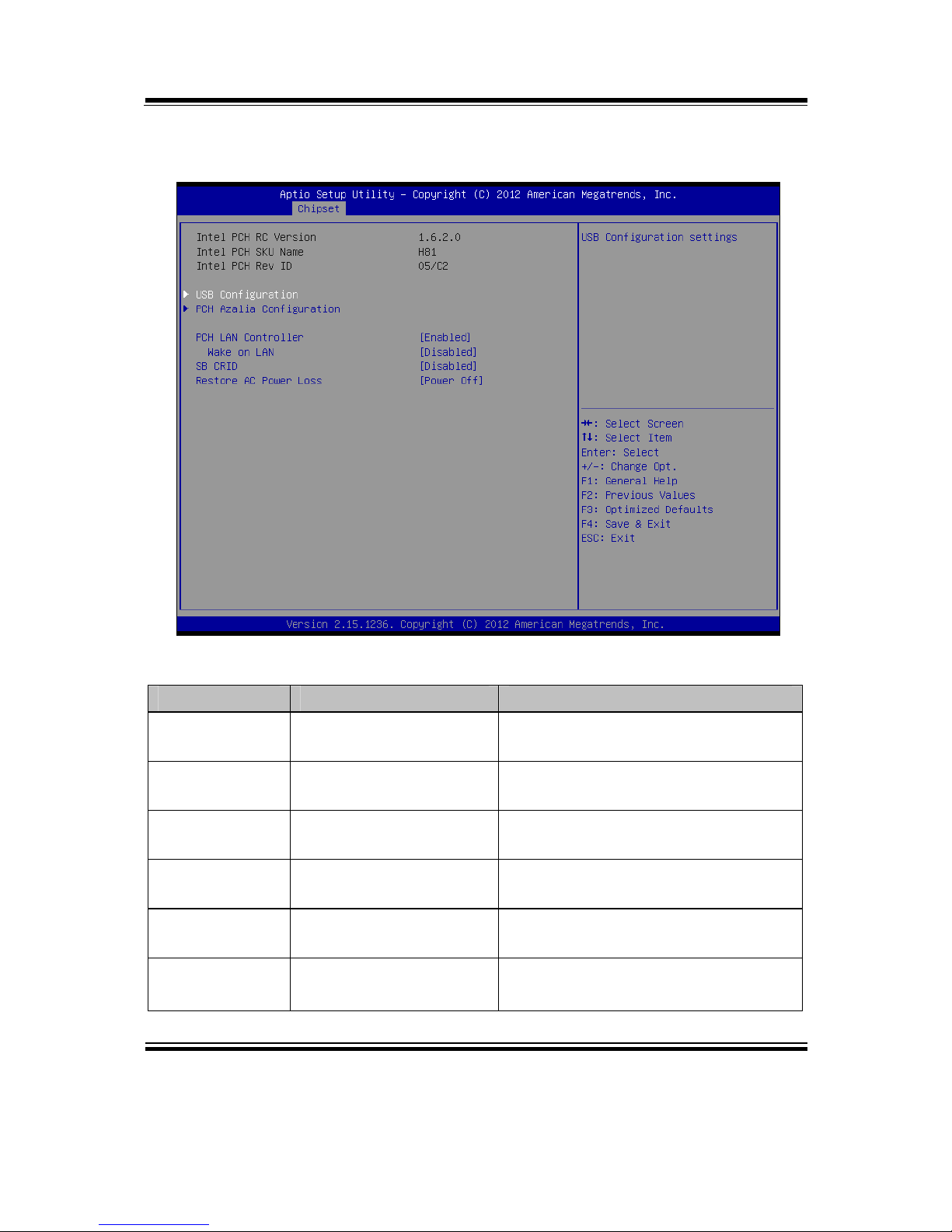
4-5-1. PCH IO Configuration
PCH IO Configuration screen
BIOS Setting Options Description/Purpose
Intel PCH RC
Version
No changeable options Displays the PCH source code
module version
Intel PCH SKU
Name
No changeable options Displays PCH product SKU name.
Intel PCH Rev
ID
No changeable options Displays onboard PCH chip revision.
USB
Configuration
Sub-menu USB Configuration setting
PCH Azalia
Configuration
Sub-menu PCH Azalia Configuration settings.
PCH LAN
Controller
- Disabled
- Enabled
Enable or disable onboard NIC
Page 66

Chapter 4 BIOS Setup
BM-0947 USER′S MANUAL
Page: 4-26
BIOS Setting Options Description/Purpose
Wake on LAN - Disabled
- Enabled
Enable or disable integrated LAN to
wake the system. (The Wake On
LAN cannot be disabled if ME is on
at Sx state.)
SB CRID - Disabled
- Enabled
Enable or disable SB CRID
workaround
Restore AC
Power Loss
- Power off
- Power on
Select AC power state when power is
re-applied after a power failure.
Page 67
Chapter 4 BIOS Setup
BM-0947 USER′S MANUAL
Page: 4-27
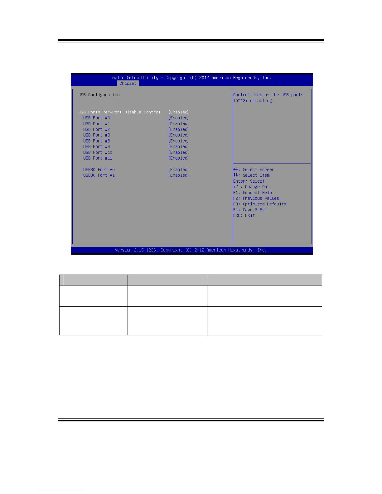
4-5-1-1. USB Configuration
USB Configuration screen
BIOS Setting Options Description/Purpose
USB Ports Per-Port
Disable Control
- Enabled
- Disabled
Main control to enable or disable
USB ports.
USB Port
#0/1/2/3/8/9/10/11
USB30 Port #0/1
- Enabled
- Disabled
Enable or disable each USB ports.
Page 68
Chapter 4 BIOS Setup
BM-0947 USER′S MANUAL
Page: 4-28
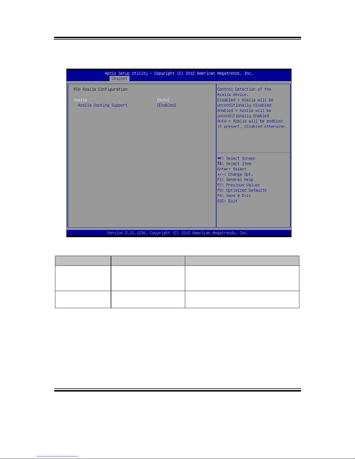
4-5-1-2. PCH Azalia Configuration
PCH Azalia Configuration screen
BIOS Setting Options Description/Purpose
Azalia - Enabled
- Disabled
- Auto
Enable or disable internal HDMI
codec for Azalia.
Azalia Docking
Support
- Enabled
- Disabled
Enable or disable Azalia Docking
Support of Audio Controller
Page 69
Chapter 4 BIOS Setup
BM-0947 USER′S MANUAL
Page: 4-29
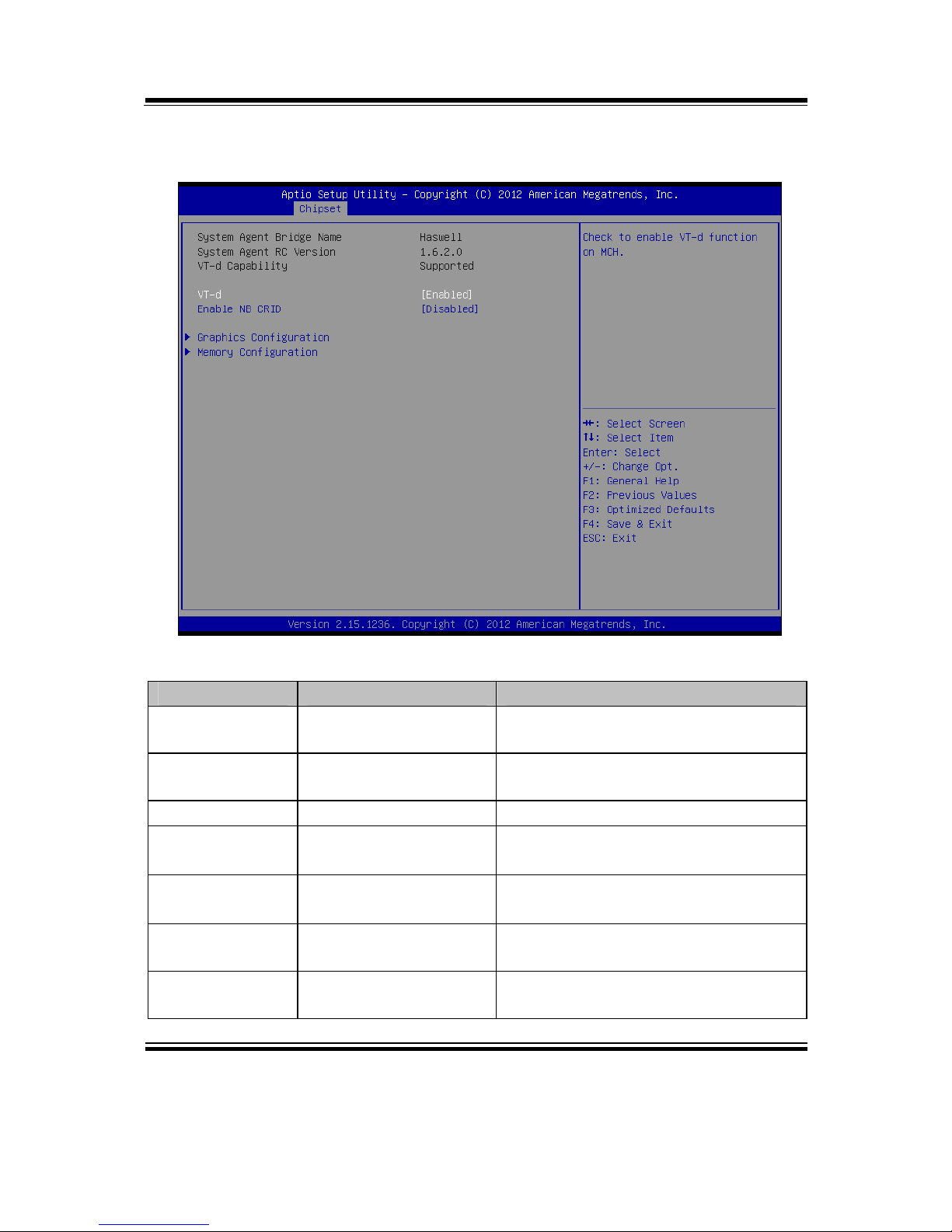
4-5-2. System Agent (SA) Configuration
System Agent (SA) Configuration screen
BIOS Setting Options Description/Purpose
System Agent
Bridge Name
No changeable options Displays the system bridge name..
System Agent
RC version
No changeable options Displays the IVB source code module
version
VT-d Capability No changeable options Report if VT-d support by processor
VT-d - Enabled
- Disabled
Enable or disable VT-d
Enable NB
CRID
- Enabled
- Disabled
Enable or disable NB CRID
workaround.
Graphics
Configuration
Sub-menu Configure Graphic Settings.
Memory
Configuration
Sub-menu Memory Configuration Parameters
Page 70
Chapter 4 BIOS Setup
BM-0947 USER′S MANUAL
Page: 4-30
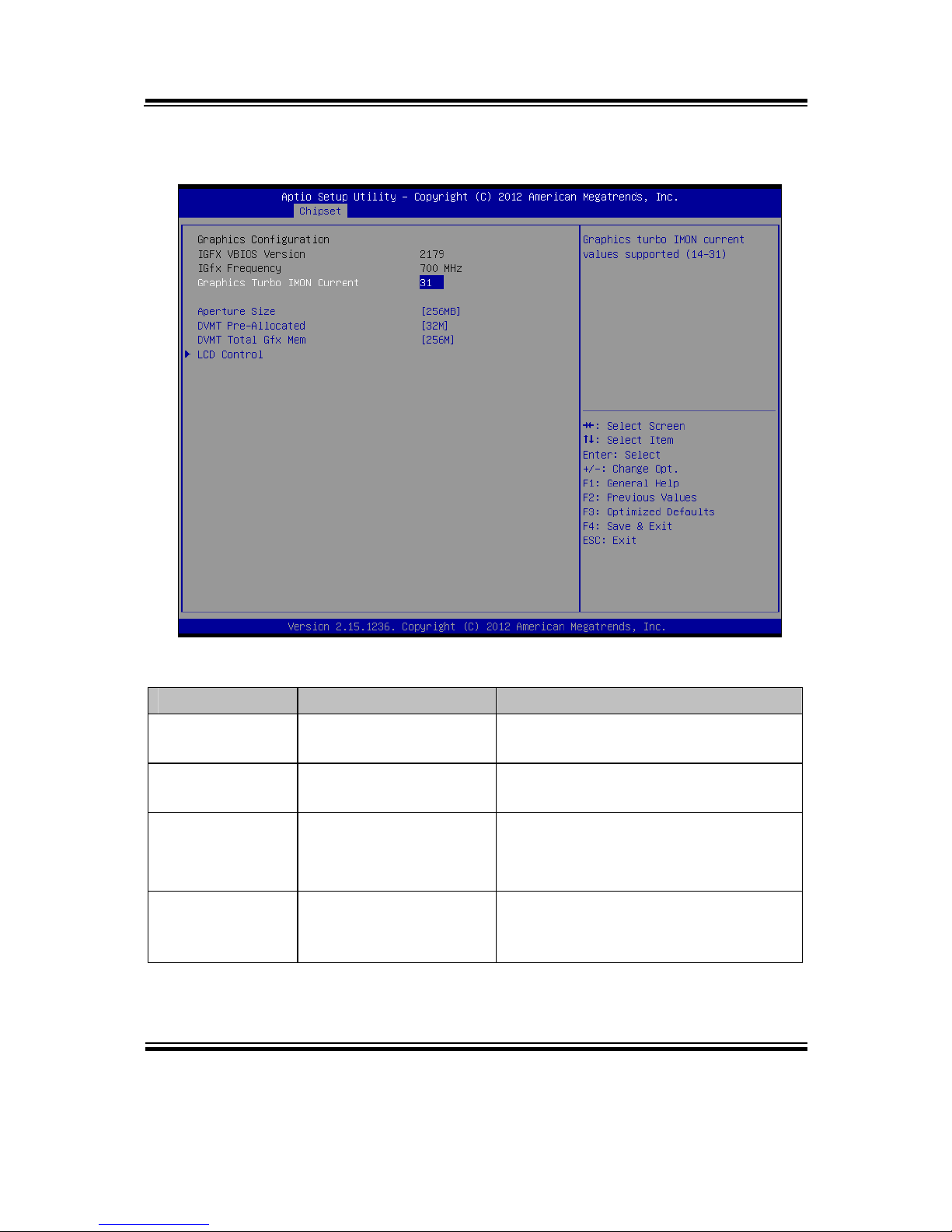
4-5-2-1. Graphics Configuration
Graphics Configuration screen
BIOS Setting Options Description/Purpose
IGFX VBIOS
Version
No changeable options Displays the VBIOS version of
integrated graphic controller.
IGfx Frequency No changeable options Displays the frequency integrated
graphic controller.
Aperture Size - 128MB
- 256MB
- 512MB
Select the Aperture Size
DVMT PreAllocated
- 32M ~ 1024M Select DVMT 5.0 Pre-Allocated
(Fixed) Graphics Memory size used
by the Internal Graphics Device.
Page 71
Chapter 4 BIOS Setup
BM-0947 USER′S MANUAL
Page: 4-31
BIOS Setting Options Description/Purpose
DVMT Total
Gfx Mem
- 128M
- 256M
- MAX
Intel Dynamic Video Memory
Technology allows additional
memory to be allocated for graphics
usage based on application need.
Once the application is closed, the
memory that was allocated for
graphics usage is then released and
made available for system use.
LCD Control Sub-menu Display devices active selection
Page 72
Chapter 4 BIOS Setup
BM-0947 USER′S MANUAL
Page: 4-32
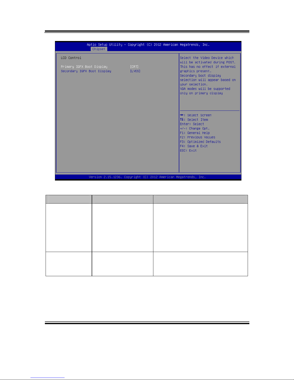
Graphics Configuration - LCD Control screen
BIOS Setting Options Description/Purpose
Primary IGFX
Boot Display
- CRT
- LVDS
"Select the Video Device which will
be activated during POST. This has
no effect if external graphics present.
Secondary boot display selection will
appear based on your selection. VGA
modes will be supported only on
primary display"
Secondary IGFX
Boot Display
- Disabled
- CRT
- LVDS
Select Secondary Display Device
Page 73
Chapter 4 BIOS Setup
BM-0947 USER′S MANUAL
Page: 4-33
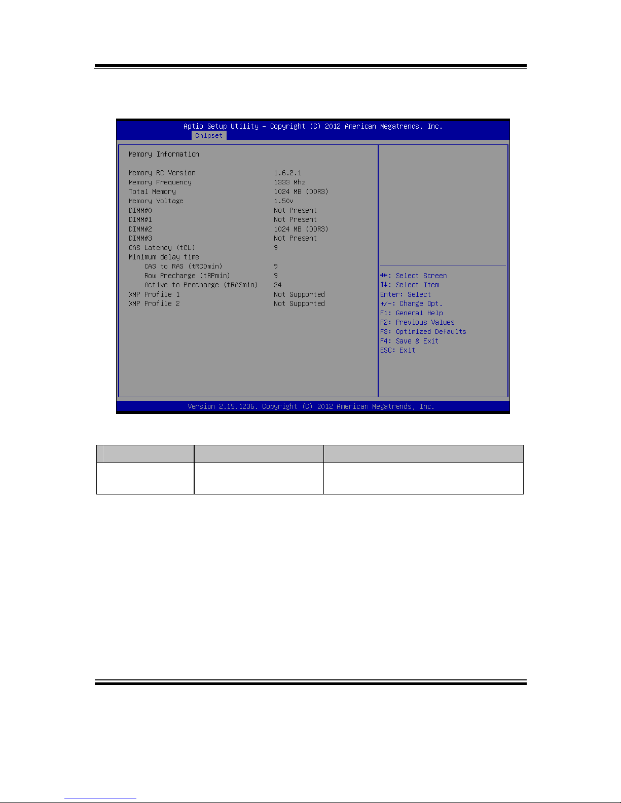
4-5-2-2. Memory Configuration
Memory Configuration screen
BIOS Setting Options Description/Purpose
Memory
Information
No changeable option . Displays the detail DRAM
information on platform.
Page 74
Chapter 4 BIOS Setup
BM-0947 USER′S MANUAL
Page: 4-34
4-6. BOOT
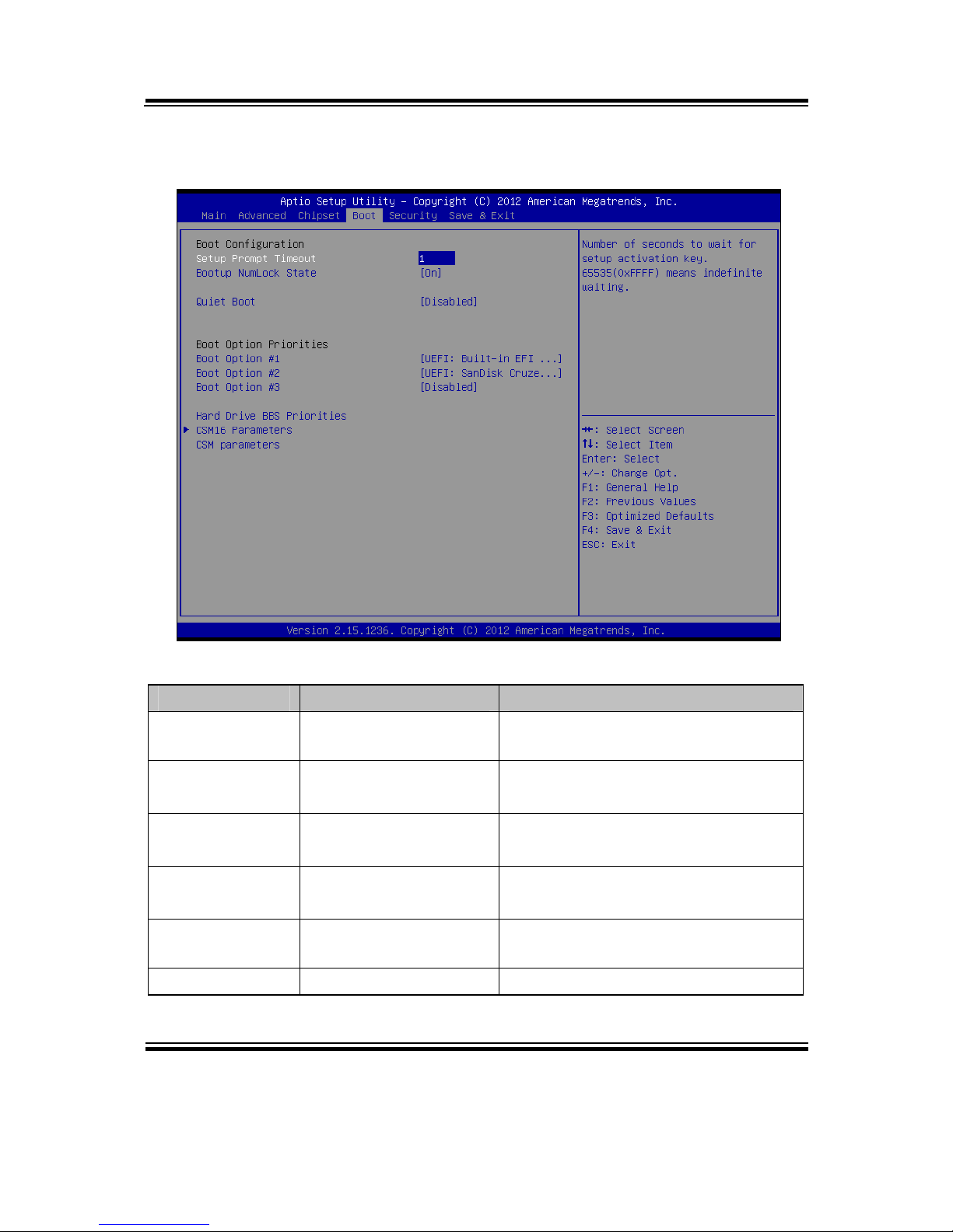
Boot screen
BIOS Setting Options Description/Purpose
Setup Prompt
Timeout
Numeric Number of seconds to wait for setup
activation key.
Bootup
NumLock Status
- On
- Off
Specifies the power-on state of the
NumLock Key.
Quiet Boot - Disabled
- Enabled
Enable/Disable Quiet Boot Options
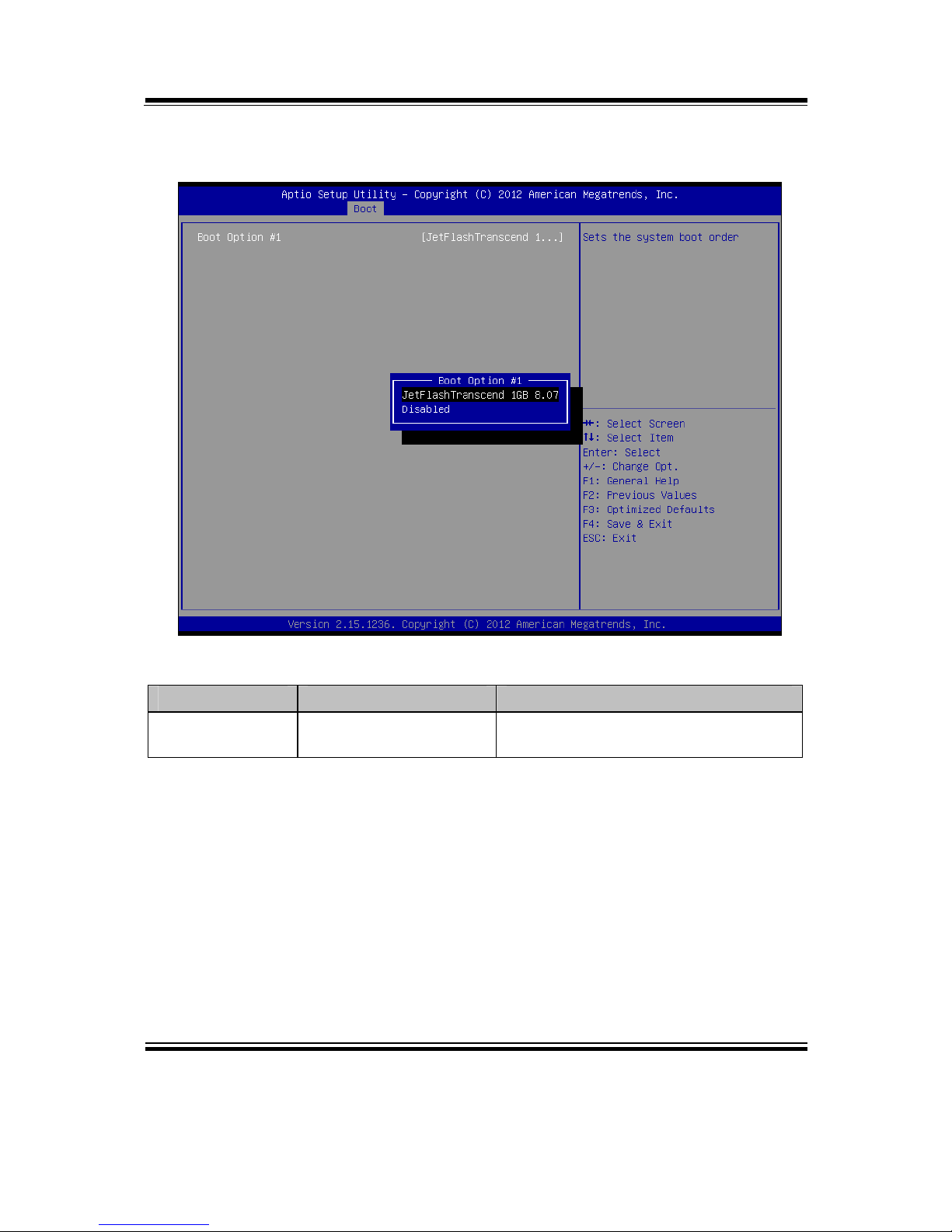
Boot Option
#1~#3
- [Drive(s)]
- Disabled
Allows setting boot option listed in
Hard Drive BBS Priorities.
CSM16
Parameters
Sub-menu CSM features selection
CSM parameters Sub-menu CSM features selection
Page 75
Chapter 4 BIOS Setup
BM-0947 USER′S MANUAL
Page: 4-35
4-6-1. Hard Drive BBS Priorities
Hard Drive BBS Priorities screen
BIOS Setting Options Description/Purpose
Boot Option #1 #3
- [Drive(s)]
- Disabled
Allows setting the boot order of
available drive(s).
Page 76
Chapter 4 BIOS Setup
BM-0947 USER′S MANUAL
Page: 4-36
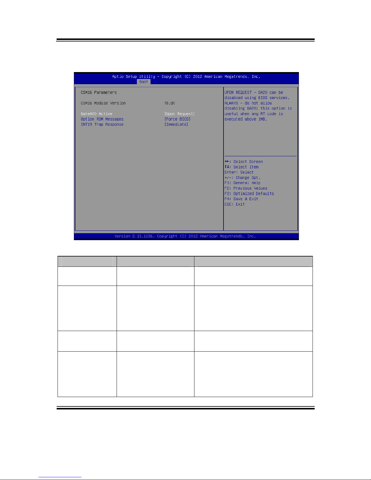
4-6-2. CSM16 Parameters
CSM16 parameters screen
BIOS Setting Options Description/Purpose
CSM16 Module
Version
78.d0 CSM version information
GateA20 Active - Upon Request
- Always
Specifies Gate-A20 logic gate status.
At boot time, Gate-A20 is enabled
when counting and testing of all the
system's memory and disabled before
transferring control to OS.
Option ROM
Messages
- Force BIOS
- Keep Current
Allows the POST screen to display
Option ROM messages.
INT19 Trap
Response
- Immediate
- Postponed
When enabled it allows host adapters
ROM BIOS to capture Interrupt 19
during the boot process and
eventually boot from disk(s)
connected to those adapters.
Page 77
Chapter 4 BIOS Setup
BM-0947 USER′S MANUAL
Page: 4-37
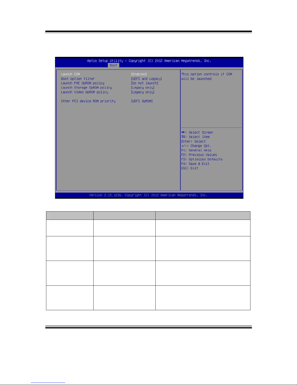
4-6-3. CSM Parameters
CSM parameters screen
BIOS Setting Options Description/Purpose
Launch CSM - Disabled
- Enabled
This option controls if CSM will be
launched
Boot option
filter
- UEFI and Legacy
- Legacy only
- UEFI only
Allows the system run the boot
option rom type.
Launch PXE
OpROM policy
- Do not launch
- UEFI only
- Legacy only
Controls the execution of UEFI and
Legacy PXE OpROM
Launch Storage
OpROM policy
- Do not launch
- UEFI only
- Legacy only
Controls the execution of UEFI and
Legacy Storage OpROM
Page 78

Chapter 4 BIOS Setup
BM-0947 USER′S MANUAL
Page: 4-38
BIOS Setting Options Description/Purpose
Launch Video
OpROM policy
- Do not launch
- UEFI only
- Legacy only
- Legacy first
- UEFI first
Controls the execution of UEFI and
Legacy Video OpROM
Other PCI
device ROM
priority
- UEFI OpROM
- Legacy OpROM
For PCI devices other than Network,
Mass storage or Video defines which
OpROM to launch
Page 79
Chapter 4 BIOS Setup
BM-0947 USER′S MANUAL
Page: 4-39
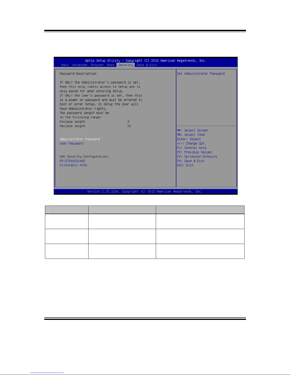
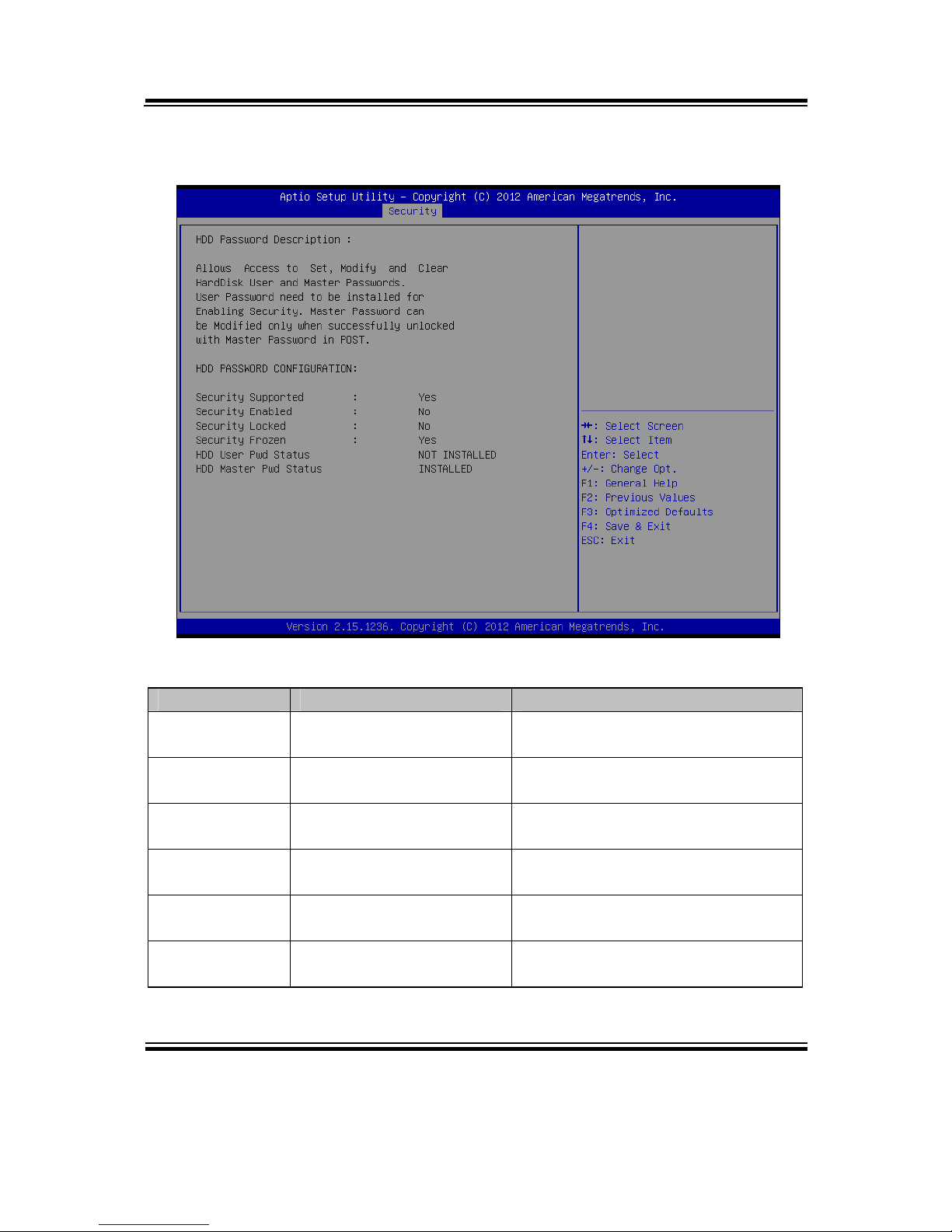
4-7. SECURITY
Security screen
BIOS Setting Options Description/Purpose
Administrator
Password
Password can be 3-20
alphanumeric characters.
Specifies the administrator
password.
User Password Password can be 3-20
alphanumeric characters.
Specifies the user password.
HDD Security
Configuration:
Sub-menu Set HDD password.
Page 80
Chapter 4 BIOS Setup
BM-0947 USER′S MANUAL
Page: 4-40
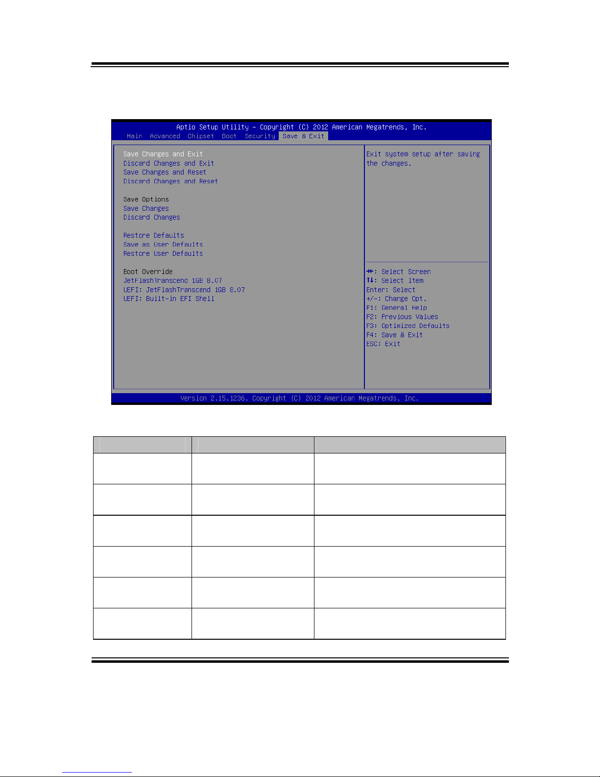
4-7-1. HDD Security Configuration
HDD Security Configuration screen
BIOS Setting Options Description/Purpose
Security
Supported
No changeable options Reports if there is security feature
available.
Security
Enabled
No changeable options Reports if there is security feature
enabled.
Security
Locked
No changeable options Reports if there is security feature
locked.
Security Frozen No changeable options Reports if there is security feature
frozen.
HDD User Pwd
Status
No changeable options Reports if there is HDD User
Password installed.
HDD Master
Pwd Status
No changeable options Reports if there is HDD Master
Password installed.
Page 81

Chapter 4 BIOS Setup
BM-0947 USER′S MANUAL
Page: 4-41
BIOS Setting Options Description/Purpose
Set User
Password
Password can be up to 32
alphanumeric characters.
Specifies the user password. (Need
TPM module)
Set Master
Password
Password can be up to 32
alphanumeric characters.
Specifies the master password.
Page 82
Chapter 4 BIOS Setup
BM-0947 USER′S MANUAL
Page: 4-42
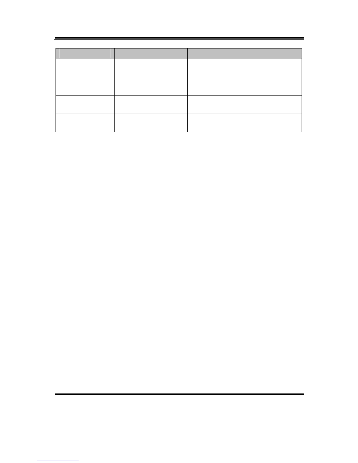
4-8. SAVE & EXIT
Save & Exit screen
BIOS Setting Options Description/Purpose
Save Changes
and Exit
No changeable options Exits and saves the changes in
NVRAM.
Discard Changes
and Exit
No changeable options Exits without saving any changes
made in BIOS settings.
Save Changes
and Reset
No changeable options Reset the system after saving the
changes
Discard Changes
and Reset
No changeable options Reset system without saving any
changes
Save Changes No changeable options Saves the changes done in BIOS
settings so far.
Discard Changes No changeable options Discards the changes done in BIOS
settings so far.
Page 83
Chapter 4 BIOS Setup
BM-0947 USER′S MANUAL
Page: 4-43
BIOS Setting Options Description/Purpose
Restore Defaults No changeable options Loads the optimized defaults for
BIOS settings.
Save as User
Defaults
No changeable options Save the changes done so far as User
Defaults
Restore User
Defaults
No changeable options Restore the User Defaults to all the
setup options
Boot Override - [Drive(s)] Forces to boot from selected
[drive(s)].
Page 84

Page: A-1
EXPANSION
BUS
This appendix indicates the pin assignments of expansion bus.
Sections included:
PCIe Bus
APPENDIX
A
Page 85
Appendix A Expansion Bus
BM-0947 USER′S MANUAL
Page: A-2
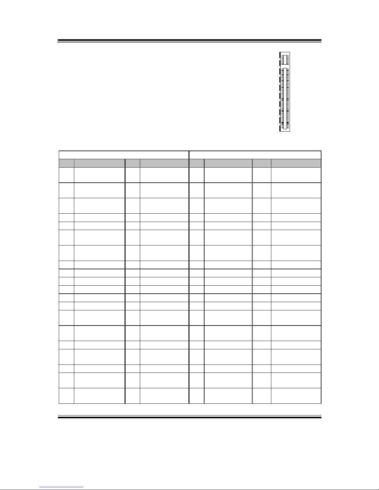
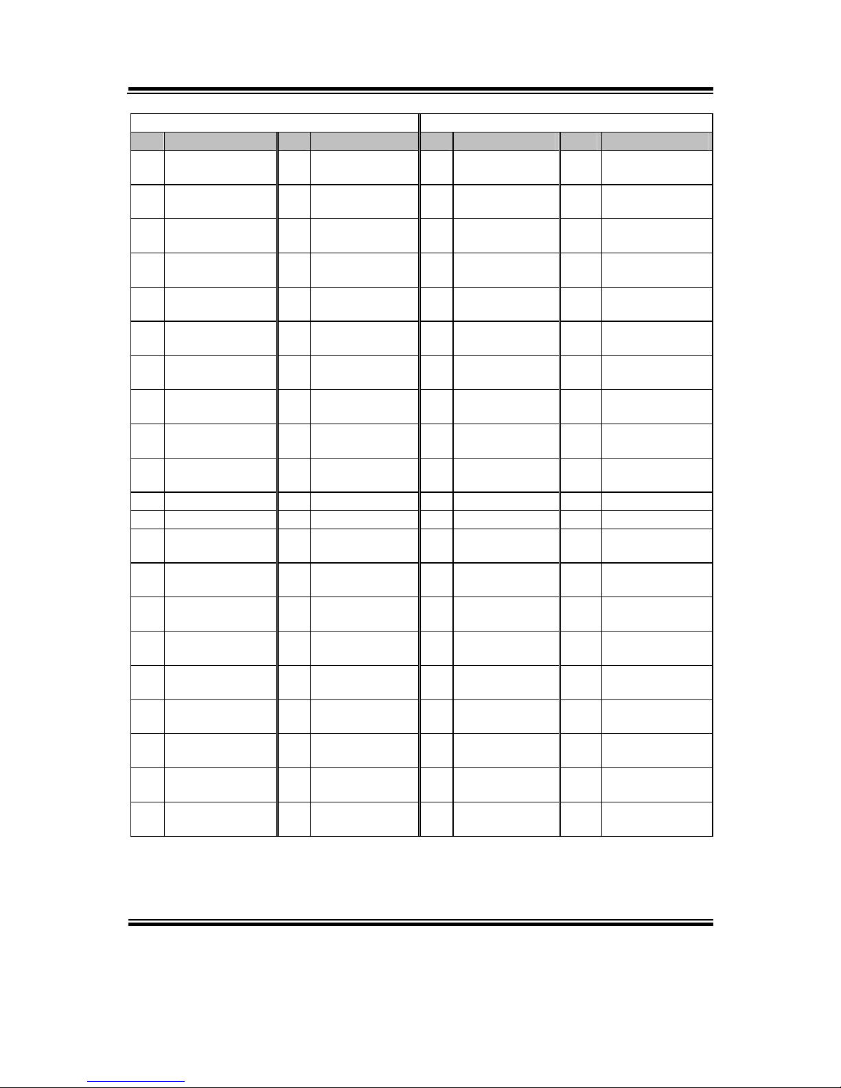
PCIE BUS
PCI_E1 with 164 pins is optional on BM-0947.
The pin assignments are as follows:
PCI_E1:
A B
PIN ASSIGNMENT PIN ASSIGNMENT PIN ASSIGNMENT PIN ASSIGNMENT
A1 Reserved A42 GND B1 +12V B42 EXP_A_TX_6_D
N
A2 +12V A43 EXP_A_RX_6_DP B2 +12V B43 GND
A3 +12V A44 EXP_A_RX_6_DN B3 +12V B44 GND
A4 GND A45 GND B4 GND B45 EXP_A_TX_7_DP
A5 Reserved A46 GND B5 SMB_CLK B46 EXP_A_TX_7_DN
A6 Reserved A47 EXP_A_RX_7_DP B6 SMB_DATA_ B47 GND
A7 Reserved A48 EXP_A_RX_7_DN B7 GND B48 Reserved
A8 Reserved A49 GND B8 +3.3V B49 GND
A9 +3.3V A50 Reserved B9 Reserved B50 Reserved
A10 +3.3V A51 Reserved B10 +3.3SB B51 Reserved
A11 PWRGD A52 Reserved B11 Wakeup B52 Reserved
A12 GND A53 Reserved B12 Reserved B53 Reserved
A13 PEG1_CLK_P A54 Reserved B13 GND B54 Reserved
A14 PEG1_CLK_N A55 Reserved B14 EXP_A_TX_0_DP B55 Reserved
A15 GND A56 Reserved B15 EXP_A_TX_0_DN B56 Reserved
A16 EXP_A_RX_0_DP A57 Reserved B16 GND B57 Reserved
A17 EXP_A_RX_0_DN A58 Reserved B17 PCIEX16_PRSNT2 B58 Reserved
A18 GND A59 Reserved B18 GND B59 Reserved
A19 Reserved A60 Reserved B19 EXP_A_TX_1_DP B60 Reserved
A20 GND A61 Reserved B20 EXP_A_TX_1_DN B61 Reserved
A1
A1
1
A12
A82
B1
B11
B12
B82
PCI_E1
Page 86
Appendix A Expansion Bus
BM-0947 USER′S MANUAL
Page: A-3
A B
PIN ASSIGNMENT PIN ASSIGNMENT PIN ASSIGNMENT PIN ASSIGNMENT
A21 EXP_A_RX_1_DP A62 Reserved B21 GND B62 Reserved
A22 EXP_A_RX_1_DN A63 Reserved B22 GND B63 Reserved
A23 GND A64 Reserved B23 EXP_A_TX_2_DP B64 Reserved
A24 GND A65 Reserved B24 EXP_A_TX_2_DN B65 Reserved
A25 EXP_A_RX_2_DP A66 Reserved B25 GND B66 Reserved
A26 EXP_A_RX_2_DN A67 Reserved B26 GND B67 Reserved
A27 GND A68 Reserved B27 EXP_A_TX_3_DP B68 Reserved
A28 GND A69 Reserved B28 EXP_A_TX_3_DN B69 Reserved
A29 EXP_A_RX_3_DP A70 Reserved B29 GND B70 Reserved
A30 EXP_A_RX_3_DN A71 Reserved B30 Reserved B71 Reserved
A31 GND A72 Reserved B31 Reserved B72 Reserved
A32 Reserved A73 Reserved B32 GND B73 Reserved
A33 Reserved A74 Reserved B33 EXP_A_TX_4_DP B74 Reserved
A34 GND A75 Reserved B34 EXP_A_TX_4_DN B75 Reserved
A35 EXP_A_RX_4_DP A76 Reserved B35 GND B76 Reserved
A36 EXP_A_RX_4_DN A77 Reserved B36 GND B77 Reserved
A37 GND A78 Reserved B37 EXP_A_TX_5_DP B78 Reserved
A38 GND A79 Reserved B38 EXP_A_TX_5_DN B79 Reserved
A39 EXP_A_RX_5_DP A80 Reserved B39 GND B80 Reserved
A40 EXP_A_RX_5_DN A81 Reserved B40 GND B81 Reserved
A41 GND A82 Reserved B41 EXP_A_TX_6_DP B82 Reserved
Page 87

Page: B-1
TECHNICAL
SUMMARY
This section introduce you the maps concisely.
Sections included:
Block Diagram
Interrupt Map
DMA Channel Map
I/O Map
Memory Map
Watchdog Timer Configuration
Flash BIOS Update
APPENDIX
B
Page 88
Appendix B Technical Summary
BM-0947 USER′S MANUAL
Page: B-2
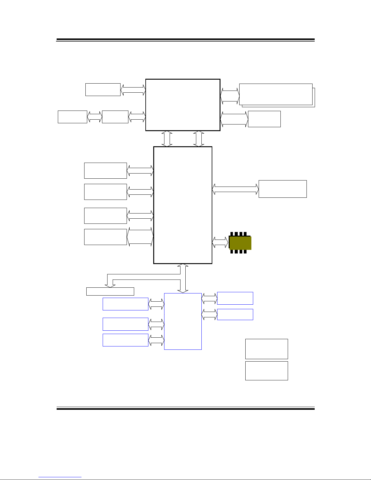
BLOCK DIAGRAM
Dual Channel
Slot *2
SO-DIMM DRAM Modules
USB2.0
ISL95816
Intel
®
4th Gen. Core™
USB 2.0 *6
VR12.5
Lynx Point
F81846AD-I
FDI
FINTEK
LPC SIO
DMI
LGA 1150
LOW PIN COUNT
DDR3
1600
Digital
Display
Interface
USB 3.0 *2
USB3.0
ALC 888S-VD2
High
Definition
Codec
SATA
Connector *3
SATA
3 Phase PWM
COM 1/3/4/5/6
RS232
FAN
Connector
HW monitor
Keyboard
Mouse
H3 Socket
80 port for Debug
COM2
RS232/422/485
Com1/2 support 5V/12V
INTEL PHY-I217LM/V
GIGA LAN1
INTEL Clarkville
PCI-E 1X BUS
PCI-E X16
Slot *1
PCI-E X16
Gen2
R.G.B
from PCH
64Mbit SPI Flash ROM
SPI
SPI
CH7511B
LVDS
Interface
LVDS
Connector
VGA
Connector
TPS51216
For DDR3
Page 89

Appendix B Technical Summary
BM-0947 USER′S MANUAL
Page: B-3
INTERRUPT MAP
IRQ ASSIGNMENT
0 System timer
1 Standard PS/2 Keyboard
3 Communications Port (COM2)
4 Communications Port (COM1)
5 Intel® 8 Series/C220 Series SMBus Controller - 8C22
7 Communications Port (COM3)
7 Communications Port (COM4)
8 System CMOS/real time clock
12 Microsoft PS/2 Mouse
13 Numeric data processor
16 Intel® 8 Series/C220 Series USB EHCI #2 - 8C2D
16 High Definition Audio Controller
19 Intel® 8 Series/C220 Series SATA AHCI Controller - 8C02
22 High Definition Audio Controller
23 Intel® 8 Series/C220 Series USB EHCI #1 - 8C26
81 Microsoft ACPI-Compliant System
82 Microsoft ACPI-Compliant System
83 Microsoft ACPI-Compliant System
84 Microsoft ACPI-Compliant System
85 Microsoft ACPI-Compliant System
86 Microsoft ACPI-Compliant System
87 Microsoft ACPI-Compliant System
88 Microsoft ACPI-Compliant System
89 Microsoft ACPI-Compliant System
90 Microsoft ACPI-Compliant System
91 Microsoft ACPI-Compliant System
92 Microsoft ACPI-Compliant System
93 Microsoft ACPI-Compliant System
94 Microsoft ACPI-Compliant System
95 Microsoft ACPI-Compliant System
Page 90

Appendix B Technical Summary
BM-0947 USER′S MANUAL
Page: B-4
IRQ ASSIGNMENT
96 Microsoft ACPI-Compliant System
97 Microsoft ACPI-Compliant System
98 Microsoft ACPI-Compliant System
99 Microsoft ACPI-Compliant System
100 Microsoft ACPI-Compliant System
101 Microsoft ACPI-Compliant System
102 Microsoft ACPI-Compliant System
103 Microsoft ACPI-Compliant System
104 Microsoft ACPI-Compliant System
105 Microsoft ACPI-Compliant System
106 Microsoft ACPI-Compliant System
107 Microsoft ACPI-Compliant System
108 Microsoft ACPI-Compliant System
109 Microsoft ACPI-Compliant System
110 Microsoft ACPI-Compliant System
111 Microsoft ACPI-Compliant System
112 Microsoft ACPI-Compliant System
113 Microsoft ACPI-Compliant System
114 Microsoft ACPI-Compliant System
115 Microsoft ACPI-Compliant System
116 Microsoft ACPI-Compliant System
117 Microsoft ACPI-Compliant System
118 Microsoft ACPI-Compliant System
119 Microsoft ACPI-Compliant System
120 Microsoft ACPI-Compliant System
121 Microsoft ACPI-Compliant System
122 Microsoft ACPI-Compliant System
123 Microsoft ACPI-Compliant System
124 Microsoft ACPI-Compliant System
125 Microsoft ACPI-Compliant System
126 Microsoft ACPI-Compliant System
127 Microsoft ACPI-Compliant System
Page 91

Appendix B Technical Summary
BM-0947 USER′S MANUAL
Page: B-5
IRQ ASSIGNMENT
128 Microsoft ACPI-Compliant System
129 Microsoft ACPI-Compliant System
130 Microsoft ACPI-Compliant System
131 Microsoft ACPI-Compliant System
132 Microsoft ACPI-Compliant System
133 Microsoft ACPI-Compliant System
134 Microsoft ACPI-Compliant System
135 Microsoft ACPI-Compliant System
136 Microsoft ACPI-Compliant System
137 Microsoft ACPI-Compliant System
138 Microsoft ACPI-Compliant System
139 Microsoft ACPI-Compliant System
140 Microsoft ACPI-Compliant System
141 Microsoft ACPI-Compliant System
142 Microsoft ACPI-Compliant System
143 Microsoft ACPI-Compliant System
144 Microsoft ACPI-Compliant System
145 Microsoft ACPI-Compliant System
146 Microsoft ACPI-Compliant System
147 Microsoft ACPI-Compliant System
148 Microsoft ACPI-Compliant System
149 Microsoft ACPI-Compliant System
150 Microsoft ACPI-Compliant System
151 Microsoft ACPI-Compliant System
152 Microsoft ACPI-Compliant System
153 Microsoft ACPI-Compliant System
154 Microsoft ACPI-Compliant System
155 Microsoft ACPI-Compliant System
156 Microsoft ACPI-Compliant System
157 Microsoft ACPI-Compliant System
158 Microsoft ACPI-Compliant System
159 Microsoft ACPI-Compliant System
Page 92

Appendix B Technical Summary
BM-0947 USER′S MANUAL
Page: B-6
IRQ ASSIGNMENT
160 Microsoft ACPI-Compliant System
161 Microsoft ACPI-Compliant System
162 Microsoft ACPI-Compliant System
163 Microsoft ACPI-Compliant System
164 Microsoft ACPI-Compliant System
165 Microsoft ACPI-Compliant System
166 Microsoft ACPI-Compliant System
167 Microsoft ACPI-Compliant System
168 Microsoft ACPI-Compliant System
169 Microsoft ACPI-Compliant System
170 Microsoft ACPI-Compliant System
171 Microsoft ACPI-Compliant System
172 Microsoft ACPI-Compliant System
173 Microsoft ACPI-Compliant System
174 Microsoft ACPI-Compliant System
175 Microsoft ACPI-Compliant System
176 Microsoft ACPI-Compliant System
177 Microsoft ACPI-Compliant System
178 Microsoft ACPI-Compliant System
179 Microsoft ACPI-Compliant System
180 Microsoft ACPI-Compliant System
181 Microsoft ACPI-Compliant System
182 Microsoft ACPI-Compliant System
183 Microsoft ACPI-Compliant System
184 Microsoft ACPI-Compliant System
185 Microsoft ACPI-Compliant System
186 Microsoft ACPI-Compliant System
187 Microsoft ACPI-Compliant System
188 Microsoft ACPI-Compliant System
189 Microsoft ACPI-Compliant System
190 Microsoft ACPI-Compliant System
4294967283 Intel® I210 Gigabit Network Connection #3
Page 93

Appendix B Technical Summary
BM-0947 USER′S MANUAL
Page: B-7
IRQ ASSIGNMENT
4294967284 Intel® I210 Gigabit Network Connection #3
4294967285 Intel® I210 Gigabit Network Connection #3
4294967286 Intel® I210 Gigabit Network Connection #3
4294967287 Intel® I210 Gigabit Network Connection #3
4294967288 Intel® I210 Gigabit Network Connection #3
4294967289 Intel® Ethernet Connection I217-LM
4294967290 Intel® Management Engine Interface
4294967291 Intel® USB 3.0 eXtensible Host Controller
4294967292 Intel® HD Graphics 4600
4294967293 Intel® 8 Series/C220 Series PCI Express Root Port #4 - 8C16
4294967294 Intel® 8 Series/C220 Series PCI Express Root Port #1 - 8C10
Note: These resource information were gathered on Windows 7 (the IRQ could be
assigned differently depending on your OS.)
Page 94

Appendix B Technical Summary
BM-0947 USER′S MANUAL
Page: B-8
DMA CHANNELS MAP
TIMER CHANNEL ASSIGNMENT
Channel 4 Direct memory access controller
Page 95

Appendix B Technical Summary
BM-0947 USER′S MANUAL
Page: B-9
I/O MAP
I/O MAP ASSIGNMENT
0x00000000-0x0000001F Direct memory access controller
0x00000000-0x0000001F PCI bus
0x00000010-0x0000001F Motherboard resources
0x00000020-0x00000021 Programmable interrupt controller
0x00000022-0x0000003F Motherboard resources
0x00000024-0x00000025 Programmable interrupt controller
0x00000028-0x00000029 Programmable interrupt controller
0x0000002C-0x0000002D Programmable interrupt controller
0x0000002E-0x0000002F Motherboard resources
0x00000030-0x00000031 Programmable interrupt controller
0x00000034-0x00000035 Programmable interrupt controller
0x00000038-0x00000039 Programmable interrupt controller
0x0000003C-0x0000003D Programmable interrupt controller
0x00000040-0x00000043 System timer
0x00000044-0x0000005F Motherboard resources
0x0000004E-0x0000004F Motherboard resources
0x00000050-0x00000053 System timer
0x00000060-0x00000060 Standard PS/2 Keyboard
0x00000061-0x00000061 Motherboard resources
0x00000062-0x00000063 Motherboard resources
0x00000063-0x00000063 Motherboard resources
0x00000064-0x00000064 Standard PS/2 Keyboard
0x00000065-0x0000006F Motherboard resources
0x00000065-0x0000006F Motherboard resources
0x00000067-0x00000067 Motherboard resources
0x00000070-0x00000070 Motherboard resources
0x00000070-0x00000070 System CMOS/real time clock
0x00000072-0x0000007F Motherboard resources
0x00000080-0x00000080 Motherboard resources
0x00000080-0x00000080 Motherboard resources
Page 96

Appendix B Technical Summary
BM-0947 USER′S MANUAL
Page: B-10
I/O MAP ASSIGNMENT
0x00000081-0x00000091 Direct memory access controller
0x00000084-0x00000086 Motherboard resources
0x00000088-0x00000088 Motherboard resources
0x0000008C-0x0000008E Motherboard resources
0x00000090-0x0000009F Motherboard resources
0x00000092-0x00000092 Motherboard resources
0x00000093-0x0000009F Direct memory access controller
0x000000A0-0x000000A1 Programmable interrupt controller
0x000000A2-0x000000BF Motherboard resources
0x000000A4-0x000000A5 Programmable interrupt controller
0x000000A8-0x000000A9 Programmable interrupt controller
0x000000AC-0x000000AD Programmable interrupt controller
0x000000B0-0x000000B1 Programmable interrupt controller
0x000000B2-0x000000B3 Motherboard resources
0x000000B4-0x000000B5 Programmable interrupt controller
0x000000B8-0x000000B9 Programmable interrupt controller
0x000000BC-0x000000BD Programmable interrupt controller
0x000000C0-0x000000DF Direct memory access controller
0x000000E0-0x000000EF Motherboard resources
0x000000F0-0x000000F0 Numeric data processor
0x000002E8-0x000002EF Communications Port (COM4)
0x000002F8-0x000002FF Communications Port (COM2)
0x000003B0-0x000003BB Intel® HD Graphics 4600
0x000003C0-0x000003DF Intel® HD Graphics 4600
0x000003E8-0x000003EF Communications Port (COM3)
0x000003F8-0x000003FF Communications Port (COM1)
0x000004D0-0x000004D1 Motherboard resources
0x000004D0-0x000004D1 Programmable interrupt controller
0x00000680-0x0000069F Motherboard resources
0x00000A00-0x00000A0F Motherboard resources
0x00000A10-0x00000A1F Motherboard resources
0x00000A20-0x00000A2F Motherboard resources
Page 97

Appendix B Technical Summary
BM-0947 USER′S MANUAL
Page: B-11
I/O MAP ASSIGNMENT
0x00000D00-0x0000FFFF PCI bus
0x0000164E-0x0000164F Motherboard resources
0x00001800-0x000018FE Motherboard resources
0x00001854-0x00001857 Motherboard resources
0x00001C00-0x00001CFE Motherboard resources
0x00001D00-0x00001DFE Motherboard resources
0x00001E00-0x00001EFE Motherboard resources
0x00001F00-0x00001FFE Motherboard resources
0x0000E000-0x0000EFFF Intel® 8 Series/C220 Series PCI Express Root Port
#4 - 8C16
0x0000F000-0x0000F03F Intel® HD Graphics 4600
0x0000F040-0x0000F05F Intel® 8 Series/C220 Series SMBus Controller -
8C22
0x0000F060-0x0000F07F Intel® 8 Series/C220 Series SATA AHCI Controller
- 8C02
0x0000F0A0-0x0000F0A3 Intel® 8 Series/C220 Series SATA AHCI Controller
- 8C02
0x0000F0B0-0x0000F0B7 Intel® 8 Series/C220 Series SATA AHCI Controller
- 8C02
0x0000F0C0-0x0000F0C3 Intel® 8 Series/C220 Series SATA AHCI Controller
- 8C02
0x0000F0D0-0x0000F0D7 Intel® 8 Series/C220 Series SATA AHCI Controller
- 8C02
0x0000FFFF-0x0000FFFF Motherboard resources
0x0000FFFF-0x0000FFFF Motherboard resources
0x0000FFFF-0x0000FFFF Motherboard resources
Page 98

Appendix B Technical Summary
BM-0947 USER′S MANUAL
Page: B-12
MEMORY MAP
MEMORY MAP ASSIGNMENT
0xFED40000-0xFED44FFF System board
0xFED1C000-0xFED1FFFF Motherboard resources
0xFED10000-0xFED17FFF Motherboard resources
0xFED18000-0xFED18FFF Motherboard resources
0xFED19000-0xFED19FFF Motherboard resources
0xF8000000-0xFBFFFFFF Motherboard resources
0xFED20000-0xFED3FFFF Motherboard resources
0xFED90000-0xFED93FFF Motherboard resources
0xFED45000-0xFED8FFFF Motherboard resources
0xFF000000-0xFFFFFFFF Motherboard resources
0xFF000000-0xFFFFFFFF Intel® 82802 Firmware Hub Device
0xFEE00000-0xFEEFFFFF Motherboard resources
0xF7FDF000-0xF7FDFFFF Motherboard resources
0xF7FE0000-0xF7FEFFFF Motherboard resources
0xF7C00000-0xF7C7FFFF Intel® I210 Gigabit Network Connection #3
0xF7C00000-0xF7C7FFFF Intel® 8 Series/C220 Series PCI Express Root Port
#4 - 8C16
0xF7C80000-0xF7C83FFF Intel® I210 Gigabit Network Connection #3
0xF7D3B000-0xF7D3B3FF Intel® 8 Series/C220 Series USB EHCI #1 - 8C26
0xF7D3C000-0xF7D3C3FF Intel® 8 Series/C220 Series USB EHCI #2 - 8C2D
0xF7D00000-0xF7D1FFFF Intel® Ethernet Connection I217-LM
0xF7D3D000-0xF7D3DFFF Intel® Ethernet Connection I217-LM
0xF7D20000-0xF7D2FFFF Intel® USB 3.0 eXtensible Host Controller
0xF7D3A000-0xF7D3A7FF Intel® 8 Series/C220 Series SATA AHCI
Controller - 8C02
0xF7D3F000-0xF7D3F00F Intel® Management Engine Interface
0xFED00000-0xFED003FF High precision event timer
0xF7800000-0xF7BFFFFF Intel® HD Graphics 4600
0xE0000000-0xEFFFFFFF Intel® HD Graphics 4600
0xF7D34000-0xF7D37FFF High Definition Audio Controller
Page 99
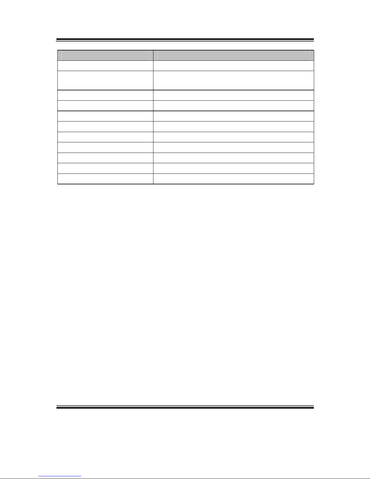
Appendix B Technical Summary
BM-0947 USER′S MANUAL
Page: B-13
MEMORY MAP ASSIGNMENT
0xF7D30000-0xF7D33FFF High Definition Audio Controller
0xF7D39000-0xF7D390FF Intel® 8 Series/C220 Series SMBus Controller -
8C22
0xA0000-0xBFFFF Intel® HD Graphics 4600
0xA0000-0xBFFFF PCI bus
0xD0000-0xD3FFF PCI bus
0xD4000-0xD7FFF PCI bus
0xD8000-0xDBFFF PCI bus
0xDC000-0xDFFFF PCI bus
0xE0000-0xE3FFF PCI bus
0xE4000-0xE7FFF PCI bus
0x3E200000-0xFEAFFFFF PCI bus
Page 100

Appendix B Technical Summary
BM-0947 USER′S MANUAL
Page: B-14
WATCHDOG TIMER CONFIGURATION
The I/O port address of the watchdog timer is 2E (hex) and 2F (hex). 2E (hex) is the
address port. 2F (hex) is the data port. User must first assign the address of register by
writing address value into address port 2E (hex), then write/read data to/from the
assigned register through data port 2F (hex).
Configuration Sequence
To program F81866 configuration registers, the following configuration sequence
must be followed:
1. Enter the extended function mode
To place the chip into the Extended Function Mode, two successive writes of 0x87
must be applied to Extended Function Enable Registers (EFERs, i.e. 2Eh or 4Eh).
2. Configure the configuration registers
The chip selects the Logical Device and activates the desired Logical Devices through
Extended Function Index Register (EFIR) and Extended Function Data Register
(EFDR). The EFIR is located at the same address as the EFER, and the EFDR is
located at address (EFIR+1). First, write the Logical Device Number (i.e. 0x07) to the
EFIR and then write the number of the desired Logical Device to the EFDR. If
accessing the Chip (Global) Control Registers, this step is not required. Secondly,
write the address of the desired configuration register within the Logical Device to the
EFIR and then write (or read) the desired configuration register through the EFDR.
3. Exit the extended function mode
To exit the Extended Function Mode, writing 0xAA to the EFER is required. Once the
chip exits the Extended Function Mode, it is in the normal running mode and is ready
to enter the configuration mode.
 Loading...