

Page 1

MANUAL
PA-6722
15" POS Terminal
Powered by Intel Celeron
J1900 Quad-Cord
PA-6722 M6
Page 2

CHAPTER
INTRODUCTION
This chapter gives you the information for the PA-6722. It also outlines
the system specification
Sections included:
About This Manual
POS System Illustration
System Specifications
Safety precautions
Experienced users can jump to chapter 2 on page 2-1
for a quick start.
s.
1
Page 3

COPYRIGHT NOTICE & TRADEMARK
Page.3
All trademarks and registered trademarks mentioned herein are the property of their
respective owners.
This manual is copyrighted June 2014. You may not reproduce or transmit in any
form or by any means, electronic, or mechanical, including photocopying and
recording.
DISCLAIMER
This user’s manual is meant to assist users in installing and setting up the system. The
information contained in this document is subject to change without any notice.
CE NOTICE
This is a class A product. In a domestic environment this product may cause radio
interference in which case the user may be required to take adequate measures.
FCC NOTICE
This equipment has been tested and found to comply with the limits for a Class A
di
gital device, pursuant to part 15 of the FCC Rules. These limits are designed to
provide reasonable protection against harmful interference when the equipment is
operated in a commercial environment. This equipment generates, uses, and can
radiate radio frequency energy and, if not installed and used in accordance with the
instruction manual, may cause harmful interference to radio communications.
Operation of this equipment in a residential area is likely to cause harmful interference
in which case the user will be required to correct the interference at his own expense.
You are cautioned that any change or modifications to the equipment not expressly
approve by the party responsible for compliance could void your authority to operate
such equipment.
CAUTION! Danger of explosion if battery is incorrectly replaced. Replace only with the
same or equivalent type recommended by the manufacturer. Dispose of used batteries
according to the manufacturer’s instructions.
WARNING! Some internal parts of the system may have high electrical voltage. And
therefore we strongly recommend that qualified engineers can open and disassemble the
system.The LCD and Touchscreen are easily breakable, please handle them with extra
care.
Page 4

1-1. ABOUT THIS MANUAL
Page.4
Thank you for purchasing our PA-6722 Series System. The PA-6722 is an updated
system designed to be comparable with the highest performance of IBM AT personal
computers. The PA-6722 provides faster processing speed, greater expandability and
can handle more tasks than before. This manual is designed to assist you how to install
and set up the whole system. It contains four chapters and two appendixes. Users can
configure the system according to their own needs.
Chapter 1 Introduction
This chapter introduces you to the background of this manual. It also includes
illustrations and specifications for the whole system. The final section of this chapter
indicates some safety reminders on how to take care of your system.
Chapter 2 System Configuration
This chapter outlines the location of motherboard, printer, VFD, MSR components
and their function. You will learn how to set the jumpers and configure the system to
meet your own needs.
Chapter 3 Software
This chapter contains detailed information for driver installations of the Intel® Utility,
VG, LAN, Sound, Touch Screen, embedded peripheral devices, BIOS setup & update,
Watchdog timer and resource map.
Chapter 4 System Diagrams
This chapter shows the exploded diagrams and part numbers of PA-6722 components.
Page 5
Page.5
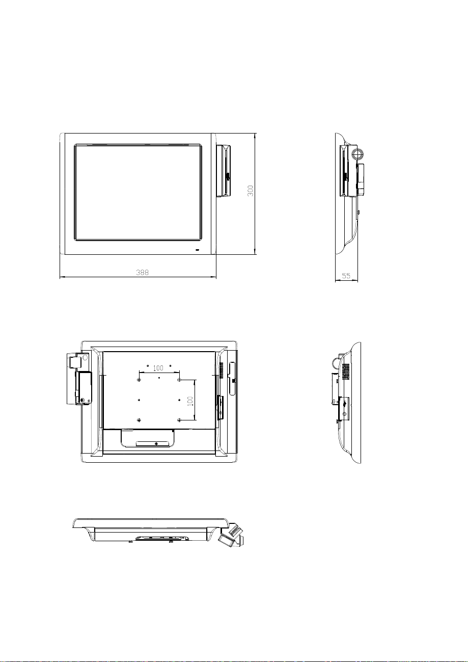
Panel-PC
Page 6
Page.6
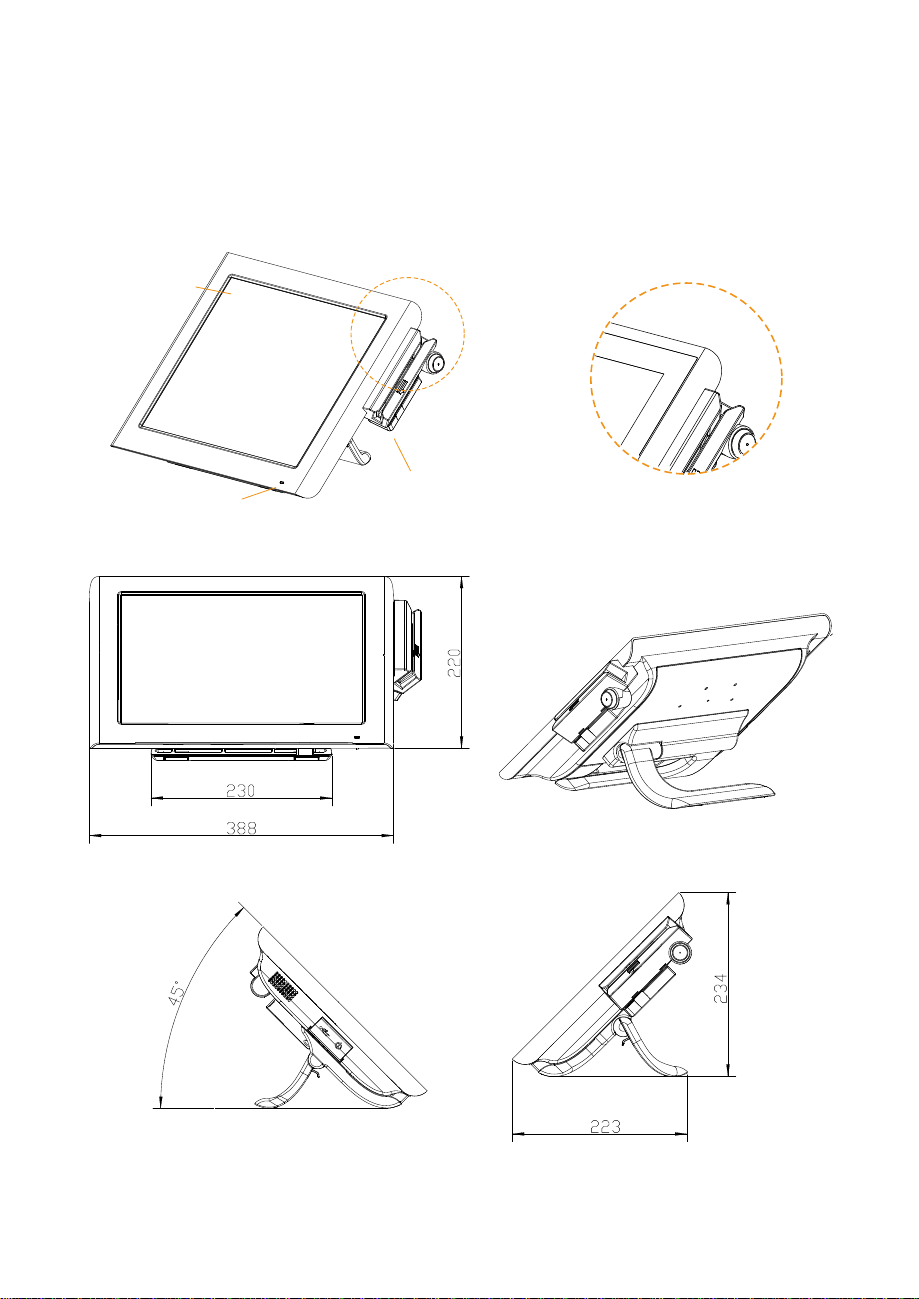
Easy Stand
Non-bazel-free
Bezel-free TouchScreen
15" Touch
& LCD
Power
LED light
Stand
Optional MSR & iButton
Adjustable angle
30~50 degrees
Page 7
Page.7
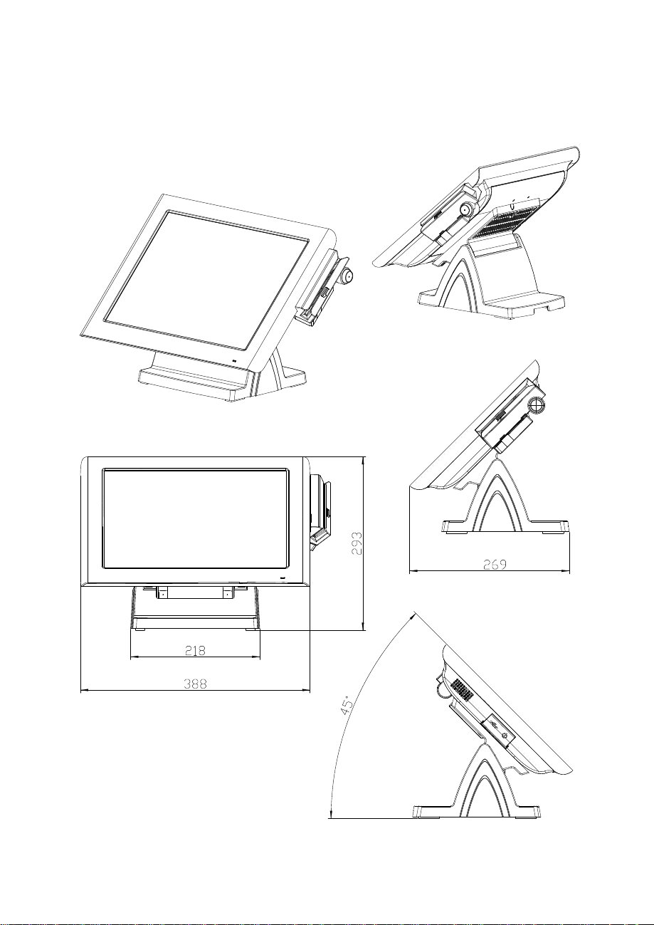
Small Stand
Adjustable angle
0~70 degrees
Page 8
Page.8
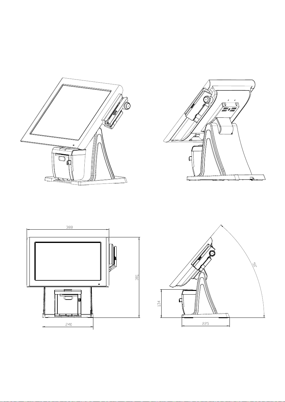
PRINTER Stand
Page 9
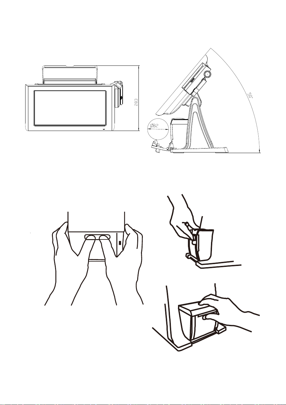
Caution:
Page.9
The correct method of "Closing Printer-Door". Please refer to below drawings.
Page 10
1-3. SYSTEM SPECIFICATIONS
Page.10
System
CPU
Intel® Celero
n® J1900 Quad
-
Core 2.0GHz
Memory 1 x DDR3/ SO-DIMM 204-pin socket, up to 8GB
OS Support Windows Embedded 8 Industry Pro Retail
WindowV Embedded POSReady7
LAN 1 x Giga LAN
VGA 1 x DB-15
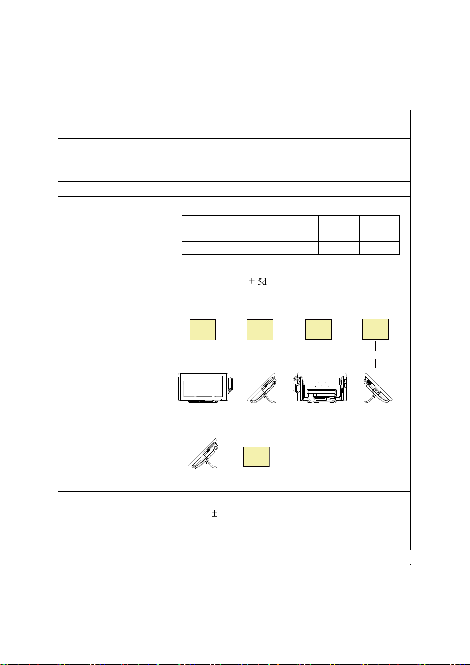
Wireless LAN (Optional) 802.11 b/g/n
AP distance 0° 90° 180° 270°
5M
10M
Note:
1. Test tolerance:
2. AP: ASUS RT-N56U (2 x internal antenna with 3.8 dBi
gain)
AP
(Distance)
-29 dB -29 dB -30 dB -29 dB
-30 dB -30 dB -31 dB -31 dB
± 5dB
AP
(Distance)
AP
(Distance)
AP
(Distance)
Angle: 0°
Angle: 90°
Angle: 180° Angle: 270°
AP
Audio 2W speaker & Line-out Port
BIOS AMI SPI BIOS, 8 Mbits with VGA BIOS
RTC Accuracy 3 days
System Weight
Dimension (W x H x D)
±
3 seconds
With power adapter approx. 5.5 kg
388mm x 223mm x 234mm
Page 11

Power Consumption (AC):
Page.11
Power Supply: 60~90 Watt power adapter
System
status
OFF ODLE
w/o Printer
WORKING
with Printer
Burn-in Test
loading Set
/CPU /HDD
Shut down standby 100%
/MEMORY
USB - - 5V x4 ports with dummy
COM - -
12V x2 ports with dummy
5V x1 ports with dummy
with
For Printer - -
-
24V/1.2A
printer
running
Power
Consumption
AC 1.3W AC 20.4W
AC 58W
AC 88W
Certificate: CE, CE-LVD, FCC
Type Standard Description
EMI EN 55022 Class A EMS EN 55024 IEC 61000-4-2 ESD 8kV air discharge
4kV contact discharge
IEC 61000-4-3 RS 80~1000MHz, 3V/m, 80% AM(1kHz)
IEC 61000-4-4 EFT AC Power Port: 1kV
DC Power Port: 0.5kV
Signal Ports & Telecommunication
Ports: 0.5kV
IEC 61000-4-5 Surge AC Power Port:
Line to line: 1kV
Line to earth(GND): 2kV
DC Power Port:
Line to earth(GND): 0.5kV
Signal and Telecommunication Port:
Line to GND: 1kV
IEC 61000-4-6 CS 0.15~80MHz, 3Vrms, 80% AM, 1kHz
IEC 61000-4-8 PFMF 50Hz, 1A/m
IEC 61000-4-11
Voltage Dips > 95% reduction for 0.5 periods
30% reduction for 25 periods
Voltage Interruptions > 95% reduction for 250 periods
Page 12
Display
Page.12
Resistive TouchScreen
Projected Capacitive TouchScreen
15” TFT XGA LCD Max. Resolution: 1024 x 768
Signal Interface: TTL (24-bit)
Touchscreen
15”
5-wire resistive type
Projected capacitive type
Brightness
Minimum
1
4
2
3
5
160 cd/m
Minimum
180 cd/m
2
2
Environment
Temperature
Operating: 0 ~ 35°C (32 ~ 95°F)
Storage: -5 ~ 60°C (-27 ~ 140°F)
Humidity 20~90%
Page 13
Optional accessories
Page.13
Standard Code
CP-437, Katakana, CP-737, CP-850, CP-852,
CP-857, CP-860, CP-862, CP-863,CP-865,
CP-866, CP-1250, CP-1251, CP-1252, CP-1253,
CP-1254, CP-1255, CP-1257,
International Characters
USA, FRANCE, GERMANY, UK, DENMARK I,
SWDEN, ITALY, SPAIN I, JAPAN, NORWAY,
DENMARK II, SPAIN II, LATIN, KOREA, RUSSIA,
SLAVONIC
MSR & i-Button ISO I ,II, III; JIS I,II and support information key reader
RFID ISO14443A, Mifare, Felica-lite
Fingerprint 8-bit grayscale reader
2nd Display 8” LCD (Resolution: 800 x 600)
10.4” LCD (Resolution: 1024 x 768 or 800 x 600)
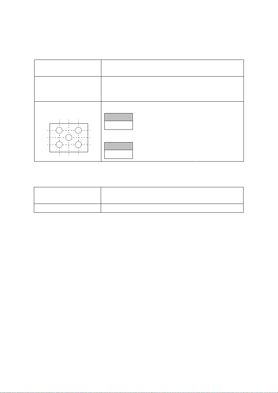
Customer Display
Interface: RS-232C Baud Rate: 9600/19200 bps
Placement: 20 columns and 2 lines, each column is 5
x 7 dots
3.75
0.8
0.55
0.75
1.0
6.75
Page 14
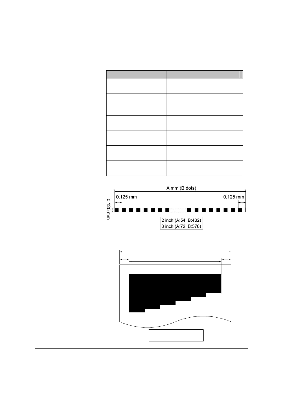
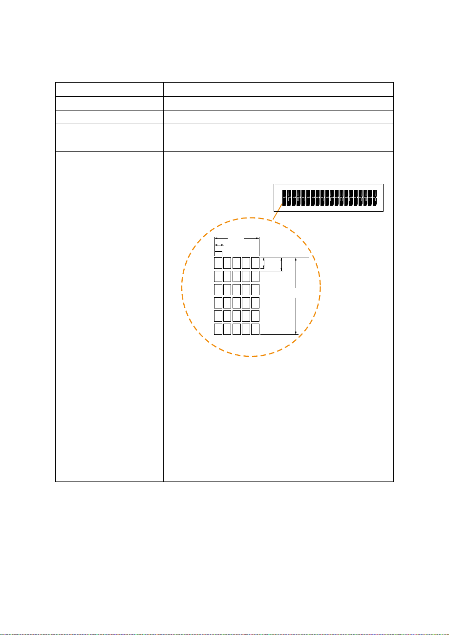
Printer 2” or 3” easy loading thermal printer with auto-cutter
0
Page.14
Printer:
Items Specifications
Printing method Thermal dot line printing
Printing accuracy 1mm /5M
Paper feed pitch 0.0625 mm
Maximum Paper-Roll
thickness
Total dots per line &
Printable dots per line
Maximum print speed 2inch 200 mm/s;
Print width 2inch 54 mm;
Paper width 2inch 58 +0/-1 mm;
80mm
2inch 432 dots;
3inch 576 dots
3inch 170 mm/s
3inch 72mm
3inch 80 +0/-1 mm
D mm
C
-1 mm (Paper Width)
A mm (Printing Width)
2 inch (A:54, C:58, D:2)
3 inch (A:72, C:80, D:4)
D mm
Page 15

Printer Auto-cutter:
Page.15
Items Specifications
Paper cutting method Slide cutting
Type of paper cutting Full cut and Partial cut (1.5 ±
Paper curling tendency Fixed blade side and Movable
Minimum paper core
diameter
Minimum paper cutting
length
Cutting processing time Approx. 0.5 s/cycle
Cutting frequency 1 cut/2 s max.
Standard Code
CP-437, CP-850, CP-857, CP-737, CP-852, CP-860,
CP-862, CP-863, CP-865, CP-866, CP-1250,
CP-1251, CP-1252, CP-1253, CP-1254, CP-1257,
Katakana
KANJI
JAPANESE (SHIFT-JIS) Code,
TRADITIONAL CHINESE Code
0.5 mm tab left at the center)
blade side
φ8 mm (paper thickness: 75µm
or thin)
φ18 (paper thickness: thicker
than 75µm)
10 mm
International Characters
USA, FRANCE, GERMANY, UK, DENMARK I,
SWDEN, ITALY, SPAIN I, JAPAN, NORWAY,
DENMARK II, SPAIN II, LATIN AMERICA,
KOREA, RUSSIA, SLAVONIC
Page 16

1-4. SAFETY PRECAUTIONS
Page.16
The following messages are safety reminders on how to protect your systems from
damages, and extending the life cycle of the system.
1. Check the Line Voltage
a. The operating voltage for the power supply should be within the range of
100V to 240V AC; otherwise the system may be damaged.
2. Environmental Conditions
a. Place your PA-6722 on a sturdy, level surface. Be sure to allow enough
space around the system to have easy access needs.
b. Avoid installing your PA-6722 Series POS system in extremely hot or cold
places.
c. Avoid exposure to sunlight for a long period of time (for example, in a
closed car in summer time. Also avoid the system from any heating device.).
Or do not use the PA-6722 when it has been left outdoors in a cold winter
day.
d. Bear in mind that the operating ambient temperature is between 0°C and
35°C (32°F and 95°F).
e. Avoid moving the system rapidly from a hot place to a cold place, and vice
versa, because condensation may occur inside the system.
f. Protect your PA-6722 against strong vibrations, which may cause hard disk
failure.
g. Do not place the system too close to any radio-active device. Radio-active
device may cause signal interference.
h. Always shutdown the operation system before turning off the power.
3. Handling
a. Avoid placing heavy objects on the top of the system.
b. Do not turn the system upside down. This may cause the hard drive to
malfunction.
c. Do not allow any objects to fall into this product.
d. If water or other liquid spills into the product, unplug the power cord
immediately.
Page 17

SYSTEM
CONFIGURATION
Helpful information that describes the jumper and connector settings,
component locations, and pin assignment.
Sections included:
External I/O Port Pin Assignment
How to Set Jumpers
CHAPTER
2
Component Locations & Jumper S
- Mainboard
- Printer Board (peripheral device)
- VFD Board (peripheral device)
- MSR Board (peripheral device)
Secondary Cash Drawer Port
ettings
Page 18
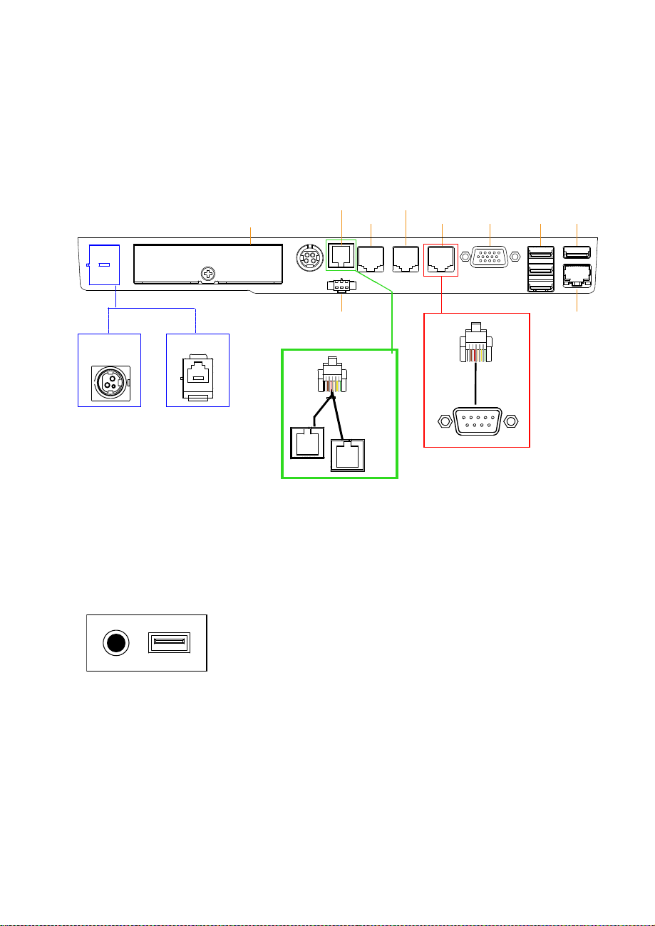
2-1. SYSTEM EXTERNAL I/O PORT & PIN ASSIGNMENT
Page.18
Rear I/O
PRINT
PWR
Side I/O
COM4
HDD
DRW
1-2
DRW1
2ND-DIS
COM3
PWR
RJ11
DRW1-1
COM2
COM1
COM
VGA
RJ45
USB
2/3/4
USB1
LAN
Power USB5
button
Page 19
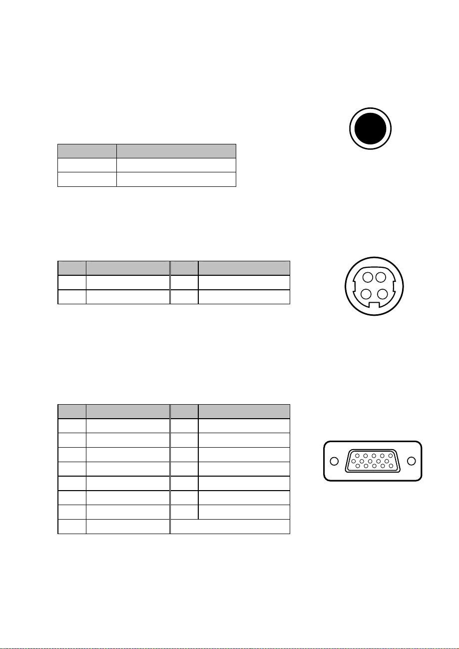
Power Button
Page.19
To turn on the system, press the power button on the side
of the system briefly.
ACTION ASSIGNMENT
Click 0V
Release +3.3V
DC-IN Port
DC IN: DC Power-In Port (rear IO)
Power
Button
PIN ASSIGNMENT PIN ASSIGNMENT
1 GND 3 +24V
2 GND 4 +24V
VGA Port
VGA: VGA Port, D-Sub 15-pin (rear IO)
PIN ASSIGNMENT PIN ASSIGNMENT
1 RED 9 +5V
2 GREEN 10 GND
3 BLUE 11 NC
4 NC 12 DDCA DATA
5 GND 13 HSYNC
6 GND 14 VSYNC
7 GND 15 DDCA CLK
8 GND
1 2
3 4
DC IN
11 15
6 10
1 5
VGA
Page 20
COM Port
Page.20
USB 1
/USB 2
/USB 3
/USB 4
/USB 5
COM 1
/COM 2
/COM 3
/COM 4
(option)
COM1, COM2, COM3: COM Ports (rear IO)
PIN ASSIGNMENT PIN ASSIGNMENT
1 DCD1/2/3 6 DSR1/2/3
2 RXD1/2/3 7 RTS1/2/3
3 TXD1/2/3 8 CTS1/2/3
RI/+5V/+12V
4
DTR1/2/3
5 GND 10 NC
9
selectable
(Maximum
current: 1A)
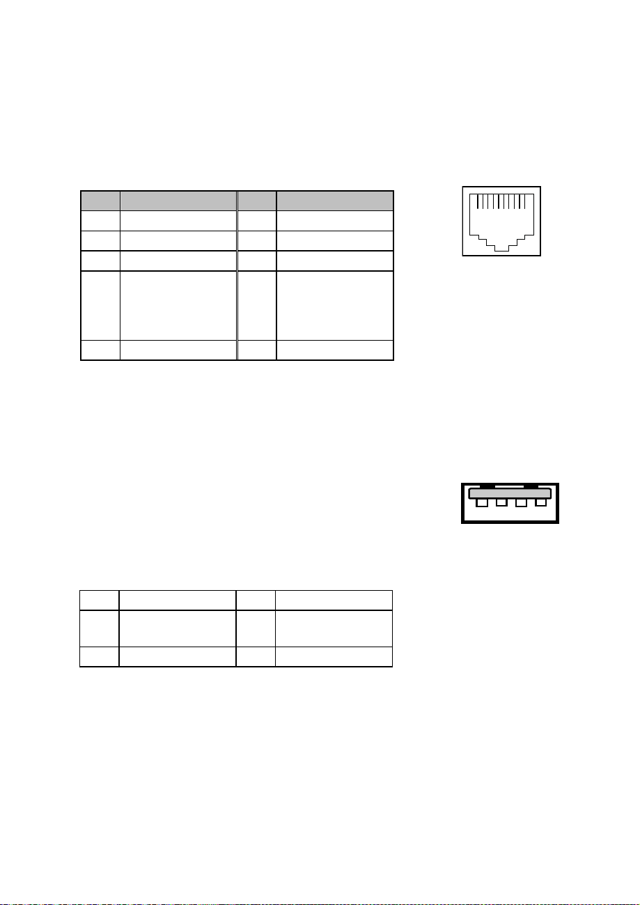
USB Port
USB1, USB2, USB3, USB4, USB5: USB Type A Ports
USB 1~4: Rear I/O
USB 5: Side IO
PIN ASSIGNMENT PIN
+5V (Max.
1
current: 0.5A)
2 D- 4 GND
ASSIGNMENT
D+
3
101
1 4
Note:
USB1 with Standby power 5V. the Others are w/o standby power.
Page 21
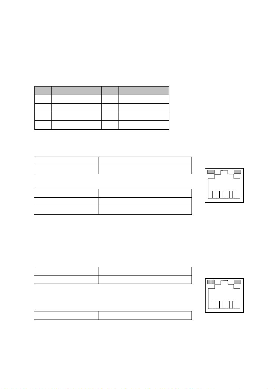
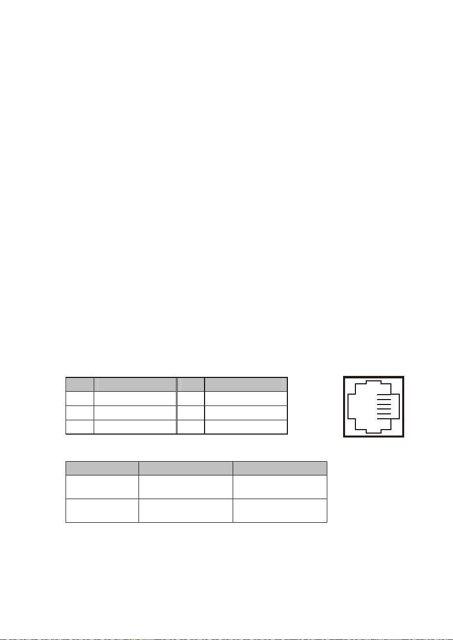
LAN Port
Page.21
LAN: LAN RJ45 Port (rear IO)
PIN ASSIGNMENT PIN ASSIGNMENT
1 MDIP0 5 MDIP2
2 MDIN0 6 MDIN2
3 MDIP1 7 MDIP3
4 MDIN1 8 MDIN3
LAN LED Indicator:
Left Side LED
Yellow Color Blinking LAN Message Active
Off No LAN Message Active
Right Side LED
Green Color On 10/100Mbps LAN Speed Indicator
Orange Color on Giga LAN Speed Indicator
Off No LAN switch/ hub connected.
LAN LED Indicator:
Left Side LED
Orange Color Blinking Giga LAN Message Active
Green Color Blinking
Right Side LED
Green Color On
RA Ver.
RB Ver.
10/100Mbps LAN Message Active
LAN switch/ hub connected.
Yellow Green
8 1
LAN
Left:Orange
Right:Green
Green
8 1
LAN
Page 22
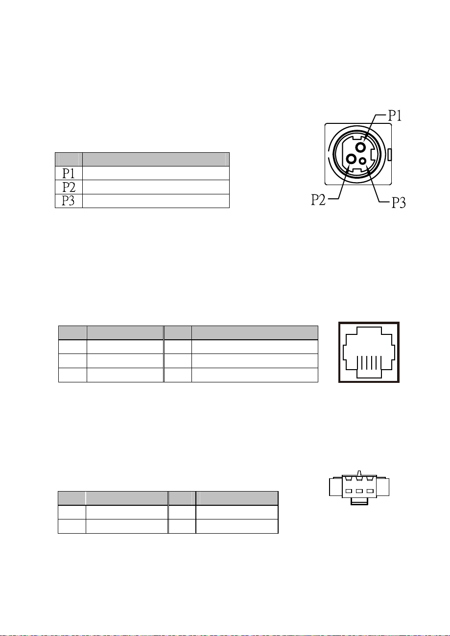
Printer Power Port (Optional)
Page.22
6 1
DRW1
PRINT
POWER
PRINT PWR: DC24V power supply for the stand-printer
PIN ASSIGNMENT
+24V
+24V
GND
Cash Drawer Port
DRW1 is used by default. If you need a second port, adopt the method below.
PIN ASSIGNMENT PIN ASSIGNMENT
1
DRW2 Sense
2
GPIO1 /DRW1
3
DRW1 Sense
Please refer to page.27 for detail of DRW2 port.
4
12V/24V (Max. current 1A)
5
GPIO2 /DRW2
6 GND
2nd Display Power Port
2ND DIS PWR: DC12V power supply of for 2nd display
PIN ASSIGNMENT PIN ASSIGNMENT
1 VCC12 3 VCC12
2 GND
1 3
2ND DIS PWR
Page 23
1
Page.23
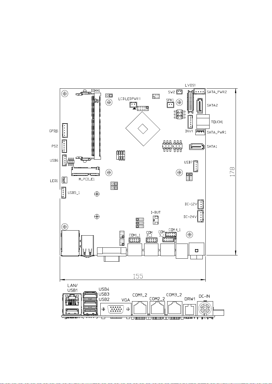
2-2. MAINBOARD COMPONENT LOCATIONS & JUMPER
SETTINGS
M/B: PB-6722
JP13
2
1
JP1JP1
1
77 11
6
5
22
JPJP44
JP19
216
5
9
1
JP18
2
10
JP5
1
5
JP17
2
22
6
1
11
5
JP6
1
2
6
6
5
1 1
JP2
JP_COM3
JP_COM2
1
JP3
1
JP10
JP11
JP12
5
6
1
2
5
6
1
2
JP8
1
JP15
JP9
PB-6722 Mainboard Component Locations
Page 24
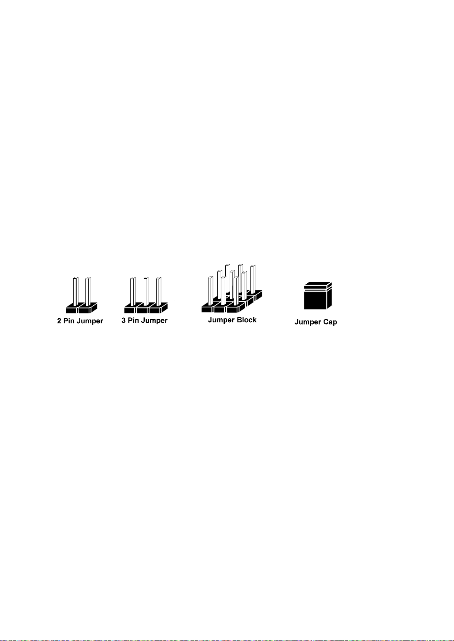
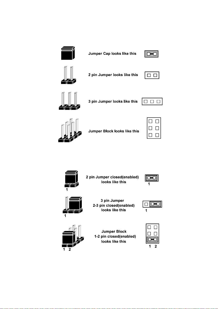
2-2-1. How to Set Jumpers
Page.24
You can configure your board by setting the jumpers. A jumper consists of two or three
metal pins with a plastic base mounted on the card, and by using a small plastic "cap",
also known as the jumper cap (with a metal contact inside), you are able to connect the
pins. So you can set-up your hardware configuration by "opening" or "closing" pins.
Jumpers can be combined into sets that called jumper blocks. When jumpers are all in
the block, you have to put them together to set up the hardware configuration. The
figure below shows what this looks like.
Jumpers & caps
If a jumper has three pins for example, labelled PIN1, PIN2, and PIN3. You can
connect PIN1 & PIN2 to create one setting and shorting. You can either connect PIN2
& PIN3 to create another setting. The same jumper diagrams are applied all through
this manual. The figure below shows what the manual diagrams look and what they
represent.
Page 25
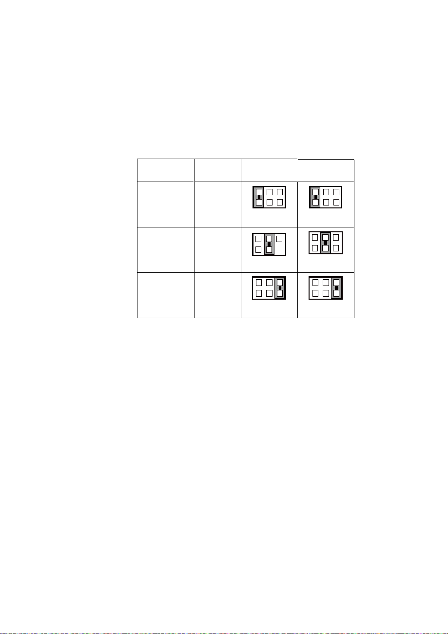
Jumper diagrams
Page.25
Jumper settings
Page 26
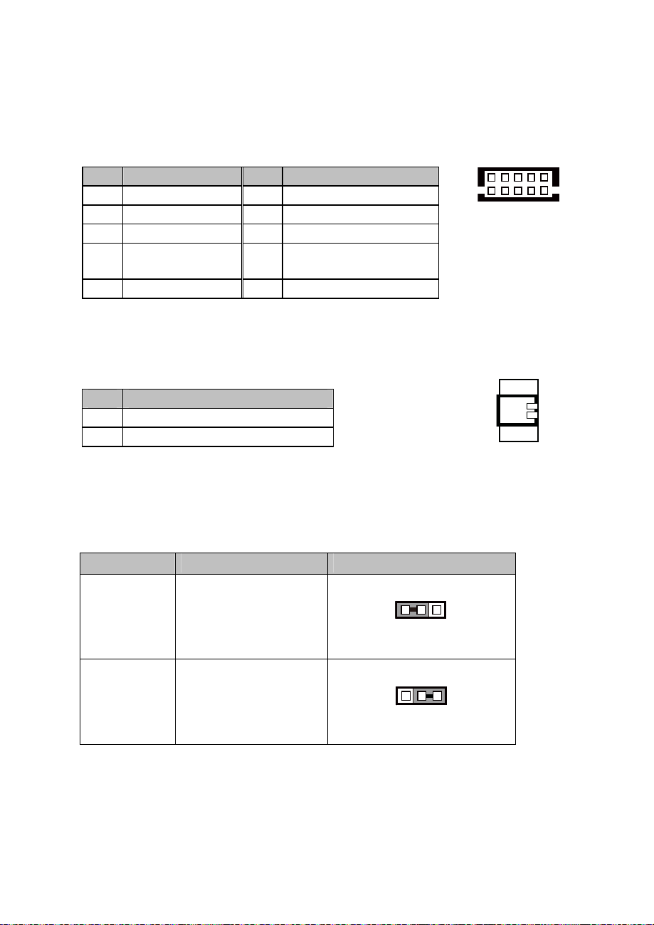
COM, Cash Drawer Port voltage selection
Page.26
COM2 / COM3
Voltage of both COM2 & COM3 ports are made to control by jumpers
on board
COM1 / COM4 /DRW1
Voltage of external ports "COM1 & COM4 & Cash Drawer" are made
to control on BIOS for your convenience
JP_COM2, JP_COM3: Pin-headers on board
SELECTION
RI 1-2
+12V 3-4
+5V 5-6
JUMPER
SETTING
JUMPER ILLUSTRATION
2
1
JP_COM2
2
1
JP_COM2
2
1
JP_COM2
6
5
6
5
6
5
2
1
JP_COM3
2
1
JP_COM3
2
1
2
1
JP_COM3
6
5
6
5
6
5
Page 27
COM Connector
Page.27
JP10 /JP11 /JP12
I-BUT
JP10 /JP11 /JP12
COM1-1, COM2-1, COM3-1, COM4-1: COM Connectors
PIN ASSIGNMENT PIN ASSIGNMENT
1 DCD 6 DSR
2 RXD 7 RTS
3 TXD 8 CTS
DTR
4
5 GND
RI/+5V/+12V selectable
9
(Max. current: 1A)
10 NC
6
COM1-1/
COM2-1/
COM3-1/
COM4-1/
I-Button Connector
I-BUT: i-Button Connector
PIN ASSIGNMENT
1 COM2_DTR_R_I
2 COM2_RXD_R_I
I-Button Function Selection
JP10, JP11, JP12: i-Button Function Connectors
SELECTION JUMPER SETTING JUMPER ILLUSTRATION
10
51
2
1
Note: Manufacturing Default is COM2.
*COM2 & COM2-1 will not function when jumpers JP10, JP11 & JP12 are
1 3
COM2 1-2
1 3
I-BUT 2-3
set as “I_BUT”
Page 28
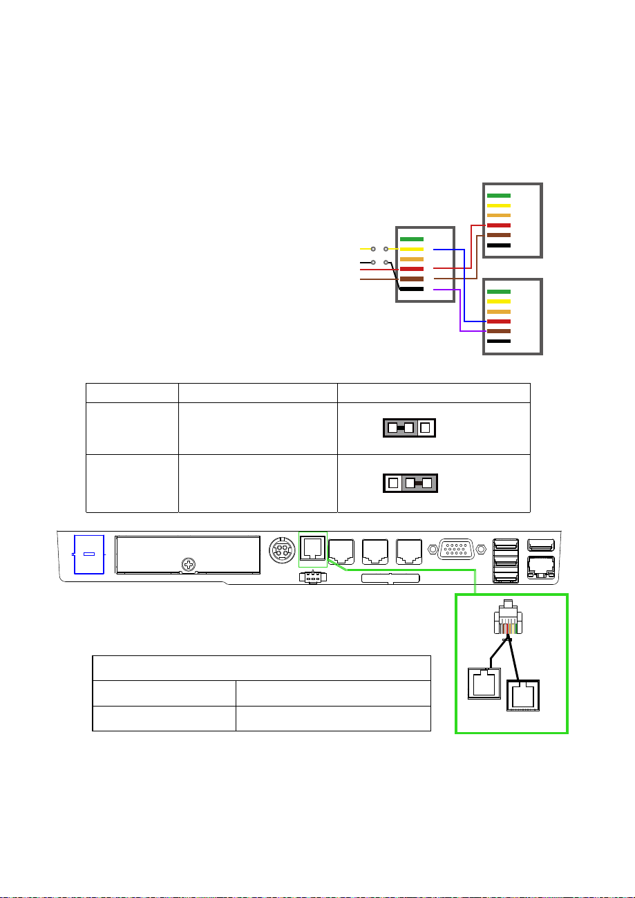
DRW1, DRW1-1, DRW1-2
Page.28
Step.1
DRW1 includes two groups of GPIO pins. The
second group is normally unused but can be
enabled by the jumper.
Set the pin-header jumper JP15 as 1-2
DRW1 is used by default. If you need a second port, adopt either way below.
1
1
JP15
JP15
Step.2
You can split DRW1 into two channels of DRW1-1 &
DRW1-2 with the Y-Cable(option).
Step.3
DRW1, DRW1-1, DRW1-2 shares the same power
source (Default at 12V).
(Connect
h
wit
Y-cable)
DRW1
GPIO2
JP15
GPIO1
6
5
4
3
2
1
.
JP15
SELECTION JUMPER SETTING JUMPER ILLUSTRATION
DRW1-1 &
DRW1-2
DRW1 only 2-3
1-2
DRW1-1
6
5
4
3
2
1
DRW1-2
6
5
4
3
2
1
SIO address
Cash drawer 1 LDN 06, 0x91 bit 2
Cash drawer 2 LDN 06, 0x91 bit 3
DRW
1-2
DRW1
DRW1-1
Page 29

CASH DRAWER CONFIGURATION
Page.29
The I/O port address of the cash drawer is 2E (hex) and 2F (hex). 2E (hex) is the address port. 2F (hex) is the
data port. User must first assign the address of register by writing address value into address port 2E (hex),
then write/read data to/from the assigned register through data port 2F (hex).
Configuration Sequence
To program F81866 configuration registers, the following configuration sequence must be followed:
(1) Enter the extended function mode
(2) Configure the configuration registers
(3) Exit the extended function mode
(1) Enter the extended function mode
To place the chip into the Extended Function Mode, two successive writes of 0x87 must be applied to
Extended Function Enable Registers (EFERs, i.e. 2Eh or 4Eh).
(2) Configure the configuration registers
The chip selects the Logical Device and activates the desired Logical Devices through Extended Function
Index Register (EFIR) and Extended Function Data Register (EFDR). The EFIR is located at the same
address as the EFER, and the EFDR is located at address (EFIR+1). First, write the Logical Device Number
(i.e. 0x06) to the EFIR and then write the number of the desired Logical Device to the EFDR. If accessing the
Chip (Global) Control Registers, this step is not required. Secondly, write the address of the desired
configuration register within the Logical Device to the EFIR and then write (or read) the desired configuration
register through the EFDR.
(3) Exit the extended function mode
To exit the Extended Function Mode, writing 0xAA to the EFER is required. Once the chip exits the Extended
Function Mode, it is in the normal running mode and is ready to enter the configuration mode.
Code example for open the cash drawer 1
;------ Enter to extended function mode --------------------------------------------------------
mov dx, 2eh
mov al, 87h
out dx, al
out dx, al
;------ Select Logical Device 6 of Cash drawer --------------------------------------------
mov al, 07h
out dx, al
inc dx
mov al, 06h
out dx, al
dec dx
;------ Open the Cash drawer 1 --------------------------------------------
mov al, 91h
out dx, al
inc dx
mov al, 04h
out dx, al
;------ Exit the extended function mode --------------------------------------------------------
dec dx
mov al, 0aah
out dx, al
Page 30
PIN ASSIGNMENT PIN ASSIGNMENT
Page.30
Notice:
DRW2 Port (Only support PA-6722 selected "Printer kit")
Signal from printer board (MB-1030, MB-1011(3), PDAC3100) and be controlled by
command. DRW2 port on the bottom of Stand with a cable (optional).
Bottom View
GND
1
2 Drawer Open 5 NC
3 Drawer Sense 6 GND
Control Codes Hexadecimal Codes Function
<DLE EOT> 10 04
<DLE DC4>
10 14
4 +24V
Real-time status
transmission
Real-time output of
specified pulse
1
6
DRW2
Page 31

USB Connector
Page.31
USB 5_1
/USB 6
/USB 7
Note:
USB6 signal is shared from "MINI-PCIE" port.
USB6 could be functioned when JP13 are set 1-3, 2-4 [short].
USB7 signal is shared from "Touch Controller"
USB7 could be functioned when JP8, JP9 are set 1-2 [short].
SPK1
LED1
USB5_1, USB6, USB7: USB 2.0 connector
PIN ASSIGNMENT
1 5V (Maximum current: 0.5A)
2 D-
3 D+
4 GND
5 GND
LED Connector
LED1: Power indication LED connector
15
PIN ASSIGNMENT
1 GND
2 PWR_LED
Speaker Connector
SPK1: Speaker connector
PIN ASSIGNMENT
1 HD_FRONT-OUT-R
2 HD_FRONT-OUT-L
1
1
Page 32

Power Connector
Page.32
DC12V
DC24V
INV1
DC12V: DC 12Voltage Provider Connector
PIN
1 VCC12
2 GND
3 VCC12
DC24V: Power for Thermal Printer Connector
PIN ASSIGNMENT
1 VCC24
2 VCC24
3 GND
4 GND
ASSIGNMENT
Inverter Connector
INV1: Inverter connectors
PIN ASSIGNMENT
1 +12V
2 +12V
3 GND
4 BRCTR
5 GND
6 LVDS_BKLTEN
1 3
1 4
16
Page 33

Touch Panel Connector
Page.33
SPK2
GPIO1
TOUCH1
TOUCH1: Touch panel connectors
PIN ASSIGNMENT PIN ASSIGNMENT
1 LR (Low Right)
2
LL (Low Left)
3 Probe
For Reserve Connector
SPK2: External audio phone jack reserve connector
PIN
1 HD_FRONT-OUT-L
2 GND
3 HD_FRONT-OUT-R
GPIO1: 2 ports GPIO & DC5V & DC3.3V reserve connector
ASSIGNMENT
UR (Up Right)
4
UL (Up Left)
5
1
1 3
PIN
1 GPIO 1
2 GPIO 2
3 5V (Maximum current: 0.5A)
4 3.3V ((Maximum current: 0.5A)
5 GND
ASSIGNMENT
15
Page 34

Panel Resolution Selection
Page.34
JP5
JP5
JP5
JP6
JP6
JP6
JP13
JP13
JP5, JP6: Panel resolution control connectors
SELECTION
1024 x 768
(24 bit)
1024 x 768
(18 bit)
800 x 600
(18bit)
JP13: "USB6 signal support to" selection
JUMPER
SETTING
JP5: 3-5, 2-4
JP6: 3-5, 4-6
JP5: 1-3, 4-6
JP6: 3-5, 4-6
JP5: 3-5, 4-6
JP6: 3-5, 4-6
JUMPER ILLUSTRATION
21
65
21
65
21
65
21
65
21
65
21
65
SELECTION JUMPER SETTING JUMPER ILLUSTRATION
USB signal
to mini-PCIE
USB signal to
USB6 wafer
3-5
4-6
1-3
2-4
2
1
2
1
6
5
6
5
Page 35

MSR/Card Reader Connector
Page.35
PS/2_1: MSR /Card reader connectors
PIN ASSIGNMENT
1 KB_CLK (Output)
2 KB_CLK_C (Input)
3 KB_DATA_C (Input)
4 KB_DATA (Output)
5 +5V
6 GND
LVDS Connector
LVDS1: LVDS Connector
PIN ASSIGNMENT PIN ASSIGNMENT
1 LVDS_VCC 16 LVDS_CLKA_D+
2 PANEL_Reverse 17 LVDS_CLKA_D-
3 LVDS_CLKB_D- 18 GND
4 LVDS_CLKE_D+ 19 LVDS_A2_D+
5 GND 20 LVDS_A2_D-
6 LVDS_B2_D- 21 GND
7 LVDS_B2_D+ 22 LVDS_A1_D+
8 GND 23 LVDS_A1_D9 LVDS_B1_D- 24 GND
10 LVDS_B1_D+ 25 LVDS_A0_D+
11 LVDS_B3_D+ 26 LVDS_A0_D-
12 LVDS_B3_D- 27 LVDS_A3_D+
13 LVDS_B0_D+ 28 LVDS_A3_D-
14 LVDS_B0_D- 29 LVDS_VCC
15 GND 30 LVDS_VCC
61
PS/2_1
1 29
2
LVDS1
30
Page 36

Touch Panel Signal Interface Selection
Page.36
JP8
JP8
JP9
JP9
JP8, JP9: Control connectors for touch panel signal interface
SELECTION
USB7
Connector
USB
Interface
JUMPER
SETTING
JP8: 1-2
JP9: 1-2
JP8: 2-3
JP9: 2-3
JUMPER
ILLUSTRATION
1 3 1 3
1 3
1 3
Page 37

SATA & SATA Power Connector
Page.37
SATA_PWR1
SATA_PWR2
SATA1, SATA2: Serial ATA connectors
PIN ASSIGNMENT PIN ASSIGNMENT
1 G1 5 RX-
2 TX+ 6 RX+
3 TX- 7 G3
4 G2
SATA_PWR1, SATA_PWR2: Serial ATA power connectors
PIN ASSIGNMENT
1 VCC
2 GND
3 GND
4 VCC12
Clear CMOS Data Selection
JP3: Clear CMOS data selection
1 7
SATA1/
SATA2/
1 4
1 4
SELECTION JUMPER SETTING JUMPER ILLUSTRATION
Normal Open
Clear CMOS*
*To clear CMOS data, you must power-off the computer and set the jumper to “Clear CMOS” as
illustrated above. After five to six seconds, set the jumper back to “Normal” and power-on the
computer.
1
JP3
1
1-2
JP3
Page 38

Mini-PCIe / mSATA Connector
Page.38
SLOT1: Mini-PCIe connector, not support USB function
PIN ASSIGNMENT PIN ASSIGNMENT
1 WAKE# 27 GND
2 +3.3V 28 +1.5V
3 Reserved 29 GND
4 GND 30 SMB_CLK
5 Reserved 31 PETn2
6 +1.5V 32 SMB_DATA
7 CLKREQ# 33 PETp2
8 Reserved 34 GND
9 GND 35 GND
10 Reserved 36 USB D-
11 REFCLK1- 37 GND
12 Reserved 38 USB D+
13 REFCLK1+ 39 +3.3V
14 Reserved 40 GND
15 GND 41 +3.3V
16 Reserved 42 Reserved
17 Reserved 43 GND
18 GND 44 Reserved
19 Reserved 45 NC
20 Reserved 46 Reserved
21 GND 47 NC
22 PERST# 48 +1.5V
23 PERn0 49 NC
24 +3.3SB 50 GND
25 PERp0 51 Reserved
26 GND 52 +3.3V
18
12151617
SLOT1
52
51
Page 39

2-3. PRINTER BOARD COMPONENT LOCATIONS & PIN
Page.39
ASSIGNMENT
2-3-1. Printer Board: PDAC-3100
13
1
CN6
CN7
7
1
CN8
5
1
CN3
CN5
14
1
CN2
CN1
4
PDAC-3100 Printer Board Component Locations
12
1
50
1
Page 40

2-3-1-1. Power Supply Connector
Page.40
CN1: Power supply wafer
PIN ASSIGNMENT
1 +24V
2 +24V
3 GND
4 GND
2-3-1-2. RS-232 Interface Connector
CN7: RS-232 interface connector
PIN ASSIGNMENT PIN ASSIGNMENT
1 TXD 5 DTR
2 RXD 6 DSR
3 RTS 7 GND
4 CTS
CN1
CN7
4
1
1
7
Page 41

2-3-1-3. Auto-Cutter Connector
Page.41
CN3: Auto-cutter wafer
PIN ASSIGNMENT FUNCTION
1 NC Unused
2 Vcs Power supply of the home
position sensor
3 GND GND of the home position
sensor
4 CUTS Signal of the hom position
sensor
5 2B-1 Auto-cutter motor drive signal
6 2B-2 Auto-cutter motor drive signal
7 2A-1 Auto-cutter motor drive signal
8 2A-2 Auto-cutter motor drive signal
9 1B-1 Auto-cutter motor drive signal
10 1B-2 Auto-cutter motor drive signal
11 1A-1 Auto-cutter motor drive signal
12 1A-2 Auto-cutter motor drive signal
2-3-1-4. USB Connector
CN8: USB Connector
12
1
CN3
PIN ASSIGNMENT PIN ASSIGNMENT
1 Vbus 4 NC
2 D- 5 GND
3 D+
1
5
CN8
Page 42

2-3-1-5. Thermal Head/Motor/Sensor Connector
Page.42
CN2: Thermal head/motor/sensor connector
PIN ASSIGNMENT FUNCTION
1 24V Head drive power
2 24V Head drive power
3 24V Head drive power
4 24V Head drive power
5 24V Head drive power
6 24V Head drive power
7 DAT Print data output
8 CLK Synchronizing signal for print
data transfer
9 GND Head GND
10 GND Head GND
11 GND Head GND
12 GND Head GND
13 GND Head GND
14 GND Head GND
15 NC Unused
16 DST4 Head strobe signal
17 DST3 Head strobe signal
18 3.3V Logic Power
19 GND Thermistor GND
20 GND Thermistor GND
21 TH Thermistor signal
22 NC Unused
23 DST2 Head strobe signal
24 DST1 Head strobe signal
25 GND Head GND
26 GND Head GND
27 GND Head GND
28 GND Head GND
29 GND Head GND
50
1
CN2
Page 43

PIN ASSIGNMENT FUNCTION
Page.43
30 GND Head GND
31 LATCH Print data latch
32 24V Head drive power
33 24V Head drive power
34 24V Head drive power
35 24V Head drive power
36 24V Head drive power
37 24V Head drive power
38 NC Unused
39 PS Signal of the out-of-paper
sensor
40 Vps Power supply of the out-of-
paper sensor
41 GND GND of the platen position/
out-of-paper sensor
42 HS Signal of the platen position
sensor
43 NC Unused
44 FG Frame GND
45 FG Frame GND
46 NC Unused
47 2A Motor drive signal
48 1B Motor drive signal
49 1A Motor drive signal
50 2B Motor drive signal
Page 44

2-3-1-6. Terminal Assignment Connector
Page.44
CN5: Terminal assignment connector
PIN ASSIGNMENT FUNCTION
1 FEED Feed signal
2 RESET Reset signal
3 GND GND
4 ST1 Status signal
5 ST2
6 ST3
7 ST4
8 GND GND
9 DRS Drawer sensor signal
10 DSW Drawer switch signal
11 Vdu Drive terminal for the drawer
12 GNDdu Drive terminal for the drawer
13 GND GND
14 NC Unused
Status signal
Status signal
Status signal
(Vp side)
(GND side)
1
14
CN5
Page 45

2-3-2. Printer Board: MB-1030 series
Page.45
1
1
CN1
14
1
2
COM1
4
CN3
13
CN2
12
CUT_CN1
1
9 10
1
USB_CN1
5
4
24V_CN1
1
PRINT_CN1
MB-1030 Printer Board Component Locations
50
1
Page 46

2-3-2-1. Power Supply Connector
4
1
Page.46
24V_CN1: Power Supply Wafer
PIN ASSIGNMENT
1 GND
2 GND
3 +24V
4 +24V
2-3-2-2. RS-232 Interface Connector
COM1: RS-232 Interface Connector
PIN ASSIGNMENT PIN ASSIGNMENT
NC
1
2 RXD 7
3 TXD 8
4 DTR /RTS 9
5 GND 10
6
DSR /CTS
RTS
CTS
NC
NC
24V_CN1
1
9 10
COM1
2
Page 47

2-3-2-3.
Page.47
PRINT_CN1: Thermal head/motor/sensor connector
PIN ASSIGNMENT FUNCTION
1 24V Head drive power
2 24V Head drive power
3 24V Head drive power
4 24V Head drive power
5 24V Head drive power
6 24V Head drive power
7 DAT Print data output
8 CLK Synchronizing signal for print
9 GND Head GND
10 GND Head GND
11 GND Head GND
12 GND Head GND
13 GND Head GND
14 GND Head GND
15 NC Unused
16 DST4 Head strobe signal
17 DST3 Head strobe signal
18 3.3V Logic Power
19 GND Thermistor GND
20 GND Thermistor GND
21 TH Thermistor signal
22 NC Unused
23 DST2 Head strobe signal
24 DST1 Head strobe signal
25 GND Head GND
26 GND Head GND
27 GND Head GND
28 GND Head GND
29 GND Head GND
Thermal Head/Motor/Sensor Connector
data transfer
50
1
PRINT_CN1
Page 48

PIN ASSIGNMENT FUNCTION
Page.48
30 GND Head GND
31 LATCH Print data latch
32 24V Head drive power
33 24V Head drive power
34 24V Head drive power
35 24V Head drive power
36 24V Head drive power
37 24V Head drive power
38 NC Unused
39 PS Signal of the out-of-paper
sensor
40 Vps Power supply of the out-of-
paper sensor
41 GND GND of the platen position/
out-of-paper sensor
42 HS Signal of the platen position
sensor
43 NC Unused
44 FG Frame GND
45 FG Frame GND
46 NC Unused
47 2A Motor drive signal
48 1B Motor drive signal
49 1A Motor drive signal
50 2B Motor drive signal
Page 49

2-3-2-4. Auto-Cutter Connector
Page.49
CUT_CN1: Auto-cutter Connector
PIN ASSIGNMENT FUNCTION
1 NC Unused
2 Vcs Power supply of the home
position sensor
3 GND GND of the home position sensor
4 CUTS Signal of the hom position sensor
5 2B-1 Autocutter motor drive signal
6 2B-2 Autocutter motor drive signal
7 2A-1 Autocutter motor drive signal
8 2A-2 Autocutter motor drive signal
9 1B-1 Autocutter motor drive signal
10 1B-2 Autocutter motor drive signal
11 1A-1 Autocutter motor drive signal
12 1A-2 Autocutter motor drive signal
2-3-2-5. Paper-Near-END Sensor Connector
CN2: Paper-near-end sensor connector
PIN ASSIGNMENT FUNCTION
1 Vns Power supply of the near end
sensor
2 NS Signal of the near end sensor
3 GND GND of the near end sensor
12
1
CUT_CN1
13
CN2
Page 50

2-3-2-6. USB Interface Connector
Page.50
USB_CN1: USB interface connector
PIN ASSIGNMENT PIN ASSIGNMENT
1 Vbus 4 GND
2 D- 5 GND
3 D+
2-3-2-7. Terminal Assignment Connector
CN1: Terminal assignment connector
PIN ASSIGNMENT FUNCTION
1 FEED Feed signal
2 RESET Reset signal
3 GND GND
4 ST1 Status signal
5 ST2
6 ST3
7 ST4
8 GND GND
9 DRS Drawer sensor signal
10 DSW Drawer switch signal
11 Vdu Drive terminal for the drawer
12 GNDdu Drive terminal for the drawer
13 GND GND
14 NC Unused
Status signal
Status signal
Status signal
(Vp side)
(GND side)
1
5
USB_CN1
1
14
CN1
Page 51

2-3-3. Printer Board: MB-1011 & MB-1013
MB-1013
Page.51
MB-1011
1
CN8
5
1
CN7
7
1
CN3
12
1
CN5
14
CN2
4
CN1
1
MB-1011 & MB-1013 Printer Board Component Locations
50
1
Page 52

2-3-3-1. Power Supply Connector
Page.52
CN1: Power supply wafer
PIN ASSIGNMENT
1 GND
2 GND
3 +24V
4 +24V
2-3-3-2. RS-232 Interface Connector
CN7: RS-232 interface connector
PIN ASSIGNMENT PIN ASSIGNMENT
1 TXD 5
2 RXD 6
3 RTS 7
4 CTS
2-3-3-4. Auto-Cutter Connector
DTR
DSR
GND
4
1
CN1
1
7
CN7
CN3: Auto-cutter Connector
PIN ASSIGNMENT FUNCTION
1 NC Unused
2 Vcs Power supply of the home
position sensor
3 GND GND of the home position sensor
4 CUTS Signal of the hom position sensor
5 2B-1 Autocutter motor drive signal
6 2B-2 Autocutter motor drive signal
7 2A-1 Autocutter motor drive signal
8 2A-2 Autocutter motor drive signal
9 1B-1 Autocutter motor drive signal
10 1B-2 Autocutter motor drive signal
11 1A-1 Autocutter motor drive signal
12 1A-2 Autocutter motor drive signal
12
1
CN3
Page 53

2-3-3-3. Thermal Head/Motor/Sensor Connector
Page.53
CN2: Thermal head/motor/sensor connector
PIN ASSIGNMENT FUNCTION
1 24V Head drive power
2 24V Head drive power
3 24V Head drive power
4 24V Head drive power
5 24V Head drive power
6 24V Head drive power
7 DAT Print data output
8 CLK Synchronizing signal for print
data transfer
9 GND Head GND
10 GND Head GND
11 GND Head GND
12 GND Head GND
13 GND Head GND
14 GND Head GND
15 NC Unused
16 DST4 Head strobe signal
17 DST3 Head strobe signal
18 3.3V Logic Power
19 GND Thermistor GND
20 GND Thermistor GND
21 TH Thermistor signal
22 NC Unused
23 DST2 Head strobe signal
24 DST1 Head strobe signal
25 GND Head GND
26 GND Head GND
27 GND Head GND
28 GND Head GND
29 GND Head GND
50
1
CN2
Page 54

PIN ASSIGNMENT FUNCTION
Page.54
30 GND Head GND
31 LATCH Print data latch
32 24V Head drive power
33 24V Head drive power
34 24V Head drive power
35 24V Head drive power
36 24V Head drive power
37 24V Head drive power
38 NC Unused
39 PS Signal of the out-of-paper
sensor
40 Vps Power supply of the out-of-
paper sensor
41 GND GND of the platen position/
out-of-paper sensor
42 HS Signal of the platen position
sensor
43 NC Unused
44 FG Frame GND
45 FG Frame GND
46 NC Unused
47 2A Motor drive signal
48 1B Motor drive signal
49 1A Motor drive signal
50 2B Motor drive signal
Page 55

2-3-3-6. Terminal Assignment Connector
Page.55
CN5: Terminal assignment connector
PIN ASSIGNMENT FUNCTION
1 FEED Feed signal
2 RESET Reset signal
3 GND GND
4 ST1 Status signal
5 ST2 Status signal
6 ST3 Status signal
7 ST4 Status signal
8 GND GND
9 DRS Drawer sensor signal
10 DSW Drawer switch signal
11 Vdu Drive terminal for the drawer
(Vp side)
12 GNDdu Drive terminal for the drawer
(GND side)
13 GND GND
14 NC Unused
2-3-3-5. USB Interface Connector
1
14
CN5
CN8: USB interface connector
PIN ASSIGNMENT
1 Vbus
2 D-
3 D+
4 GND
5 GND
1
5
CN8
Page 56

2-4. VFD BOARD COMPONENT LOCATIONS & PIN ASSIGNMENT
Page.56
2-4-1. VFD Board: MB-4103, LD720
16
MB-4103 & LD720 VFD Board Component Locations
2-4-1-1. Power Switch Selection
JP12V: Power Switch Selection
SELECTION
JUMPER SETTING JUMPER ILLUSTRATION
OFF 1-2
ON 2-3
.
2-4-1-2. RS-232 Serial Interface Connector
CN1: RS-232 serial interface wafer
PIN ASSIGNMENT PIN ASSIGNMENT
1 GND 9 NC
2 TXD 10 NC
3 RXD 11 NC
4 DTR 12 NC
5 DSR 13 NC
6 RTS 14 NC
7 CTS 15 NC
8 +12V/+5V 16 NC
CN1
1
1
JP12V
JP12V
16
1
1
JP12V
1
CN1
Page 57

2-5. MSR BOARD COMPONENT LOCATIONS & PIN ASSIGN-
Page.57
MENT
2-5-1. ID TECH
CN
ID-TECH MSR Board Component Locations
1
7
2-5-1-1. Main Connector
CN:
PIN ASSIGNMENT PIN ASSIGNMENT
1 Chassis Ground 5
2 P-CLK
(Keyboard connections)
3 P-DATA
(Keyboard connections)
K-CLK
(Computer connections)
6 K-DATA
(Computer connections)
7 GND
4 +5V Vcc
1
7
CN
Page 58

2-5-3. MB-3012
I-BUTTON1
Page.58
MB-3012 MSR Board Component Locations
2-5-3-1. Information Button Reader
I_BUTTON1: Information button reader
PIN ASSIGNMENT
I_B1
1
2 GND
I_BUTTON1
IO1
1 12
2
1
2
1
2-5-3-2. Output Connector
IO1: Output wafer
PIN ASSIGNMENT PIN ASSIGNMENT
1 CLK_KB 7
RX_MSR
2 CLK_PC 8 TX_MSR
3 DATA_KB 9 GND
4 DATA_PC 10 USB_D+_R
5 +5V 11 USB_D-_R
6 CHASSIS GND 12 GND
1 12
IO1
Page 59

CHAPTER
3
SOFTWARE
This chapter provides the detailed information of driver utilities and
BIOS settings for the system.
Sections included:
Driver
- Intel® Chipset Software Installation Utility
- VGA Driver Utility
- LAN Driver Utility
und Driver Utility
- So
- Touchsreen Driver Utility
- Fingerprinter Driver Utility (Optional)
- RFID Module Driver (Optional)
- Wireless Module Driver (Optional)
Embedded Peripheral Device
- Printer
- VFD
- MSR
API
BIOS Operation
- Setup
- Watchdog Timer Configuration
- Update Procedure
- System Resource Map
Page 60

3-1. DRIVER DISC
Page.60
3-1-1. Introduction
Enclosed with the PA-6722 Series package is our driver utilities, which comes in a
CD-ROM format.
3-1-2-1. API Package folder
Refer to the "3-3 API" for the detail
+--->\DEMO PROJECT\
+--->\ProxAPI standard\
+--->\Document\
3-1-2-2. DRIVER folder
The sequence of setup is "Main Chip->VGA->LAN-> SOUND-> TOUCH[Device folder]"
1.
2. You will be prompted to reboot when installation is complete.
+--->\Flash BIOS\AFUa.bat
+--->\Plaform\
+--->\Device\
s.
3-1-2-3. USER MANUAL folder
\AdbeRdr930_en_US.exe (PDF File reader)
.
3-1-2-4. README
The DRIVER DISC introduction
Page 61

3-1-3. Intel® Chipset Software Installation Utility
Page.61
3-1-3-1. Introduction
The Intel® Chipset Software Installation Utility installs Windows *.INF files to the
target system. These files outline to the operating system how to configure the Intel
chipset components in order to ensure the following features function properly:
SATA Storage Support (SATA & SATA II)
USB Support
Identification of Intel® Chipset Components in Device Manager
3-1-3-2. Installation of Intel® Chipset Driver
The utility pack is to be installed only for POSReady 7 & Embedded 8 Industry
series, and it should be installed right after the OS installation. Please follow the
steps below:
1.
Connect the USB CD-ROM device to PA-6722 and insert the driver disk.
2. Enter the “Main Chip” folder where the Chipset driver is located (depending
on your OS platform).
3. Click Setup.exe file for driver installation.
4. Follow the on-screen instructions to complete the installation.
5.
Once installation is completed, shut down the system and restart PA-6722 for
the changes to take effect.
Page 62

3-1-4. VGA Driver Utility
Page.62
The VGA interface embedded with PA-6225 can support a wide range of display
types. You can have dual displays via CRT & LVDS interfaces work
simultaneously.
3-1-4-1. Installation of VGA Driver
To install the Graphics driver, follow the steps below:
1. Connect the USB-CD ROM device to PA-6225 and insert the driver disk.
2. Enter the “VGA” folder where the VGA driver is located (depending on your
OS platform).
3. Click Setup.exe file for driver installation.
4. Follow the on-screen instructions to complete the installation.
5. Once installation is completed, shut down the system and restart PA-6225 for
the changes to take effect.
3-1-5. LAN Driver Utility
PA-6225 is enhanced with LAN function that can support various network adapters.
Installation plat
form for the LAN driver is listed as follows:
3-1-5-1. Installation of LAN Driver
To install the LAN Driver, follow the steps below:
1. Connect the USB CD-ROM device to PA-6225 and insert the driver disk.
2. Enter the “LAN” folder where the LAN driver is located (depending on your OS
platform).
3. Click Setup.exe file for driver installation.
4. Follow the on-screen instructions to complete the installation.
5. Once installation is completed, shut down the system and restart PA-6225 for the
changes to take effect.
For more details on the Installation procedure, please refer to the Readme.txt file
found on LAN Driver Utility.
Page 63

3-1-6. Sound Driver Utility
Page.63
The sound function enhanced in this system is fully compatible with Windows
POSReady 7 & Embedded 8 Industry series. Below, you will find the content of the
Sound driver.
3-1-6-1. Installation of Sound Driver
To install the Sound Driver, follow the steps below:
1. Connect the USB CD-ROM device to PA-6225 and insert the driver disk.
2. Enter the “Sound” folder where the sound driver is located (depending on your
OS platform).
3. Click Setup.exe file for driver installation.
4. Follow the on-screen instructions to complete the installation.
5. Once installation is completed, shut down the system and restart PA-6225 for the
changes to take effect.
3-1-7. Touchscreen Driver Utility
The touchscreen driver utility can only be installed on Windows POSReady 7 &
Embedded 8 Industry
series, and it should be installed right after the OS installation.
3-1-7-1. Installation of Touchscreen Driver
To install the touchscreen driver, follow the steps below:
1. Connect the USB CD-ROM device to PA-6225 and insert the driver disk.
2. Enter the “Device\Touch Screen” folder where the touchscreen driver is located.
3. Click Setup.exe file for driver installation.
4. Follow the on-screen instructions to complete the installation.
5. Once installation is completed, shut down the system and restart PA-6225 for the
changes to take effect.
Page 64

3-1-8. Fingerprinter Driver Utility (Optional)
Page.64
The fingerprinter driver utility can only be installed on a Windows platform, and it
should be installed right after the OS installation.
3-1-8-1. Installation of Fingerprinter Driver
To install the fingerprinter driver, follow the steps below:
1.
Connect the USB CD-ROM device to PA-6722 and insert the driver disk.
2. Enter the “Device\Embedded Finger Printer” folder where the fingerprinter
driver is located.
3. Click Setup.exe file for driver installation.
4. Follow the on-screen instructions to complete the installation.
5.
Once installation is completed, shut down the system and restart PA-6722 for the
changes to take effect.
3-1-9. RFID Module Driver Utility (Optional)
The RFID driver utility can only be installed on Windows POSReady7 &
Embedded 8 industry series, and it should be installed right after the OS installation.
3-1-9-1. Installation of |RFID Module Driver
To install the fingerprinter driver, follow the steps below:
1.
Connect the USB CD-ROM device to PA-6722 and insert the driver disk.
2. Enter the “Device\RFID Module” folder where the RFID Module driver is located.
3. Click Autorun.exe file for driver installation.
4. Select Mifare Demo Software V1.5R8.
5. Follow the on-screen instructions to complete the installation.
6.
Once installation is completed, shut down the system and restart PA-6722 for the
changes to take effect.
Page 65

3-1-10. Wireless Module Driver Utility (Optional)
Page.65
The wireless driver utility can only be installed on Windows POSReady7 &
Embedded 8 Industry series, and it should be installed right after the OS installation.
3-1-10-1. Installation of Wireless Driver
To install the wireless driver, follow the steps below:
1.
Connect the USB CD-ROM device to PA6722 and insert the driver disk.
2. Enter the “Device\Embedded Wireless Module” folder where the wireless driver
is located.
3. Click Setup.exe file for driver installation.
4. Follow the on-screen instructions to complete the installation.
5. Once installation is completed, shut down the system and restart PA-6225 for the
changes to take effect.
3-2. PERIPHERAL DEVICES
Command lists and driver installation guide for peripheral devices of the system printer board, VFD and MSR – are explicitly included in this section.
3-2-1. Printer Board: MB-1030
3-2-1-1. Command
1. Printer Registry Operation
Registry Name Default Data Notes
BaudRate 115200 BitLength 8 -
Parity N -
Stop 1 -
Page 66

2. Command List
Page.66
Standard commands
Command RA RB Command RA RB Command RA RB
HT V ESC D V GS / V V
LF V V ESC E V V GS :
FF V ESC G V GS B V V
CR V V ESC J V V GS H V V
CAN V ESC L V GS I V V
DLE EOT V V ESC M V V GS L V V
DLE ENQ V ESC c 4 V GS P V V
DLE DC4 V V ESC c 5 V GS V V V
ESC FF V ESC d V V GS W V
ESC SP V V ESC p V V GS \
ESC ! V V ESC t V V GS ^
ESC $ V V ESC { V V GS a V V
ESC % FS g 1 GS b
ESC & FS g 2 GS f V V
ESC * V FS p V V GS h V V
ESC - V V FS q V V GS k V V
ESC 2 V V GS ! V V GS r V V
ESC 3 V V GS $ V GS v 0 V V
ESC = V V GS * V V GS w V V
ESC ? GS ( A V V
ESC @ V V GS ( K V
Kanji Control Commands Other
Command MB-1030 RA MB-1030 RB
FS !
FS &
FS -
FS .
FS 2
FS C
FS S
FS W
V V
V V
V
V V
V
V
Command MB-1030 RA MB-1030 RB
ESC i
ESC m
DC2 ;
GS p 1
Commands
V V
V V
V
V
Page 67

end
Page.67
COMMAND LIST
Standard Commands
Control
Codes
<HT> 09 Horizontal tab V V
<LF> 0A Print and line feed V V
<FF> 0C
<CR> 0D Print and carriage return V V
<CAN> 18 Cancel print data in page mode Ignored V
<DLE EOT> 10 04 Real-time status transmission V V
<DLE ENQ> 10 05 Real-time request to printer V V
<DLE DC4> 10 14 Real-time output of specified pulse V V
<ESC FF> 1B 0C Print data in page mode Ignored V
<ESC SP> 1B 20 Set right-side character spacing V V
<ESC !>
<ESC $>
<ESC *>
<ESC ->
<ESC 2>
<ESC 3>
<ESC =>
<ESC @>
<ESC D>
<ESC E>
<ESC G>
<ESC J>
<ESC L>
<ESC M > 1B 4D Select character font V V
<ESC R>
<ESC S>
<ESC T>
<ESC V>
<ESC W>
<ESC \>
<ESC a>
<ESC c 3> 1B 63 33
<ESC c 4> 1B 63 34 Select paper sensor(s) to stop printing V V
<ESC c 5> 1B 63 35 Enable/disable panel buttons V V
<ESC d>
<ESC i>
<ESC m>
<ESC p>
<ESC t>
Hexadec
-imal
Function
Codes
Print and recover to standard mode
(in page mode)
1B 21 Select print mode(s) V V
1B 24 Set absolute print position. V V
1B 2A Select bit image mode V V
1B 2D Turn underline mode on/off. V V
1B 32 Select default line spacing V V
1B 33 Set line spacing V V
1B 3D Select peripheral device V V
1B 40 Initialize printer V V
1B 44 Set horizontal tab position V V
1B 45 Turn emphasized mode on/off V V
1B 47 Turn double-strike mode on/off V V
1B 4A Print and feed paper V V
1B 4C Select page mode
1B 52 Select an international character set V V
1B 53 Select standard mode Ignored V
1B 54 Select print direction in page mode ▲ V
1B 56
1B 57 Set printing area in page mode ▲ V
1B 5C Set relative print position V V
1B 61 Select justification
1B 64 Print and feed n lines V V
1B 69 Full cut V Disabled
1B 6D Partial cut V Disabled
1B 70 General pulse V V
1B 74 Select character code table V V
Turn 90 degree clockwise rotation
mode on/off
Select paper sensor(s) to output papersignals
Stand
-ard
Mode
Ignored V
◎
V ▲
◎
V V
Page
Mode
Ignored
▲
Page 68

′
<ESC {>
V
V
Page.68
<FS p> 1C 70 Print NV bit image V Disabled
<FS q> 1C 71 Define NV bit image
<GS !> 1D 21 Select character size V
<GS $> 1D 24
<GS *> 1D 2A Define download bit images V V
<GS ( A> 1D 28 41 Execute test print V Disabled
<GS ( K> 1D 28 4B Set print density V Disabled
<GS /> 1D 2F Print download bit image ● V
<GS B>
<GS H>
<GS I> 1D 49 Transmit printer ID V Disabled
<GS L> 1D 4C Set left margin
<GS P>
<GS V>
<GS W>
<GS \> 1D 5C
<GS a> 1D 61
<GS f> 1D 66 Select font for HRI characters V V
<GS h> 1D 68 Set bar code height V V
<GS k> 1D 6B Print bar code ● V
<GS r> 1D 72 Transmit status V V
<GS v 0> 1D 76 30 Print raster bit image ● Disabled
<GS w>
1B 7B Turn upside-down printing mode on/off
Set absolute vertical print position in
page mode
1D 42
1D 48 Select printing position of HRI characters V V
1D 50 Set basic calculated pitch V V
1D 56 Cut paper
1D 57 Set printing area width
1D 77 Set bar code width V V
Turn white/black reverse printing mode
on/off
Set relative vertical print position in
page mode
Enable/disable Automatic Status Back
(ASB)
◎
◎
Ignored V
V V
◎
◎
◎
Ignored
V V
Disabled
Disabled
▲
V
▲
Two-dimensional Bar Code Commands
Control
Codes
<DC2 ;> 12 3B Specifies a module size of QR Code and
<GS p 1> 1D 70 01 Prints QRCode data based on the specified
Hexadec
-imal
Codes
Function
Data Matrix
contents
Stand
-ard
Mode
V
V
Page
Mode
Page 69

Kanji Control Commands
V
V
Turn underline mode on/off for Kanji
V
V
Page.69
(when the Japanese, Simplified Chinese, Traditional Chinese, or Korean model
is used)
Control
Codes
<FS !> 1C 21 Set print mode(s) for Kanji characters V
<FS &> 1C 26 Select Kanji character mode V
<FS -> 1C 2D
<FS .> 1C 2E Cancel Kanji character mode V
<FS S> 1C 53 Set Kanji character spacing V
<FS W> 1C 57
Command classification
Executing : Printer executes the command, which does not then affect the following data.
Setting : Printer uses flags to make settings, and those settings affect the following data.
○: Enabled.
◎
●: Enabled only when data is not present in the printer buffer.
▲: Only value setting is possible.
Disabled: Parameters are processed as printable data.
Ignored: All command codes including parameters are ignored and nothing is executed.
Hexadec
-imal
Function
Codes
characters
Turn quadruple-size mode on/off for Kanji
characters
: Enabled only when the command is set at the beginning of a line.
Stand
-ard
Mode
V V
V V
Page
Mode
COMMAND DETAILS
STANDARD COMMAND DETAILS
HT
[Name] Horizontal tab
[Format]
[Range] N/A
[Description]
ASCII HT
Hex. 09
Decimal 9
Moves print position to next horizontal tab position.
This command is ignored if the next tab is not set.
If the next tab position exceeds the print region, the print position is moved
to [print region + 1].
The horizontal tab position is set by ESC D (Set/cancel horizontal tab
position).
When the print position is at the [print region + 1] position and this
command is received, the current line buffer full is printed and a horizontal
tab is executed from the top of the next line.
The initial value of the horizontal tab position is every 8 characters of Font
A (the 9th, 17th, 25
th
positions, etc.)
Page 70

LF
ollectively, then recovers to the standard
Page.70
[Name] Print and line feed
[Format]
[Range] N/A
[Description]
ASCII LF
Hex. 0A
Decimal 10
Prints the data in the print buffer and performs a line feed based on the set line
feed amount.
After execution, makes the top of the line the next print starting position.
FF
[Name] Print and recover to standard mode (in page mode)
[Format]
[Range] N/A
[Description]
ASCII FF
Hex. 0C
Decimal 12
Prints all buffered data to the print region c
mode.
All buffer data is deleted after printing.
The print area set by ESC W (Set print region in page mode) is reset to the
default setting.
No paper cut is executed.
Sets the print position to the beginning of the next line after execution.
This command is enabled only in page mode.
CR
[Name] Print and carriage return
[Format]
[Range] N/A
[Description]
ASCII CR
Hex. 0D
Decimal 13
When an automatic line feed is enabled, this command functions in the same
way as LF(print and line feed). When the automatic line feed is disabled, this
command is ignored.
This command is ignored with serial interface models.
Sets the print position to the beginning of the next line after execution.
CAN
[Name] Cancel print data in page mode
[Format]
[Range] N/A
[Description]
ASCII CAN
Hex. 18
Decimal 24
Deletes all print data in the currently set print region in page mode.
This command is enabled only in page mode.
Portions included in the currently set print region are also deleted, even if
previously set print region data.
Page 71

Transmits the selected printer status specified by n in real time, according to the
Bit On / Off
Hex Decimal
Function
Bit On / Off
Hex Decimal
Function
Bit On / Off
Hex Decimal
Function
Page.71
DLE EOT n
[Name] Real-time status transmission.
[Format]
[Range] 1 ≤ n ≤ 4
[Description]
ASCII OLE EOT n
Hex. 10 04 n
Decimal 16 4 n
following parameters:
n = 1 : Transmit printer status. n = 2 : Transmit off-line status.
n = 3 : Transmit error status. n = 4 : Transmit paper roll sensor status.
n = 1 : Printer status.
0 Off 00 0 Not used. Fixed to Off.
1 On 02 2 Not used. Fixed to On.
2 Off 00 0 Drawer open/close signal is LOW.
On 04 4 Drawer open/close signal is HIGH.
3 Off 00 0 On-line.
On 08 8 Off-line.
4 On 10 16 Not used. Fixed to On.
5 Off 00 0 Not used. Fixed to Off.
6 Off 00 0 Not used. Fixed to Off.
7 Off 00 0 Not used. Fixed to Off.
n = 2 : Off-line status.
0 Off 00 0 Not used. Fixed to Off.
1 On 02 2 Not used. Fixed to On.
2 Off 00 0 Cover is closed.
On 04 4 Cover is open.
3 Off 00 0 Not used. Fixed to Off.
4 On 10 16 Not used. Fixed to On.
5 Off 00 0 No paper-end stop.
On 20 32 Printing stops due to paper end.
6 Off 00 0 No error.
On 40 64 Error occurs.
7 Off 00 0 Not used. Fixed to Off.
n = 3 : Error status
0 Off 00 0 Not used. Fixed to Off.
1 On 02 2 Not used. Fixed to On.
2 Off 00 0 Not used. Fixed to Off.
3 Off 00 0 Not used. Fixed to Off.
4 On 10 16 Not used. Fixed to On.
5 Off 00 0 Not used. Fixed to Off.
6 Off 00 0 Not used. Fixed to Off.
7 Off 00 0 Not used. Fixed to Off.
Page 72

Bit On / Off
Hex Decimal
Function
0 Off 00 0 Not used. Fixed to Off.
Printing stops due to paper near end.
Printing stops due to paper near end.
Page.72
1 Off 02 2 Not used. Fixed to On.
2 Off 00 0 No paper-near-end stop.
3 Off 00 0 No paper-near-end stop.
4 On 10 16 Not used. Fixed to On.
5 Off 00 0 No paper-end stop.
6 Off 00 0 No paper-end stop.
7 Off 00 0 Not used. Fixed to Off.
On 04 4
On 08 8
On 20 32 Printing stops due to paper end.
On 40 64 Printing stops due to paper end.
DLE ENQ n
[Name] Real-time request to printer.
[Format]
[Range] 1 ≤ n ≤ 2
[Description]
ASCII DLE ENQ n
Hex. 10 05 n
Decimal 16 5 n
Responds to requests n specifications from the host in real-time. n specifications
are below.
n = 1: Recover from the error and start printing from the line where the error
occurred.
n = 2: Recover from error after clearing the reception buffer and print buffer.
This command is enabled even when the printer specification is disabled by ESC
= (select
peripheral devices).
DLE DC4 n m t
[Name] Real-time output of specified pulse.
[Format]
[Range]
[Description]
ASCII DLE DC4 n m t
Hex. 10 14 n m t
Decimal 16 20 n m t
n = 1
m = 0,1
1 ≤ t ≤ 8
This outputs a signal specified by t to the connector pin specified by m.
m = 0: #2 Pin of the drawer kick connector
m = 1: #5 Pin of the drawer kick connector
On time is set to t x 100 msec; Off time is set to t x 100 msec.
Page 73

ESC FF
Bit On / Off
Hex Deci
mal Function
Page.73
[Name] Print data in page mode.
[Format]
[Range] N/A
[Description]
ASCII ESC FF
Hex. 1B 0C
Decimal 27 12
Prints all buffered data in the print area collectively in page mode.
This command is enabled only in page mode.
Holds the following information after printing.
a. Expanded data
b. Character print direction selection in page mode (ESC T)
c. Set print region (ESC W) in the page mode.
d. Character expansion position
ESC SP n
[Name] Set right-side character spacing.
[Format]
[Range]
[Description]
ASCII ESC SP n
Hex. 1B 20 n
Decimal 27 32 n
0 ≤ n ≤ 255
Initial Value n = 0
This command sets the size of space to right of character.
Right space = n × [horizontal motion units].
ESC ! n
[Name] Select print mode(s).
[Format]
[Range]
ASCII ESC ! n
Hex. 1B 21 n
Decimal 27 33 n
0 ≤ n ≤ 255
Initial Value n = 0
This command selects print mode(s) with bits having following meanings.
[Description]
0 Off 00 0 Character font A selected.
On 01 1 Character font B selected.
1 Off 00 0 Not used. Fixed to Off.
2 Off 00 0 Not used. Fixed to Off.
3 Off 00 0 Emphasized mode not selected.
On 08 8 Emphasized mode selected.
4 Off 00 0 Double-height mode not selected
On 10 16 Double-height mode selected
5 Off 00 0 Double-width mode not selected.
On 20 32 Double-width mode selected.
6 Off 00 0 Not used. Fixed to Off.
7 Off 00 0 Underline mode not selected.
On 80 128 Underline mode selected.
Page 74

Page.74
ESC $ nL nH
[Name] Set absolute print position.
[Format]
[Range] 0 ≤ (nL + nH x 256) ≤ 65535 (0 ≤ nH ≤ 255, 0 ≤ nL ≤ 255)
[Description]
ASCII ESC $ nL nH
Hex. 1B 24 nL nH
Decimal 27 36 nL nH
This command specifies the next print starting position in reference to the left
edge of the print area. The printing start position is calculated using
(nL + nH x 256) x (vertical or horizontal motion units). Specifications exceeding
the print range are ignored.
ESC * m nL nH d1…dk
[Name] Select bit image mode
[Format]
[Range]
[Description]
ASCII ESC * m nL nH d1...dk
Hex. 1B 2A m nL nH d1...dk
Decimal 27 42 m nL nH d1...dk
m = 0,1,32,33
0 ≤ nL ≤ 255
0 ≤ nH ≤ 3
0 ≤ d ≤ 255
Selects a bit-image mode in mode m for the number of dots specified by nL and
nH.
m = 1,33 : (nL+nH×256)<576 (3 inch);(nL+nH×256)<432 (2 inch).
m = 0,32 : (nL+nH×256)<288 (3 inch);(nL+nH×256)<216 (2 inch).
m
0
1
32
33
Mode
8 dot single
density
8 dot double
density
24 dot single
density
24 dot
double
density
Number
of
Vert. Dir.
Dots
8 67 DPI 101 DPI nL+nH×256
8 67 DPI 203 DPI nL+nH×256
24 203 DPI 101 DPI
24 203 DPI 203 DPI
Density of
Vert. Dir.
Dots
Density of
Hor. Dir.
Dots
Data Count (k)
(nL+nH×256)
×3
(nL+nH×256)
×3
ESC - n
[Name] Turn underline mode on/off.
[Format]
[Range]
[Description]
ASCII ESC - n
Hex. 1B 2D n
Decimal 27 45 n
0 ≤ n ≤ 2
Initial Value n = 0
This command enables the print data following it to be printer out underlined.
The underline mode varied depending on the following values of n:
n Function
0 Turns off underline mode
1 Turns on underline mode, set at 1-dot thick
2 Turns on underline mode, set at 2-dot thick
Page 75

ESC 2
[Description]
[Description]
[Description]
[Description]
Page.75
[Name] Select default line spacing.
[Format]
[Range] N/A
ASCII ESC 2
Hex. 1B 32
Decimal 27 50
This command sets the default line spacing The default line spacing is approximately
4.25 mm, which is equivalent to 34 dots.
ESC 3 n
[Name] Set line spacing.
[Format]
[Range]
ASCII ESC 3 n
Hex. 1B 33 n
Decimal 27 51 n
0 ≤ n ≤ 255
Initial Value n = 34
This command sets the line spacing using a following rule.
Line spacing = n x (vertical or horizontal motion units)
ESC = n
[Name] Select peripheral device.
[Format] ASCII ESC = n
[Range] 0 ≤ n ≤ 255
Hex. 1B 3D n
Decimal 27 61 n
Initial Value n = 1
Selects the peripheral device for which the data is effective from the host computer.
Bit
7
6
5
4
3
2
1
0
Function
Undefined
Undefined
Undefined
Undefined
Undefined
Undefined
Undefined
Printer Invalid
〝0〞 〝1〞
Valid
ESC @
[Name] Initialize printer.
[Format]
[Range] N/A
ASCII ESC @
Hex. 1B 40
Decimal 27 64
Clears data from the print buffer and sets the printer to its default settings.
Page 76

ESC D n1…nk NUL
[Description]
This command turns emphasized mode on or off by toggling the least significant bi
Page.76
[Name] Set horizontal tab position
[Format]
[Range]
ASCII ESC D n1...nk NUL
Hex. 1B 44 n1...nk NUL
Decimal 27 68 n1...nk NUL
1 ≤ n ≤ 255
0 ≤ k ≤ 32
Sets horizontal tab position
n specifies the column number for setting a horizontal tab position from the left
margin or the beginning of the line.
k indicates the number of horizontal tab positions to be set.
ESC E n
[Name] Turn emphasized mode on / off.
[Format]
[Range]
ASCII ESC E n
Hex. 1B 45 n
Decimal 27 69 n
0 ≤ n ≤ 255
Initial Value n = 0
[Description]
of n like following.
When the LSB of n is 0, emphasized mode is turned off.
When the LSB of n is 1, emphasized mode is turned on.
ESC G n
[Name] Turn double-strike mode on/off.
[Format]
[Range]
[Description]
ASCII ESC G n
Hex. 1B 47 n
Decimal 27 71 n
0 ≤ n ≤ 255
Initial Value n = 0
Specifies or cancels double printing.
Cancels double printing when n = <*******0>B.
Specifies double printing when n = <*******1>B.
n is effective only when it is the lowest bit.
This printer is not capable of double printing, so the print is the same as
when using emphasized printing.
This command is enabled for ANK characters
ESC J n
[Name] Print and feed paper.
[Format]
[Range] 0 ≤ n ≤ 255
[Description]
ASCII ESC J n
Hex. 1B 4A n
Decimal 27 74 n
This command prints the data in the print buffer and feeds the paper [n X
vertical motion unit].
Sets the print position to the beginning of the next line after printing.
Page 77

In standard mode, the printer uses the vertical motion unit (y).
Page.77
In page mode, this command functions as follows, depending on the starting
position of the printable area:
(1) When the starting position is set to the upper left or lower right of the
printable area using ESC T, the vertical motion unit (y) is used.
(2) When the starting position is set to the upper right or lower left of the
printable area using ESC T, the horizontal motion unit (x) is used.
The maximum line spacing is 150mm {5.9 inches }. When the setting value
exceeds the maximum, it is converted to the maximum automatically.
ESC L
[Name] Select page mode
[Format]
[Range] N/A
[Description]
ASCII ESC L
Hex. 1B 4C
Decimal 27 76
Enabled only when input with the top of line.
Invalid when input by page mode.
Returns to standard mode after the following commands are issued.
a. FF (Print and recover to page mode)
b. ESC S (Select standard mode)
Character expansion position has the starting point specified by ESC T
(Character print direction selection in page mode) in the printing region
designated by the ESC W (Set print region in the page mode) command.
This command switches the settings for the following commands the values
of which can be set independently in standard mode and page mode to
those for page mode
a. Set space amount: ESC SP, FS S
b. Set line feed amount: ESC 2, ESC 3
The following commands are enabled only when in page mode.
a. ESC V :Specify/cancel character 90 degree clockwise rotation
b. ESC a :Position alignment
c. ESC { :Specify/cancel upside-down printing
d. GS W :Set print region width
The following command is ignored in page mode.
a. GS (A :Test print
The following commands are invalid in page mode.
a. FS p :Print NV bit image
b. FS q :Define NV bit image
c. GS v 0 :Print raster bit images
d. GS L :Set left margin
Recover to standard mode using ESC @ (initialize printer).
Page 78

ESC M n
Page.78
[Name] Select character font.
[Format]
[Range]
ASCII ESC M n
Hex. 1B 4D n
Decimal 27 77 n
n = 0, 1
Initial Value n = 0
This command selects ANK character fonts using n as following.
[Description]
n Function
0 Character font A selected
1 Character font B selected
ESC R n
[Name] Select an international character set.
[Format]
[Range]
[Description]
ASCII ESC R n
Hex. 1B 52 n
Decimal 27 82 n
0 ≤ n ≤ 16
Initial Value n = 0
This command specifies international characters according to n values.
n Character set
0 USA
1 France
2 Germany
3 UK
4 Denmark I
5 Sweden
6 Italy
7 Spain
8 Japan
9 Norway
10 Denmark II
11 Spain II
12 Latin America
13 Korea
14 Russia
15 Slavonic
16 User Define
Page 79

[Description]
Page.79
ESC S
[Name] Select standard mode
[Format]
[Range] N/A
ASCII ESC S
Hex. 1B 53
Decimal 27 83
Valid only when input by page mode.
All buffer data in page mode is deleted.
Sets the print position to the beginning of the next line after execution.
The print area set by ESC W (Set print region in page mode) is reset to the
default setting.
This command switches the settings for the following commands the values of
which can be set independently in standard mode and page mode to those for
standard mode
a. ESC SP :Set character right space amount
b. FS S :Set Chinese character space amount
c. ESC 2 :Set default line spacing
d. ESC 3 :Set line spacing
The following commands are effective only when in standard mode.
a. ESC W :Set print region in page mode
b. ESC T :Select character print direction in page mode
The following commands are ignored in standard mode.
a. GS $ :Specify absolute position for character vertical direction in page mode
b. GS \: :Specify relative position for character vertical direction in page mode
Standard mode is selected when the power is turned on, the printer is reset or
initialized (ESC @).
ESC T n
[Name] Select print direction in page mode.
[Format]
[Range]
ASCII ESC T n
Hex. 1B 54 n
Decimal 27 84 n
0 ≤ n ≤ 3, 48 ≤ n ≤ 51
Initial Value n = 0
Selects the character printing direction and starting point in page mode.
n Print Direction Starting Point
0, 48 Left to Right Upper Left (A in the figure below)
1, 49 Bottom to Top Lower Left (B in the figure below)
2, 50 Right to Left Lower Right (C in the figure below)
3, 51 Top to Bottom Upper Right (D in the figure below)
[Description]
Page 80

Page.80
ESC V n
[Name] Turn 90 degree clockwise rotation mode on/off
[Format]
[Range]
[Description]
ASCII ESC V n
Hex. 1B 56 n
Decimal 27 86 n
0 ≤ n≤ 1, 48≤ n ≤49
Initial Value n = 0
Specifies or cancels character 90 degree clockwise rotation.
n Function
0, 48 Turns off 90 degree clockwise rotation mode
1, 49 Turns on 90 degree clockwise rotation mode
Underlines are not applied to characters rotated 90 degrees clockwise even
when ESC !,ESC - or FS - commands are given.
If 90 degree clockwise rotation is specified, double-wide and double-tall
commands in the 90 rotation mode enlarges characters in the opposite
directions to double-wide and double-tall commands.
This command only affects printing in standard mode.
In page mode, this command is only effective for the setting.
This command is effective for ANK and Chinese characters.
ESC W xL xH yL yH dxL dxH dyL dyH
[Name] Set printing area in page mode
[Format]
[Range]
[Description]
ASCII ESC W xL xH yL yH dxL dxH dyL dyH
Hex. 1B 57 xL xH yL yH dxL dxH dyL dyH
Decimal 27 87 xL xH yL yH dxL dxH dyL dyH
0 ≤ xL, xH, yL, yH, dxL, dxH, dyL, dyH ≤ 255
However, this excludes dxL = dxH = 0 or dyL = dyH = 0
Initial Value xL = xH = yL = yH = 0
Sets the print region position and size.
Horizontal direction starting point [(xL + xH x 256) x basic calculated pitch]
Vertical direction starting point [(yL + yH x 256) x basic calculated pitch]
Horizontal direction length [(dxL + dxH x 256) basic calculated pitch]
Vertical direction length = [(dyL + dyH x 256) basic calculated pitch]
(X+Dx-1)<576 (3 inch,basic calculated pitch=1);(X+Dx-1)<432 (2 inch,basic
calculated pitch=1)
(Y+Dy-1)<768 (basic calculated pitch=1);
If (horizontal starting position + printing area width) exceeds the printable
area, the printing area width is automatically set to (horizontal printable
area - horizontal starting position).
If (vertical starting position + printing area height) exceeds the printable
area, the printing area height is automatically set to (vertical printable area
- vertical starting position).
Page 81

ESC \ nL nH
Page.81
[Name] Set relative print position.
[Format]
[Range] 0 ≤ (nL + nH x 256) ≤ 65535 (0 ≤ nL 255, 0 ≤ nH ≤ 255)
[Description]
ASCII ESC \ nL nH
Hex. 1B 5C nL nH
Decimal 27 92 nL nH
Specifies the next print starting position with a relative position based on the
current position. This sets the position from the current position to [(nL + nH x
256) x basic calculated pitch] for the next print starting position.
Specifications exceeding the print range are ignored..
ESC a n
[Name] Select justification.
[Format]
[Range]
[Description]
ASCII ESC a n
Hex. 1B 61 n
Decimal 27 97 n
0 ≤ n ≤2
Initial Value n = 0
This command specifies position alignment for all data in one line in
standard mode, using n as follows:
n Alignment
0 Left alignment
1 Center alignment
2 Right alignment
This command has no effect in page mode.
ESC c 3 n
[Name] Select paper sensor(s) to output paper-end signals.
[Format]
[Range]
[Description]
ASCII ESC c 3 n
Hex. 1B 63 33 n
Decimal 27 99 51 n
Specification: 0 ≤ n ≤ 3
Initial Value n = 0
Selects paper out detector that outputs a paper out signal when paper has
run out.
Bit Function
7 Undefined
6 Undefined
5 Undefined
4 Undefined
3 Undefined
2 Undefined
1 Paper roll near end detector Invalid Valid
0 Paper roll near end detector Invalid Valid
〝0〞 〝1〞
Page 82

ESC c 4 n
Page.82
[Name] Select paper sensor(s) to stop printing.
[Format]
[Range]
[Description]
ASCII ESC c 4 n
Hex. 1B 63 34 n
Decimal 27 99 52 n
Specification: 0 ≤ n ≤ 3
Initial Value n = 0
Selects the paper out detector to stop printing when paper has run out.
Bit Function
7 Undefined
6 Undefined
5 Undefined
4 Undefined
3 Undefined
2 Undefined
1 Paper roll near end detector Invalid Valid
0 Paper roll near end detector Invalid Valid
ESC c 5 n
[Name] Enable/disable panel buttons
[Format]
[Range]
[Description]
ASCII ESC c 5 n
Hex. 1B 63 35 n
Decimal 27 99 53 n
Specification: 0 ≤ n ≤ 255
Initial Value n = 0
Toggles the panel switches between enabled and disabled.
Enables panel switches when n = <*******0>B.
Disables panel switches when n = <*******1>B.
n is effective only when it is the lowest bit.
When disabled, all panel switches are disabled.
ESC d n
[Name] Print and feed n lines
[Format]
[Range] 0 ≤ n ≤ 255
[Description]
ASCII ESC d n
Hex. 1B 64 n
Decimal 27 100 n
Prints the data in the print buffer and performs a paper feed of n lines.
Sets the print position to the beginning of the next line after printing.
Paper is fed approximately 150 mm if the [n x basic calculated pitch] exceeds
approximately 150 mm (5.9 inches).
〝0〞 〝1〞
ESC i
[Name] Full cut.
[Format]
[Range] N/A
[Description] This command executes a full cut of the paper in standard mode
ASCII ESC i
Hex. 1B 69
Decimal 27 105
Page 83

ESC m
in standard
Page.83
[Name] Partial cut.
[Format]
[Range] N/A
[Description]
ASCII ESC m
Hex. 1B 6D
Decimal 27 109
This command executes a partial cut of the paper with one point uncut
mode.
ESC p m t1 t2
[Name] General pulse.
[Format]
[Range]
[Description]
ASCII ESC p m t1 t2
Hex. 1B 70 m t1 t2
Decimal 27 112 m t1 t2
0 ≤ m ≤ 1, 48 ≤ m ≤ 49
0 ≤ t1 ≤ 255
0 ≤ t2 ≤ 255
This outputs a signal specified by t1 and t2 to the connector pin specified by m.
Drawer kick on time is set to t1 x 2 ms; off time is set to t2 x 2 ms.
m Connector Pin
0, 48 Drawer kick connector pin #2
1, 49 Drawer kick connector pin #5
t1
ESC t n
[Name] Select character code table.
[Format]
[Range]
[Description]
ASCII ESC t n
Hex. 1B 74 n
Decimal 27 116 n
0 ≤ n ≤ 8
Initial Value n = 0
Select page n of the character code table.
n Character set
0 CP-437
1 Katakana
2 CP-850
3 CP-852
4 CP-860
5 CP-863
6 CP-865
7 CP-1252
8 User Define
t2
Page 84

ESC { n
Page.84
[Name] Turns upside-down printing mode on/off.
[Format]
[Range]
[Description]
ASCII ESC { n
Hex. 1B 7B n
Decimal 27 123 n
0 ≤ n ≤ 255
Initial Value n = 0
Specifies or cancels upside-down printing.
Cancels upside-down printing when n = <*******0>H.
Specifies upside-down printing when n = <*******1>H.
n is effective only when it is the lowest bit.
This command is effective only when input at the top of the line when
standard mode is being used.
This command has no affect in page mode. In page mode, this command is
only effective for the setting.
Upside-down printing rotates line data 180 degrees.
n Upside-down mode
0 Turned off
1 Turned on
FS p n m
[Name] Print NV bit image.
[Format]
[Range]
[Description]
ASCII FS p n m
Hex. 1C 70 n m
Decimal 28 112 n m
1 ≤ n ≤ 255
0 ≤ m ≤ 3, 48 ≤ m ≤ 51
Prints NV bit image n using mode m.
m Mode
0, 48 Nornal
1, 49 Double-width
2, 50 Double-height
3, 51 Quadruple
n specifies the NV bit image number.
m specifies the bit-image mode.
NV bit image is a bit image defined in non-volatile memory by FS q and
printed by this command.
This command is ignored when the specified NV bit image n is undefined.
FS q n [xL xH yL yH d1…dk]1…[xL xH yL yH d1…dk]n
[Name] Define NV bit image.
[Format]
[Range]
ASCII FS q n [xL xH yL yH d1…dk]1…[xL xH yL yH d1…dk]n
Hex. 1C 71 n [xL xH yL yH d1…dk]1…[xL xH yL yH d1…dk]n
Decimal 28 113 n [xL xH yL yH d1…dk]1…[xL xH yL yH d1…dk]n
1 ≤ n ≤ 255
1 ≤ (xL + xH ×256) ≤ 54 (0 ≤ xL ≤ 54, xH=0) for 2 inch
1 ≤ (xL + xH ×256) ≤ 72 (0 ≤ xL ≤ 72, xH=0) for 3 inch
1 ≤ (yL + yH ×256) ≤ 96 (0 ≤ yL ≤ 96, yH=0)
0 ≤ d ≤ 255
k = (xL + xH × 256) × (yL + yH × 256) × 8
Page 85

[Description]
Page.85
Defines the specified NV bit image.
n specifies the number of NV bit images to define.
xL and xH specify the horizontal direction for one NV bit image (xL + xH x
256) x 8 dots.
yL and yH specify the vertical direction for one NV bit image (yL + yH x 256)
x 8 dots.
GS ! n
[Name] Select character size.
[Format]
[Range]
[Description]
ASCII GS ! n
Hex. 1D 21 n
Decimal 29 33 n
0 ≤ n ≤ 255
(1 ≤ Vertical enlargement ≤ 8, 1 ≤ Horizontal enlargement ≤ 8)
Initial Value n = 0
This command selects the character height and width using bits 0 to 3, and bits 4
to 7 respectively as follows:
Bit Function Setting
0
1
2
3
4
5
6
7
s the number of times
Refer to Table 2
[Enlarged in vertical direction]
Refer to Table 1
[Enlarged in horizontal direction]
Page 86

Table 1 [Enlarged in horizontal direction]
Page.86
Hex Decimal Enlargement
00 0 1 time(standard)
10 16 2 times
20 32 3 times
30 48 4 times
40 64 5 times
50 80 6 times
60 96 7 times
70 112 8 times
Table 2 [Enlarged in vertical direction]
Hex Decimal Enlargement
00 0 1 time(standard)
01 1 2 times
02 2 3 times
03 3 4 times
04 4 5 times
05 5 6 times
06 6 7 times
07 7 8 times
GS $ nL nH
[Name] Set absolute vertical print position in page mode
[Format]
[Range] 0 ≤ nL ≤ 255, 0 ≤ nH ≤ 255,
[Description]
ASCII GS $ nL nH
Hex. 1D 24 nL nH
Decimal 29 36 nL nH
Specifies the character vertical direction position for the data expansion starting
position using the absolute position based on the starting point in page mode.
The position of the character vertical direction for the next data expansion
starting position is the position specified by [(nL + nH x 256) x basic calculated
pitch] from the starting point.
When not in page mode, this command is ignored.
Specifications for absolute positions that exceed the specified print range
are ignored.
GS * X Y [d1…d(X x Y x 8)]
[Name] Define download bit images.
[Format]
[Range]
ASCII GS * X Y [d1…d(X x Y x 8)]
Hex. 1D 2A X Y [d1…d(X x Y x 8)]
Decimal 29 42 X Y [d1…d(X x Y x 8)]
1 ≤ X ≤ 54 (for 2 inch)
1 ≤ X ≤ 72 (for 3 inch)
1 ≤ Y ≤ 96
0 ≤ d ≤ 255
Page 87

Defines the download bit image of the number of dots specified by X and Y.
Page.87
X specifies the number of bytes in the horizontal direction.
Y specifies the number of bytes in the vertical direction.
Horizontal direction dot count is X x 8 dots; Vertical direction dot count is Y
x 8 dots
d indicates the bit-image data. Bits that correspond to the dots to print are 1,
and the bits that correspond to the dots that are not printed are 0.
[Description]
GS ( A pL pH n m
[Name] Execute test print.
[Format]
[Range]
ASCII GS ( A pL pH n m
Hex. 1D 28 41 pL pH n m
Decimal 29 40 65 pL pH n m
{pL+ (pH×256) } = 2 (pL = 2,pH = 0)
0 ≤ n ≤ 2 , 48 ≤ n ≤ 50
2 ≤ m ≤ 3 , 50 ≤ m ≤ 51
Executes the specified test print.
The following command is ignored in page mode.
[Description]
Specifies the parameter count following pL and pH in (pL + (pH x 256)) bytes.
n specifies the paper to be tested.
m specifies a test pattern..
n Paper Type
0 , 48 Basic sheet (paper roll)
1 , 49
2 , 50
m Type of Test Print
2 , 50 Printer Status (Self Print)
3 , 51 Rolling Pattern Print
Paper Roll
Page 88

GS ( K pL pH n m
This command prints the downloaded bit image defined by GS * according to the
density(DPI)
Page.88
[Name] Set print density.
[Format] ASCII GS ( A pL pH n m
[Range] {pL+ (pH×256) } = 2 (pL = 2,pH = 0)
[Description] Sets print density..
Hex. 1D 28 4B pL pH n m
Decimal 29 40 75 pL pH n m
n = 49
250 ≤ m ≤ 255, 0 ≤ m ≤ 6
Initial Value m = 0
m Print Density
250
251
252
253
254
255
0 1.0
1 1.1
2 1.1
3 1.2
4 1.2
5 1.3
6 1.3
0.7
0.7
0.8
0.8
0.9
0.9
GS / m
[Name] Print downloaded bit image.
[Format]
[Range] 0 ≤ m ≤ 3, 48 ≤ m ≤ 51
ASCII GS / m
Hex. 1D 2F m
Decimal 29 47 m
mode denoted by m.
[Description]
m Mode Vertical dot density(DPI) Horizontal dot
0 , 48 Normal 203 203
1 , 49 Double-width 203 101
2 , 50 Double-height 101 203
3 , 51 Quadruple 101 101
Page 89

GS B n
Page.89
[Name] Turn white/black reverse printing mode on/off
[Format]
[Range]
[Description]
ASCII GS B n
Hex. 1D 42 n
Decimal 29 66 n
0 ≤ n ≤ 255
Initial Value n = 0
Specifies or cancels black and white inverted printing.
Cancels black and white inverted printing when n = <*******0>B.
Specifies black and white inverted printing when n = <*******1>B.
n is effective only when it is the lowest bit.
Internal characters and download characters are targeted for black and white
inverted printing.
This command is effective for ANK and Chinese characters.
GS H n
[Name] Select printing position of HRI characters.
[Format]
[Range]
[Description]
ASCII GS H n
Hex. 1D 48 n
Decimal 29 72 n
0 ≤ n ≤ 3, 48 ≤ n ≤ 51
Initial Value n = 0
Selects the printing position of HRI characters when printing bar codes.
m Printing Position
0, 48 No print
1, 49 Above bar code
2, 50 Below bar code
3, 51 Above and below bar code(both)
GS I n
[Name] Transmit printer ID.
[Format]
[Range] 1 ≤ n ≤ 3, 49 ≤ n ≤ 51, 65 ≤ n ≤ 69
[Description]
ASCII GS I n
Hex. 1D 49 n
Decimal 29 73 n
Transmits the printer ID specified by n as follows:
n Printer ID Type Specifications
1, 49 Model ID MB-1030 or MP-1060
2, 50 Type ID 1030-XX or 1060-XX
3, 51 ROM Version ID Depends on the ROM version
65 Firmware Version Depends on the firmware version
66 Manufacturer Name MB-1030 System or MP-1060 System
67 Model Name MB-1030 or MP-1060
68 Serial Number Depends on the serial number
69 Chinese
Character Types
Taiwan Language Characters: TW_BIG5
Japanese Language Characters: JP_SJIS
Chinese Language Characters:
Korean Language Characters: KO_EUC-KR
CN_GB2312
Page 90

GS L nL nH
argin is [(nL + nH x 256) x basic calculated pitch]
203: EPSON targeted model print head 203 DPI
o approximately 25.4/xmm [(1/x)
the vertical basic calculated pitch to approximately 25.4/ymm [(1/y) inch].
sic calculated pitch to its default value.
y = 0: Returns the vertical basic calculated pitch to its default value.
Feeds paper to (cutting position + [n x basic calculated pitch]) and
ng position + [n x basic calculated pitch]) and
(one point uncut)
Page.90
[Name] Set left margin.
[Format]
[Range]
[Description]
ASCII GS L nL nH
Hex. 1D 4C nL nH
Decimal 29 76 nL nH
0 ≤ nL ≤ 255, 0 ≤ nH ≤ 255
Initial Value (nL + nH x 256)=0 (nL=0, nH=0)
nL and nH set the specified left margin.
The left m
GS P x y
[Name] Set basic calculated pitch.
[Format]
[Range]
[Description]
ASCII GS P x y
Hex. 1D 50 x y
Decimal 29 80 x y
0 ≤ x ≤ 255
0 ≤ y ≤ 255
Initial Value x = 203, y =
Sets the horizontal basic calculated pitch t
inch], and
x = 0: Returns the horizontal ba
.
GS V m
[Name] Cut paper.
[Format]
[Range] m = 0,1,48,49,65,66 0 ≤ n ≤ 255
[Description]
ASCII GS V m ( n )
Hex. 1D 56 m ( n )
Decimal 29 86 m ( n )
Executes specified paper cut.
m Function
0 , 48 Full cut
1 , 49 Partial cut (one point uncut)
65
66 Feeds paper to (cutti
performs a full cut
performs a partial cut
Page 91

GS W nL nH
Page.91
[Name] Set printing area width.
[Format]
[Range] 0 ≤ nL ≤ 255, 0 ≤ nH ≤ 255
[Description]
ASCII GS W nL nH
Hex. 1D 57 nL nH
Decimal 29 87 nL nH
Sets the print region width specified by nL and nH.
Print region width is [(nL + nH x 256) x basic calculated pitch].
[(nL + nH x 256) x basic calculated pitch] >=24.
GS \ nL nH
[Name] Set relative vertical print position in page mode.
[Format]
[Range]
[Description]
ASCII GS \ nL nH
Hex. 1D 5C nL nH
Decimal 29 92 nL nH
0 ≤ nL ≤ 255
0 ≤ nH ≤ 255
Specifies the character vertical direction position for the data expansion starting
position using the relative position based on the current point in page mode. This
sets the position moved from the current position to [(nL + nH x 256) x basic
calculated pitch] for the next data expanding starting position.
When not in page mode, this command is ignored.
GS a n
[Name] Enable/disable Automatic Status Back (ASB).
[Format]
[Range]
[Description]
ASCII GS a n
Hex. 1D 61 n
Decimal 29 97 n
0 ≤ n ≤ 255
Initial Value n = 0
Selects the statuses that are targeted for transmission with the automatic status
function (ASB: Automatic Status Back).
Bits Statuses Targeted for ASB “0” “1”
7 Undefined --- --6 Undefined --- --5 Undefined --- --4 Undefined --- --3 Continuous Paper Detector Invalid Valid
2 Error Invalid Valid
1 ONLINE/OFFLINE Status Invalid Valid
0 Drawer kick connector pin #3 Invalid Valid
Page 92

The printer information transmitted is comprised of 4 bytes as follows:
Bit Off/On
Hex Decimal
Function
Bit Off/On
Hex Decimal
Function
Bit Off/On
Hex Decimal
Function
Bit Off/On
Hex Decimal
Function
Page.92
First byte(printer information)
7 Off 00 0 Not used. Fixed to Off
Off 00 0
6
On 40 64
Off 00 0 Cover is close
5
On 20 32 Cover is open
4 On 10 16 Not used. Fixed to On
Off 00 0 On-line
3
On 08 8 Off-line
Off 00 0 Drawer kick-out connector pin 3 is LOW
2
On 04 4 Drawer kick-out connector pin 3 is HIGH
1 Off 00 0 Not used. Fixed to Off
0 Off 00 0 Not used. Fixed to Off
Second byte(printer information)
7 Off 00 0 Not used. Fixed to Off
6 Off 00 0 Not used. Fixed to Off
5 Off 00 0 Not used. Fixed to Off
4 Off 00 0 Not used. Fixed to Off
3 On 08 8 Not used. Fixed to Off
2 On 04 4 Not used. Fixed to Off
1 On 02 2 Not used. Fixed to Off
0 On 01 1 Not used. Fixed to Off
Third byte (paper sensor information)
7 Off 00 0 Not used. Fixed to Off
6 Off 00 0 Not used. Fixed to Off
5 Off 00 0 Not used. Fixed to Off
4 On 00 0 Not used. Fixed to Off
2,3 Off 00 0 Paper end sensor: paper present
On 0C 12 Paper end sensor: no paper present
0,1 Off 00 0 Paper near end sensor: paper adequate
On 03 3 Paper near end sensor: paper near end
Paper is not being fed by
the paper feed button
Paper is being fed by the
paper feed button
Fourth byte (paper sensor information)
7 Off 00 0 Not used. Fixed to Off
6 Off 00 0 Black mark sensor status
5 Off 00 0 Not used. Fixed to Off
4 Off 00 0 Not used. Fixed to Off
3 On 08 8 Not used. Fixed to On
2 On 04 4 Not used. Fixed to On
1 On 02 2 Not used. Fixed to On
0 On 01 1 Not used. Fixed to On
Page 93

GS f n
n and d differ according to the bar code type.
Page.93
[Name] Select font for HRI characters.
[Format]
[Range]
[Description]
ASCII GS f n
Hex. 1D 66 n
Decimal 29 102 n
n = 0,1,48,49
Initial Value n = 0
Selects the HRI character font when printing bar codes.
n Font
0, 48 Selects Font A (12 x 24).
1, 49 Selects Font B (9 x 17).
GS h n
[Name] Set bar code height.
[Format] ASCII GS h n
[Range] 1 ≤ n ≤ 255
[Description] Sets bar code height to n dots.
Hex. 1D 68 n
Decimal 29 104 n
Initial Value n = 162
GS k m d1 … dk NUL.
GS k m n d1 … dk
[Name] Print bar code.
[Format]
[Range]
1. ASCII GS k m d1...dk NUL
Hex. 1D 6B m d1...dk NUL
Decimal 29 107 m d1...dk NUL
2. ASCII GS k m n d1...dk
Hex. 1D 6B m n d1...dk
Decimal 29 107 m n d1...dk
1. 0 ≤ m ≤ 6 The definition region of k and d differ according to the bar code type.
2. 65 ≤ m ≤ 73 The definition region of
Selects bar code type and prints bar codes.
1:
m Bar Code Type Defined region of k Defined region of d
0 UPC-A 11 ≤ k ≤ 12 48 ≤ d ≤ 57
1 UPC-E 11 ≤ k ≤ 12 48 ≤ d ≤ 57
2 JAN13 (EAN13) 12 ≤ k ≤ 13 48 ≤ d ≤ 57
[Description]
3 JAN8 (EAN8) 7 ≤ k ≤ 8 48 ≤ d ≤ 57
4 CODE39 1 ≤ k ≤ 255 48 ≤ d ≤ 57, 65 ≤ d ≤ 90,
5 ITF 2 ≤ k ≤ 254 (However,
6 CODABAR 1 ≤ k ≤ 255 48 ≤ d ≤ 57, 65 ≤ d ≤ 68,
32, 36, 37, 43, 45, 46, 47
48 ≤ d ≤ 57
This is an even number.)
36, 43, 45, 46, 47, 58
Page 94

2:
Page.94
m Bar Code Type Defined region of n Defined region of d
65 UPC-A 11 ≤ n ≤ 12 48 ≤ d ≤ 57
66 UPC-E 11 ≤ n ≤ 12 48 ≤ d ≤ 57
67 JAN13 (EAN13) 12 ≤ n ≤ 13 48 ≤ d ≤ 57
68 JAN8 (EAN8) 7 ≤ n ≤ 8 48 ≤ d ≤ 57
69 CODE39 1 ≤ n ≤ 255 48 ≤ d ≤ 57, 65 ≤ d ≤ 90,
70 ITF 2 ≤ n ≤ 254
71 CODABAR 1 ≤ n ≤ 255 48 ≤ d ≤ 57, 65 ≤ d ≤ 68,
72 CODE93 1 ≤ n ≤ 255 0 ≤ d ≤ 127
73 CODE128 2 ≤ n ≤ 255 0 ≤ d ≤ 127
GS r n
[Name] Transmit status.
[Format]
[Range] n = 1, 2, 49, 50
[Description]
ASCII GS r n
Hex. 1D 72 n
Decimal 29 114 n
Sends the specified status.
Detector Status (n=1,49)
Bit Status
7 Fixed at 0
6 Undefined
5 Undefined
4 Fixed at 0
3 Paper roll end detector Has Paper Paper out
2 Paper roll end detector Has Paper Paper out
1 Paper roll near end detector Has Paper Paper out
0 Paper roll near end detector Has Paper Paper out
Drawer Kick Connector Status (n=2,50)
Bit Status
7 Fixed at 0
6 Undefined
5 Undefined
4 Fixed at 0
3 Undefined
2 Undefined
1 Undefined
0 Drawer kick connector pin #3
(However, this is an
even number.)
〝0〞 〝1〞
〝0〞
〝
L〞
32, 36, 37, 43, 45, 46, 47
48 ≤ d ≤ 57
36, 43, 45, 46, 47, 58
〝1〞
〝H〞
Page 95

GS v 0 m xL xH yL yH d1 … dk
m xL xH yL yH d1...dk
Hex. 1D 76 30 m xL xH yL yH d1...dk
Decimal 29 118 48 m xL xH yL yH d1...dk
k = (xL+xH×256) × (yL+yH×256) However, k ≠ 0
Prints raster method bit images using mode m.
Density of Vert. Dir. Dots
xL and xH specify the horizontal direction da
yL and yH specify the vertical direction data count for one bit image
Page.95
[Name] Print raster bit image.
[Format]
[Range]
ASCII GS v 0
m = 0, m = 48
0 ≤ xL ≤ 54(for 2 inch)
0 ≤ xL ≤ 72(for 3 inch)
0 ≤ xH ≤ 0
0 ≤ yL ≤ 255
0 ≤ yH ≤ 3
0 ≤ d ≤ 255
m Mode
0, 48 Normal Mode 203 DPI
Density of Hor. Dir. Dots
203 DPI
(xL + xH x 256) in bytes.
(yL + yH x 256) in bytes.
[Description]
GS w n
[Name] Set bar code width.
[Format]
[Range]
ASCII GS w n
Hex. 1D 77 n
Decimal 29 119 n
1 ≤ n ≤ 6
Initial Value n = 2
ta count for one bit image
Page 96

Sets the bar code horizontal size.
Thick Element Width[mm]
Page.96
[Description]
n Multi-level Bar Code
Module Width [mm]
1 0.141 0.141 0.423
2 0.282 0.282 0.706
3 0.423 0.423 1.129
4 0.564 0.564 1.411
5 0.706 0.706 1.834
6 0.847 0.847 2.258
Binary Level Bar Code
Fine Element Width[mm]
TWO-DIMENSIONAL BAR CODE COMMAND DETAILS
DC2 ; n
[Name] QR Code Module Size Set
[Format]
[Range]
[Description]
ASCII DC ; n
Hex. 12 3B n
Decimal 18 59 n
2 ≤ n ≤ 16
Initial Value n = 2
Specifies a module size of QR Code and Data Matrix.
n: The number of dots for one side of the module size.
GS p 1
[Name] QR Code Print
[Format]
[Range]
ASCII GS p 1 model e v mode nl nh [data]
Hex. 1D 70 01 model e v mode nl nh [data]
Decimal 29 112 01 model e v mode nl nh [data]
model=01, 02
e=4Ch, 4Dh, 51h, 48h
0, 1 ≤ v ≤ 40
mode=4Eh, 41h, 42h, 4Bh, 4Dh
1≤ nh×256+nl≤ 7089
Page 97

Prints QRCode data based on the specified contents.
Mode
Hexadecimal
Mode
Page.97
model: Specifies a model
e: Selects an error correction level.
’L’ (4CH), ’M’ (4DH), ’Q’ (51H), ’H’ (48H)
v: =0: Automatic selection
(A version is automatically selected depending on the number of input data.)1 ≤
v ≤ 40 Fixed version (up to 14 for model-1)
mode: Specifies a mode of data.
[Description]
nl, nh: Specifies the number of data.
Data: Kanji data of the QRCode data should be set by Shift JIS code.
N 4E Numerical mode
A 41 Alphanumeric mode
B 42 8-bit byte mode
K 4B Kanji mode
M 4D Mixed mode
KANJI CONTROL COMMAND DETAILS
FS ! n
[Name] Set print mode(s) for Kanji characters.
[Format] ASCII FS ! n
[Range] 0 ≤ n ≤ 255
[Description] Batch specifies the Kanji character print mode.
Hex. 1C 21 n
Decimal 28 33 n
Initial Value n = 0
Bit Function
7 Underline Off On
6 Undefined
5 Undefined
4 Undefined
3 Double tall expanded Off On
2 Expanded wide Off On
1 Undefined
0 Undefined
FS &
[Name] Select Kanji character mode.
[Format]
[Range] N/A
[Description] Specifies Kanji character mode.
ASCII FS &
Hex. 1C 26
Decimal 28 38
〝0〞 〝1〞
Page 98

FS - n
Page.98
[Name] Turn underline mode on/off for Kanji characters
[Format]
[Range] 0 ≤ n ≤ 2, 48 ≤ n ≤ 50
[Description]
ASCII FS - n
Hex. 1C 2D n
Decimal 28 45 n
Specifies or cancels Kanji character underlines.
n Function
0,48 Cancels Kanji character underline
1,49 Sets to one-dot width Kanji character underline and
specifies Kanji character underlines.
2,50 Sets to two-dot width Kanji character underline and
cancels Kanji character underlines.
FS .
[Name] Cancel Kanji character mode.
[Format]
[Range] N/A
[Description] Cancels Kanji character mode.
ASCII FS .
Hex. 1C 2E
Decimal 28 46
FS S n1 n2
[Name] Set Kanji character spacing
[Format]
[Range]
[Description]
ASCII FS S n1 n2
Hex. 1C 53 n1 n2
Decimal 28 83 n1 n2
0 ≤ n1 ≤ 255, 0 ≤ n2 ≤ 255
Initial Value n1 = 0, n2=0
Sets the Kanji character space amount and right space amount.
Left space amount: n1 x (basic calculated pitch)
Right space amount: n2 x (basic calculated pitch)
FS W n
[Name] Turn quadruple-size mode on/off for Kanji characters.
[Format]
[Range]
[Description]
ASCII FS W n
Hex. 1C 57 n
Decimal 28 87 n
0 ≤ n ≤ 255
Initial Value n = 0
Specifies or cancels quadruple size Kanji character.
Cancels quadruple size when n = <*******0>B.
Specifies quadruple size when n = <*******1>B.
n is effective only when it is the lowest bit.
Page 99

3-2-1-2. OPOS Printer Driver
Page.99
The MB1030_OposSetup.exe program sets up the registry information of MSRHK
reader for OPOS program uses.
1. Installation
Below steps guide you to install the MB1030_OposSetup program.
Run the setup file MB1030_OposSetup.exe located in the Software folder of CD.
This setup also installs the MB1030 program.
Follow the wizard instructions to complete the installation.
2. Launching Program
Below steps guide you to load the MB1030 program.
Click POSPrinter folder from the path Sta
Click MB1030 to launch the program.
rt\Programs\Protech OPOS.
Page 100

3. OPOS Control Object of MB1030 Program
Page.100
a.) Print tab buttons:
Button/Item Description
Printer Normal Print the string.
b.) Bitmap tab buttons/items:
Button/Item Description
Load Load bitmap file.
Print Bitmap Print bitmap file.
Type Normal or Rotate 108°.
 Loading...