

Page 1

USER’S
MANUAL
PA-6222
12” Waterproof True Flat
Touch POS Terminal
Powered by Intel® Celeron®
J1900 Quad-Core
PA-6222 M2
Page 2

PA-6222
12” Waterproof True Flat
Touch POS Terminal
Powered by Intel® Celeron®
J1900 Quad-Core
COPYRIGHT NOTICE & TRADEMARK
All trademarks and registered trademarks mentioned herein are the property of their
respective owners.
This manual is copyrighted in Feb. 2017. You may not reproduce or transmit in any
form or by any means, electronic, or mechanical, including photocopying and
recording.
DISCLAIMER
This user’s manual is meant to assist users in installing and setting up the system. The
information contained in this document is subject to change without any notice.
CE NOTICE
This is a class A product. In a domestic environment this product may cause radio
interference in which case the user may be required to take adequate measures.
Page 3

FCC NOTICE
This equipment has been tested and found to comply with the limits for a Class A
digital device, pursuant to part 15 of the FCC Rules. These limits are designed to
provide reasonable protection against harmful interference when the equipment is
operated in a commercial environment. This equipment generates, uses, and can
radiate radio frequency energy and, if not installed and used in accordance with the
instruction manual, may cause harmful interference to radio communications.
Operation of this equipment in a residential area is likely to cause harmful interference
in which case the user will be required to correct the interference at his own expense.
You are cautioned that any change or modifications to the equipment not expressly
approve by the party responsible for compliance could void your authority to operate
such equipment.
CAUTION! Danger of explosion if battery is incorrectly replaced. Replace only with the
same or equivalent type recommended by the manufacturer. Dispose of used batteries
according to the manufacturer’s instructions.
WARNING! Some internal parts of the system may have high electrical voltage. And
therefore we strongly recommend that qualified engineers can open and disassemble the
system. The LCD and Touchscreen are easily breakable, please handle them with extra
care.
Page 4

Contents
TABLE OF CONTENTS
CHAPTER 1 INTRODUCTION
1-1 About This Manual…...................................................................
2
1-2 POS System Illustration…............................................................
3
1-3 System Specifications...................................................................
5
1-4 Safety Precautions…....................................................................
9
CHAPTER 2 SYSTEM CONFIGURATION
2-1 System External I/O Port & Pin Assignment……………………
11
2-2 Main Board Component Locations & Jumper Settings………….
16
2-3 VFD Board Component Locations & Pin Assignment.................
31
2-4 MSR Board Component Locations & Pin Assignment.................
33
2-5 Secondary Cash Drawer...............................................................
35
CHAPTER 3 SOFTWARE
3-1 Driver……..…..............................................................................
38
3-2 Embedded Peripheral Devices………..........................................
44
3-3 API………………………………................................................
70
3-4 BIOS Operation….……...............................................................
78
3-5 Watchdog Timer Configuration…………………………………
114
3-6 BIOS Update Instructions……………………………………….
117
3-7 System Resource Map…………………………………………...
121
CHAPTER 4 SYSTEM DIAGRAMS
Exploded Diagram for Cable cover..……………………………………
138
Exploded Diagram for Storage….………………………........................
139
Exploded Diagram for Back Cover………………………......................
140
Exploded Diagram for LCD & Touch Panel…………………..………..
143
Exploded Diagram for Inside Case……………………….......................
145
Exploded Diagram for MSR……...………………………......................
147
Exploded Diagram for 2nd Display…...……………………....................
149
Exploded Diagram for Stand………………............................................
150
Exploded Diagram for PPC Packing……………....................................
152
Exploded Diagram for POS Packing……………....................................
154
Exploded Diagram for Stand Packing……...……...................................
155
Page 5

PA-6222 SERIES USERS MANUAL
Page: 1
INTRODUCTION
This chapter gives you the information for the PA-6222. It also outlines
the system specifications.
Sections included:
About This Manual
POS System Illustration
System Specifications
Safety precautions
Experienced users can jump to chapter 2 on page 2-1
for a quick start.
CHAPTER
1
Page 6

Chapter 1 Introduction
PA-6222 SERIES USERS MANUAL
Page: 2
1-1. ABOUT THIS MANUAL
Thank you for purchasing our PA-6222 Series System. The PA-6222 is an updated
system designed to be comparable with the highest performance of IBM AT personal
computers. The PA-6222 provides faster processing speed, greater expandability and
can handle more tasks than before. This manual is designed to assist you how to install
and set up the whole system. It contains four chapters. Users can configure the system
according to their own needs.
Chapter 1 Introduction
This chapter introduces you to the background of this manual. It also includes
illustrations and specifications for the whole system. The final section of this chapter
indicates some safety reminders on how to take care of your system.
Chapter 2 System Configuration
This chapter outlines the location of motherboard, printer, VFD, MSR components
and their function. You will learn how to set the jumpers and configure the system to
meet your own needs.
Chapter 3 Software
This chapter contains detailed information for driver installations of the Intel® Utility,
VGA, LAN, Sound, Touch Screen, embedded peripheral devices, BIOS setup &
update, Watchdog timer and resource map.
Chapter 4 System Diagrams
This chapter shows the exploded diagrams and part numbers of PA-6222 components.
Page 7
Chapter 1 Introduction
PA-6222 SERIES USERS MANUAL
Page: 3
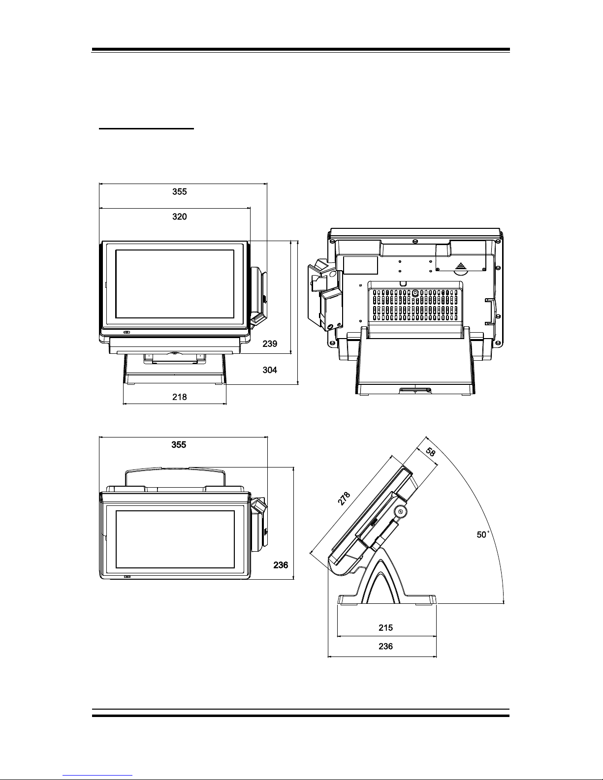
1-2. POS SYSTEM ILLUSTRATION
Small stand type
Front View
Rear View
Top View
Side View
Unit: mm
Page 8
Chapter 1 Introduction
PA-6222 SERIES USERS MANUAL
Page: 4
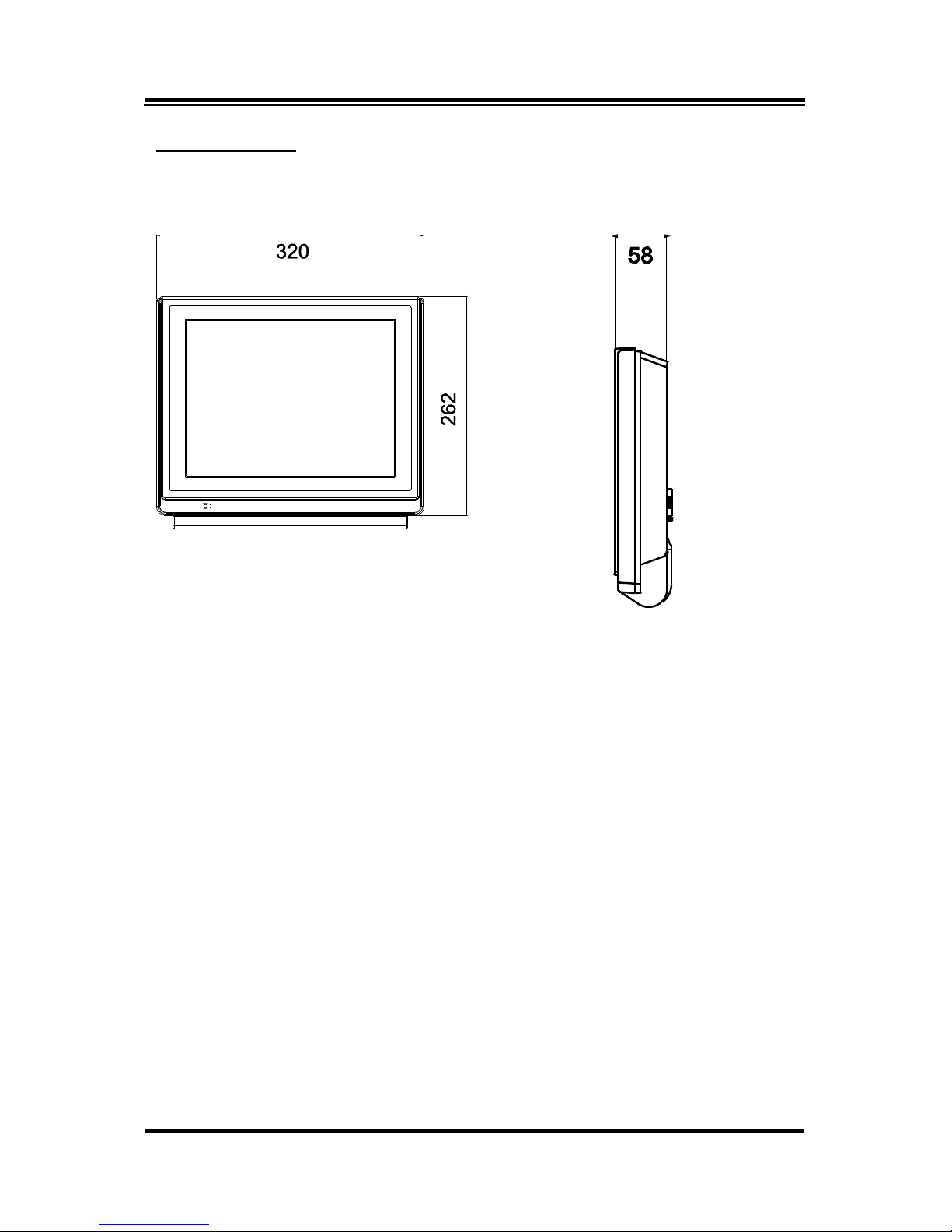
Stand-less type
Front View
Side View
Unit: mm
Page 9
Chapter 1 Introduction
PA-6222 SERIES USERS MANUAL
Page: 5
1-3. SYSTEM SPECIFICATIONS
System
CPU
Intel® Celeron® J1900
Memory
DDR3L SO-DIMM(up to 8GB)
OS Support
Windows POSReady7
Windows 8.1
Windows 10 IoT Enterprise LTSB 2016
LAN
1 x RJ45
VGA
1 x DB-15
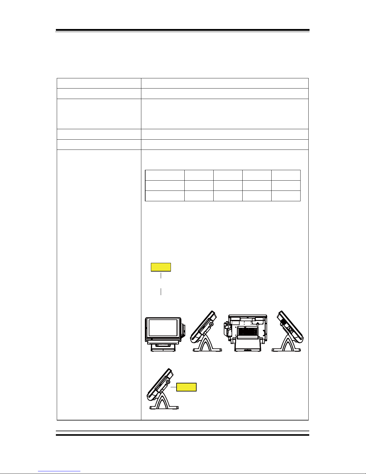
Wireless LAN (Optional)
802.11 b/g/n
AP distance
0˚
90˚
180˚
270˚
5M
-48 dB
-45 dB
-49 dB
-43 dB
10M
-46 dB
-50 dB
-52 dB
-50 dB
Note:
1. Test tolerance: ± 5dB
2. AP: ASUS RT-N56U (2 x internal antenna with 3.8
dBi gain)
Angle: 0° Angle: 270°Angle: 180°Angle: 90°
AP
(Distance)
AP
Page 10

Chapter 1 Introduction
PA-6222 SERIES USERS MANUAL
Page: 6
Audio
2W speaker
System Weight
5kg, PPC only:3.2kg
Dimension (W x H x D)
320 x 303 x 236 mm
Network
10/100/1000M
Mounting Type
Support VESA 75/100
Line Out
1 x phone jack
Cash Drawer
1 x RJ11(+12/24V selectable)
DC-in
1 x 4pin DC Power Jack
Viewing Angel
24~30˚
Serial Ports
3 x RJ45, 1 x RJ45 optional(+5V/12V selectable)
Page 11

Chapter 1 Introduction
PA-6222 SERIES USERS MANUAL
Page: 7
Power Supply: 72 Watt power adapter
Power Consumption
(AC):
System
Status
CPU/
HDD/ Memory
COM & USB Ports to supply
power of Rear I/O
Consumption
OFF
Off
Without
1.6W
IDLE
Turns on, but not to
execute extra AP
14.7W
Full
Loading
100% loading of burn-
in test
18.7W
USB dummy load 500mA x4
29.5W
Certificate: CE/ FCC
Type
Standard
Description
EMI
EN 55022 Class A
-
EMS
EN 55024
-
IEC 61000-4-2
ESD
8kV air discharge
4kV contact discharge
IEC 61000-4-3
RS
80~1000MHz, 3V/m, 80% AM(1kHz)
IEC 61000-4-4
EFT
AC Power Port: 1kV
DC Power Port: 0.5kV
Signal Ports & Telecommunication
Ports: 0.5kV
IEC 61000-4-5
Surge
AC Power Port:
Line to line: 1kV
Line to earth(GND): 2kV
DC Power Port:
Line to earth(GND): 0.5kV
Signal and Telecommunication Port:
Line to GND: 1kV
IEC 61000-4-6
CS
0.15~80MHz, 3Vrms, 80% AM, 1kHz
IEC 61000-4-8
PFMF
50Hz, 1A/m
IEC 61000-4-11
Voltage Dips
> 95% reduction for 0.5 periods
30% reduction for 25 periods
Voltage Interruptions
> 95% reduction for 250 periods
Page 12

Chapter 1 Introduction
PA-6222 SERIES USERS MANUAL
Page: 8
Display
Customer Display
12” TFT LCD
Resolution: 1024 x 768
Touchscreen
Bezel-Free 5-wire resistive touch
Brightness
500 cd/m2 LED Backlight
Environment
Temperature
Operating: 0~35°C (32 ~ 95°F)
Storage: -5~60°C (-4 ~ 140°F)
Humidity
20~90%
Optional accessories
MSR & i-Button
JIS-I or II, ISO Track1+2+3
Fingerprint
8-bit grayscale reader
2nd Display
8” LCD or 10.4” LCD
Customer Display
VFD, 20 columns and 2 lines, each column is 5 x 7 dots
Page 13

Chapter 1 Introduction
PA-6222 SERIES USERS MANUAL
Page: 9
1-4. SAFETY PRECAUTIONS
The following messages are safety reminders on how to protect your systems from
damages, and extending the life cycle of the system.
1. Check the Line Voltage
a. The operating voltage for the power supply should be within the range of
100V to 240V AC; otherwise the system may be damaged.
2. Environmental Conditions
a. Place your PA-6222 on a sturdy, level surface. Be sure to allow enough
space around the system to have easy access needs.
b. Avoid installing your PA-6222 Series POS system in extremely hot or cold
places.
c. Avoid exposure to sunlight for a long period of time (for example, in a
closed car in summer time. Also avoid the system from any heating device.).
Or do not use the PA-6222 when it has been left outdoors in a cold winter
day.
d. Bear in mind that the operating ambient temperature is between 0C and
35C (32F and 95F).
e. Avoid moving the system rapidly from a hot place to a cold place, and vice
versa, because condensation may occur inside the system.
f. Protect your PA-6222 against strong vibrations, which may cause hard disk
failure.
g. Do not place the system too close to any radio-active device. Radio-active
device may cause signal interference.
h. Always shutdown the operation system before turning off the power.
3. Handling
a. Avoid placing heavy objects on the top of the system.
b. Do not turn the system upside down. This may cause the hard drive to
malfunction.
c. Do not allow any objects to fall into this product.
d. If water or other liquid spills into the product, unplug the power cord
immediately.
Page 14

PA-6222 SERIES USER’S MANUAL
Page: 10
SYSTEM
CONFIGURATION
Helpful information that describes the jumper and connector settings,
component locations, and pin assignment.
Sections included:
External I/O Port Pin Assignment
How to Set Jumpers
Component Locations & Jumper Settings
- Mainboard
- VFD Board (peripheral device)
- MSR Board (peripheral device)
Secondary Cash Drawer Port
CHAPTER
2
Page 15
Chapter 2 System Configuration
PA-6222 SERIES USER’S MANUAL
Page: 11
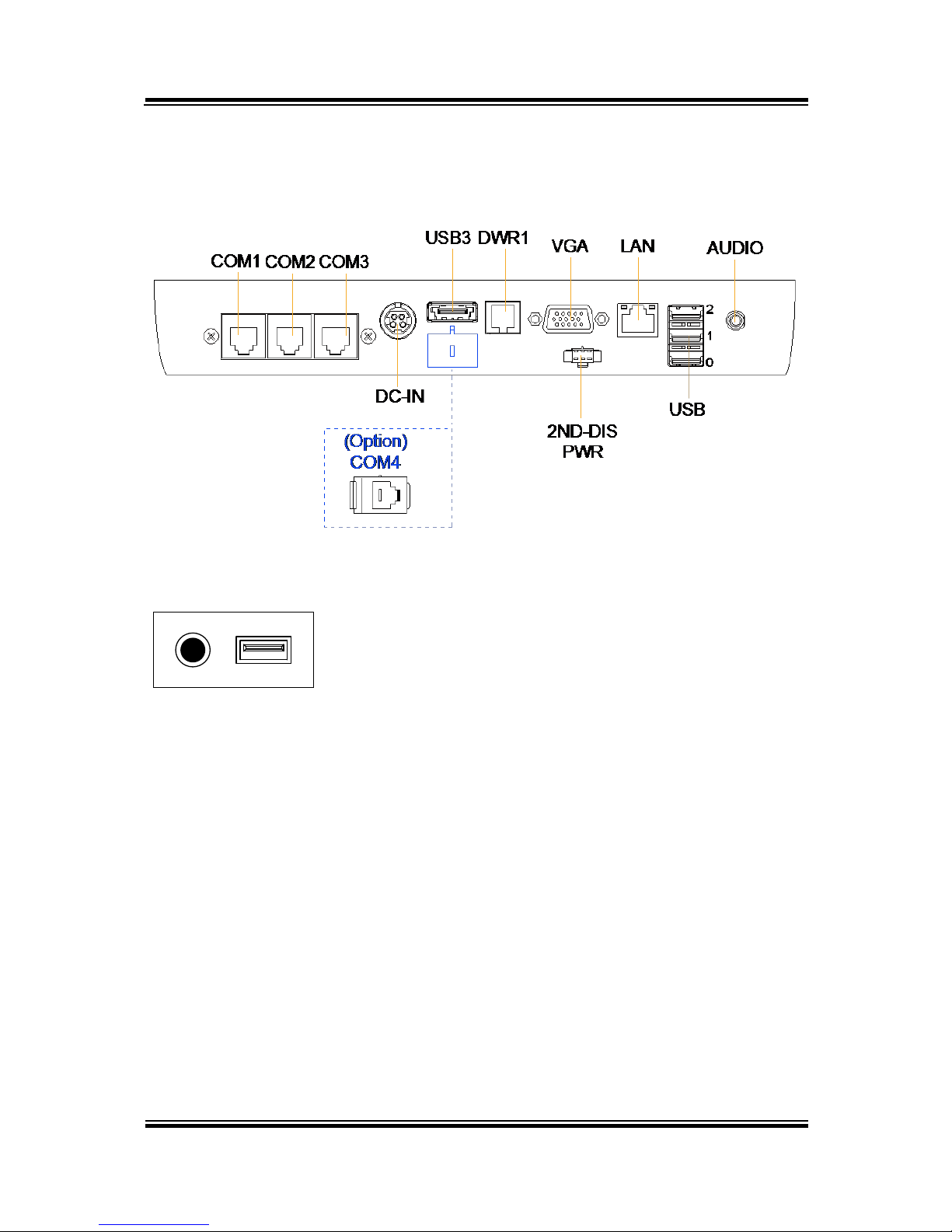
2-1. SYSTEM EXTERNAL I/O PORT & PIN ASSIGNMENT
Rear I/O
Side I/O
Power USB4
button
Page 16
Chapter 2 System Configuration
PA-6222 SERIES USER’S MANUAL
Page:12
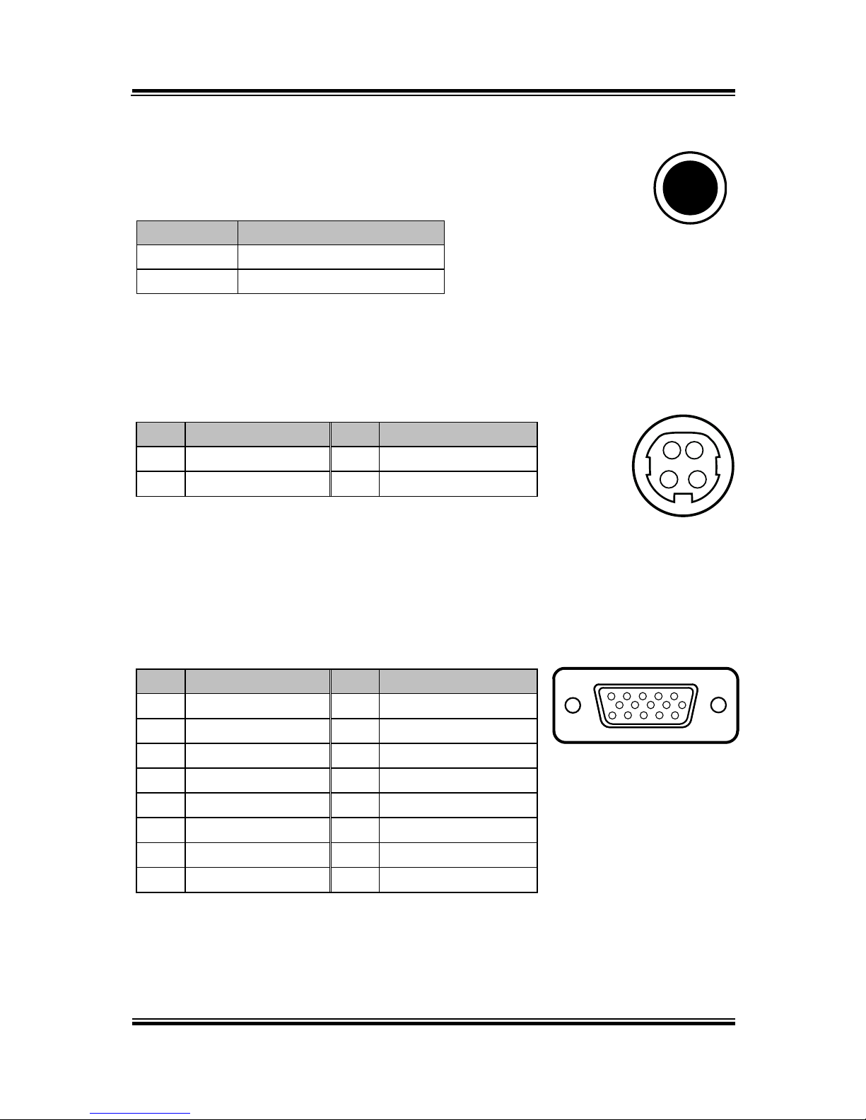
Power Button
To turn on the system, press the power button on the side
of the system briefly.
ACTION
ASSIGNMENT
Click
0V
Release
+3.3V
DC-IN Port
DC-IN: DC Power-In Port (rear IO)
PIN
ASSIGNMENT
PIN
ASSIGNMENT
1
GND
3
+24V
2
GND
4
+24V
VGA Port
VGA: VGA Port, D-Sub 15-pin (rear IO)
PIN
ASSIGNMENT
PIN
ASSIGNMENT
1
RED
9
+5V
2
GREEN
10
GND
3
BLUE
11
NC 4 NC
12
DDCA DATA
5
GND
13
HSYNC
6
GND
14
VSYNC
7
GND
15
DDCA CLK
8
GND
3 4
1 2
DC-IN
Power
Button
15
610
1115
VGA
Page 17
Chapter 2 System Configuration
PA-6222 SERIES USER’S MANUAL
Page: 13
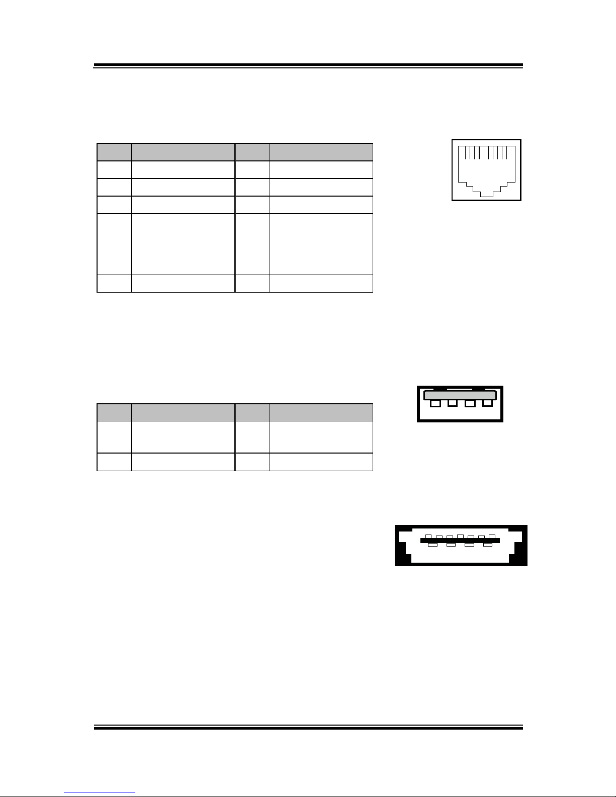
COM Port
COM1, COM2, COM3: COM Ports (rear IO)
PIN
ASSIGNMENT
PIN
ASSIGNMENT
1
DCD1/2/3
6
DSR1/2/3
2
RXD1/2/3
7
RTS1/2/3
3
TXD1/2/3
8
CTS1/2/3
4
DTR1/2/3
9
RI/+5V/+12V
selectable
(Maximum
current: 1A)
5
GND
10
NC
USB Port
USB0, USB1, USB2, USB3, USB4: USB Port Type A Ports
USB0~3: Real I/O
USB4: Side IO
PIN
ASSIGNMENT
PIN
ASSIGNMENT
1
+5V(Maximum
current: 0.5A)
3
D+
2
D- 4 GND
101
COM1/
COM2/
COM3
1 4
USB0/
USB1/
USB2/
USB4/
1 4
USB3
Page 18
Chapter 2 System Configuration
PA-6222 SERIES USER’S MANUAL
Page:14
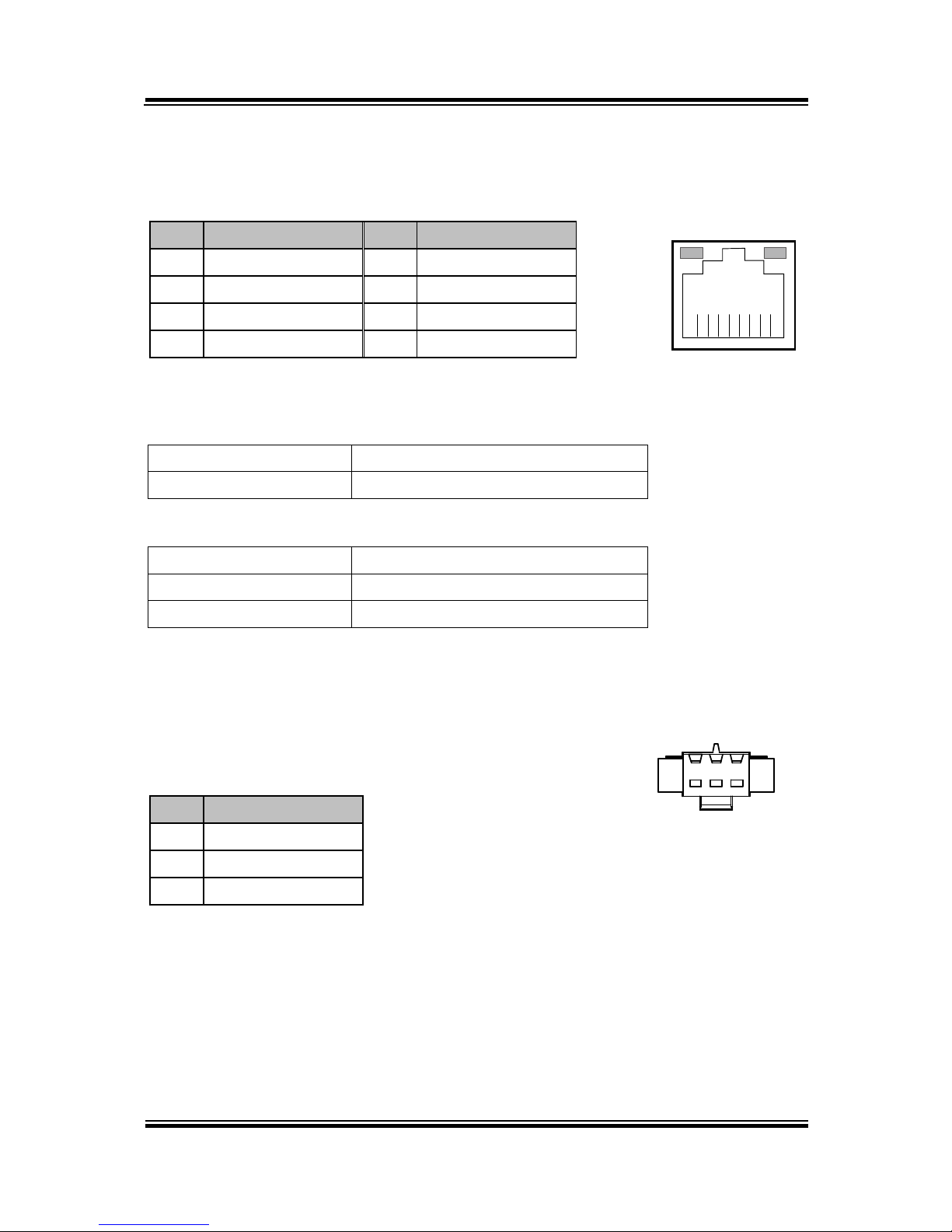
LAN Port
LAN: LAN RJ45 Port (rear IO)
PIN
ASSIGNMENT
PIN
ASSIGNMENT
1
MDI_0P
5
MDI_2N
2
MDI_0N
6
MDI_1N
3
MDI_1P
7
MDI_3P
4
MDI_2P
8
MDI_3N
LAN LED Indicator:
Left Side LED
Yellow Color Blinking
LAN Message Active
Off
No LAN Message Active
Right Side LED
Green Color On
10/100Mbps LAN Speed Indicator
Orange Color on
Giga LAN Speed Indicator
Off
No LAN switch/ hub connected.
2nd Display Power Port (Optional)
2nd DIS PWR: DV12 Power Supply of 2nd Display
PIN
ASSIGNMENT
1
VCC12
2
GND
3
VCC12
Yellow Green
8 1
LAN
1 3
2ND DIS PWR
Page 19

Chapter 2 System Configuration
PA-6222 SERIES USER’S MANUAL
Page: 15
DC 24V Port (Optional)
DC 24V Port: DC24V power supply for the stand-printer
PIN
ASSIGNMENT
P1
GNDV
P2
+24V
P3
NA
Cash Drawer Port
DRW1, DRW1-1, DRW1-2: Signal from M/B GPIO (rear I/O)
PIN
ASSIGNMENT
PIN
ASSIGNMENT
1
GND
4
+12V/+24V (Max. current: 1A)
2
Drawer Open
5
NC 3 Drawer Sense
6
GND
DRW1
Open
Close
PB-6822RA, RB
Write
To
Write
To
700h
588h
000h
588h
PB-6822RC
Write
To
Write
To
02h
SIO LDN
06h’s 90h
00h
SIO LDN
06h’s 90h
16
DRW1
DC 24V Port
Page 20
Chapter 2 System Configuration
PA-6222 SERIES USER’S MANUAL
Page:16
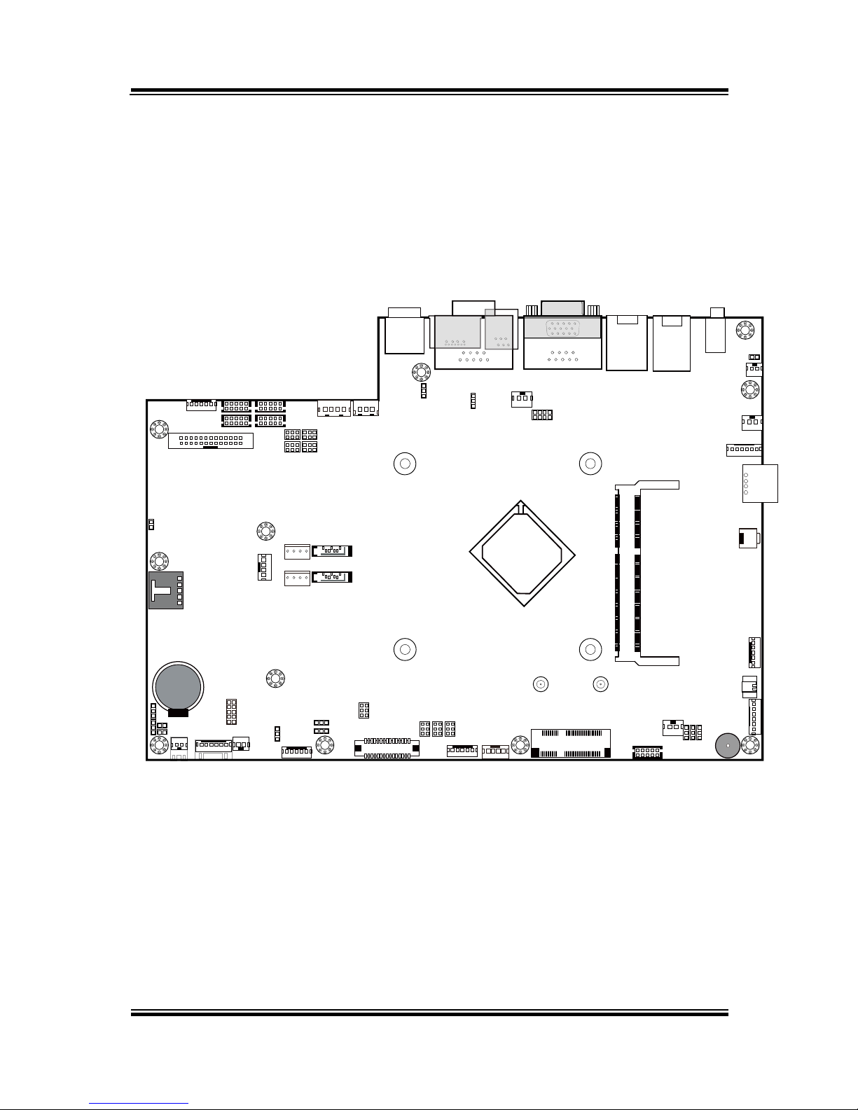
2-2. MAINBOARD COMPONENT LOCATIONS & JUMPER
SETTINGS
M/B: PB-6822
SW1_2
SPK2
PS/2_1
1
5
TOUCH1
LED1_1
LED1_3
1
LVDS1
USB7
J3
JP_VDD1
JP_12
JP_8
JP_9
USB1
JP32
SW1_3
JP19
JP30
USB2
COM1_1
COM4_1
COM2_1
COM3_1
JP_COM4
JP_COM3
JP_COM2
JP_COM1
PRT_PWR1
PWR_IN1
VGA1
USB8LAN1
LINE-OUT1
JP31
USB4
SW1
USB6
JI_BUTTON1
PS/2_2
SP1
SPK1
SLOT1
COM4_2
JP20
JP21
JP22
COM2
COM3
DC5V_PWR1
JP37
JP29
JP5
DC12V_PWR1
LPT1
J2
SATA2
SATA1
JPWR_4P2
JPWR_4P1
JP14
JP15
JINV4
JINV1
JP4
JP3
JP38JP39
30
291
2
Battery
1
1
1
1
1 31 4
1
6
5
10
14
1
1
1
1
1 21 21 2
5 65 65 6
526
1
1
1
1
1
12
910
6
1
1
6
1
1
15
15
1
5
11517 51
21618
52
1
4
1
127
8
1
10
5
6
1
6
1
1
1
2
255
6
5
6
6
1
1
4
1
2
6
10
5
10
5
26
13
14
1
1 4
1 4
1 7
1 7
Intel
®
Celeron® J1900
Quad-Core
DIMM1
1
2
71
72
73
74
203
204
ESATA1
DRW1
15
1
61
1
PB-6822 Mainboard Component Locations
Page 21
Chapter 2 System Configuration
PA-6222 SERIES USER’S MANUAL
Page: 17
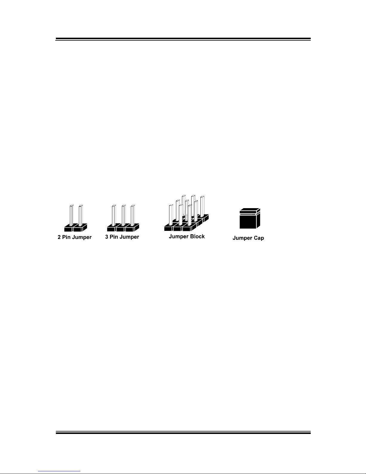
2-2-1. How to Set Jumpers
You can configure your board by setting the jumpers. A jumper consists of two or three
metal pins with a plastic base mounted on the card, and by using a small plastic "cap",
also known as the jumper cap (with a metal contact inside), you are able to connect the
pins. So you can set-up your hardware configuration by "opening" or "closing" pins.
Jumpers can be combined into sets that called jumper blocks. When jumpers are all in
the block, you have to put them together to set up the hardware configuration. The
figure below shows what this looks like.
Jumpers & caps
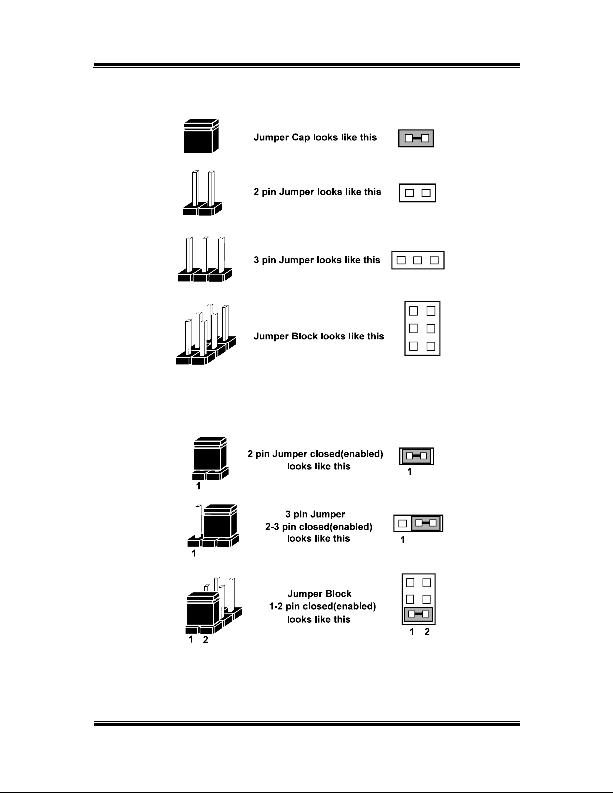
If a jumper has three pins for example, labelled PIN1, PIN2, and PIN3. You can
connect PIN1 & PIN2 to create one setting and shorting. You can either connect PIN2
& PIN3 to create another setting. The same jumper diagrams are applied all through
this manual. The figure below shows what the manual diagrams look and what they
represent.
Page 22
Chapter 2 System Configuration
PA-6222 SERIES USER’S MANUAL
Page:18
Jumper diagrams
Jumper settings
Page 23
Chapter 2 System Configuration
PA-6222 SERIES USER’S MANUAL
Page: 19
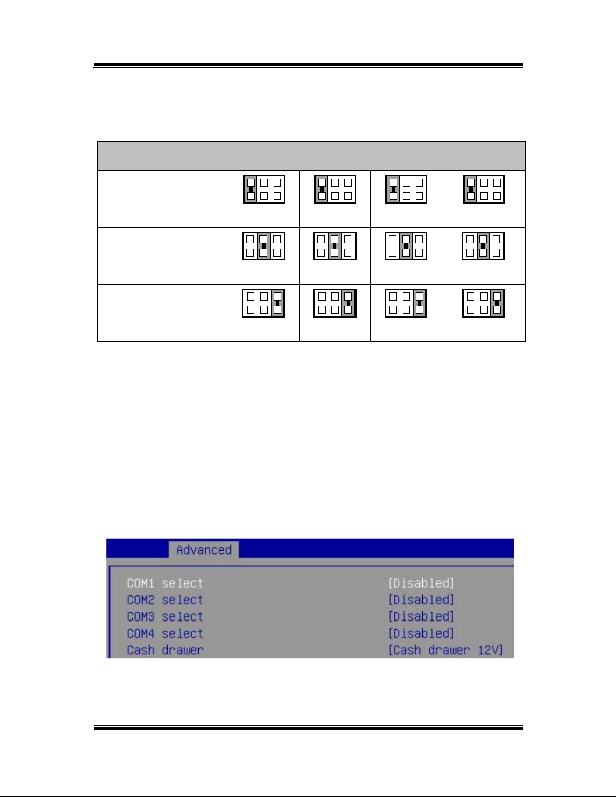
COM Port RI & Voltage Selection
JP_COM1, JP_COM2, JP_COM3, JP_COM4: Pin-headers on board
SELECTION
JUMPER
SETTING
JUMPER ILLUSTRATION
RI
1-2
5
6
1
2
JP_COM1
5
6
1
2
JP_COM2
5
6
1
2
JP_COM3
5
6
1
2
JP_COM4
+12V
3-4
5
6
1
2
JP_COM1
5
6
1
2
JP_COM2
5
6
1
2
JP_COM3
5
6
1
2
JP_ COM4
+5V
5-6
5
6
1
2
JP_COM1
5
6
1
2
JP_COM2
5
6
1
2
JP_COM3
5
6
1
2
JP_ COM4
Note: Manufacturing Default is no connection for JP_COM1, JP_COM2, JP_COM3 and
JP_COM4.
Caution:
1. Voltage of external COM 1~ COM4 ports are made to control on BIOS for your convenience.
The corresponding jumpers JP_COM1~ JP_COM4 are set open (no connection) by default;
refer to Voltage Adjust Configuration for detailed jumper setting (BIOS default at RI).
2. JP_COM1~ JP_COM4 are enabled when COM1~ COM4 voltage adjustment is disabled on
BIOS
3. Voltage of COM port is adjustable by BIOS or jumpers. Either way cannot be applied
simultaneously in case of system error, component damage or serious boot failure.
PS: COM4 is optional
Page 24
Chapter 2 System Configuration
PA-6222 SERIES USER’S MANUAL
Page:20
COM Connector
COM1-1, COM2-1, COM3-1, COM4-1, COM4-2: COM Connectors
PIN
ASSIGNMENT
PIN
ASSIGNMENT
1
DCD
6
DSR
2
RXD
7
RTS
3
TXD
8
CTS
4
DTR
9
RI/+5V/+12V selectable
(Max. current: 1A)
5
GND
10
NC
For details, refer to COM Port RI & Voltage Selection.
I-Button Connector
JI_BUTTON1: i-Button Connector
PIN
ASSIGNMENT
1
COM3_DTR_R_I
2
COM3_RXD_R_I
I-Button Function Selection
JP20, JP21, JP22: i-Button Function Connectors
SELECTION
JUMPER SETTING
JUMPER ILLUSTRATION
COM 3
1-2
1
3
JP20/JP21/JP22/
i-Button*
2-3
1
3
JP20/JP21/JP22/
Note: Manufacturing Default is COM3.
*COM3 & COM3-1 will not function when jumpers JP20, JP21 & JP22 are set as “i-Button.”
1
2
JI_BUTTON1
51
10
6
COM1-1/
COM2-1/
COM3-1/
COM4-1/
610
1
5
COM4-2/
Page 25
Chapter 2 System Configuration
PA-6222 SERIES USER’S MANUAL
Page: 21
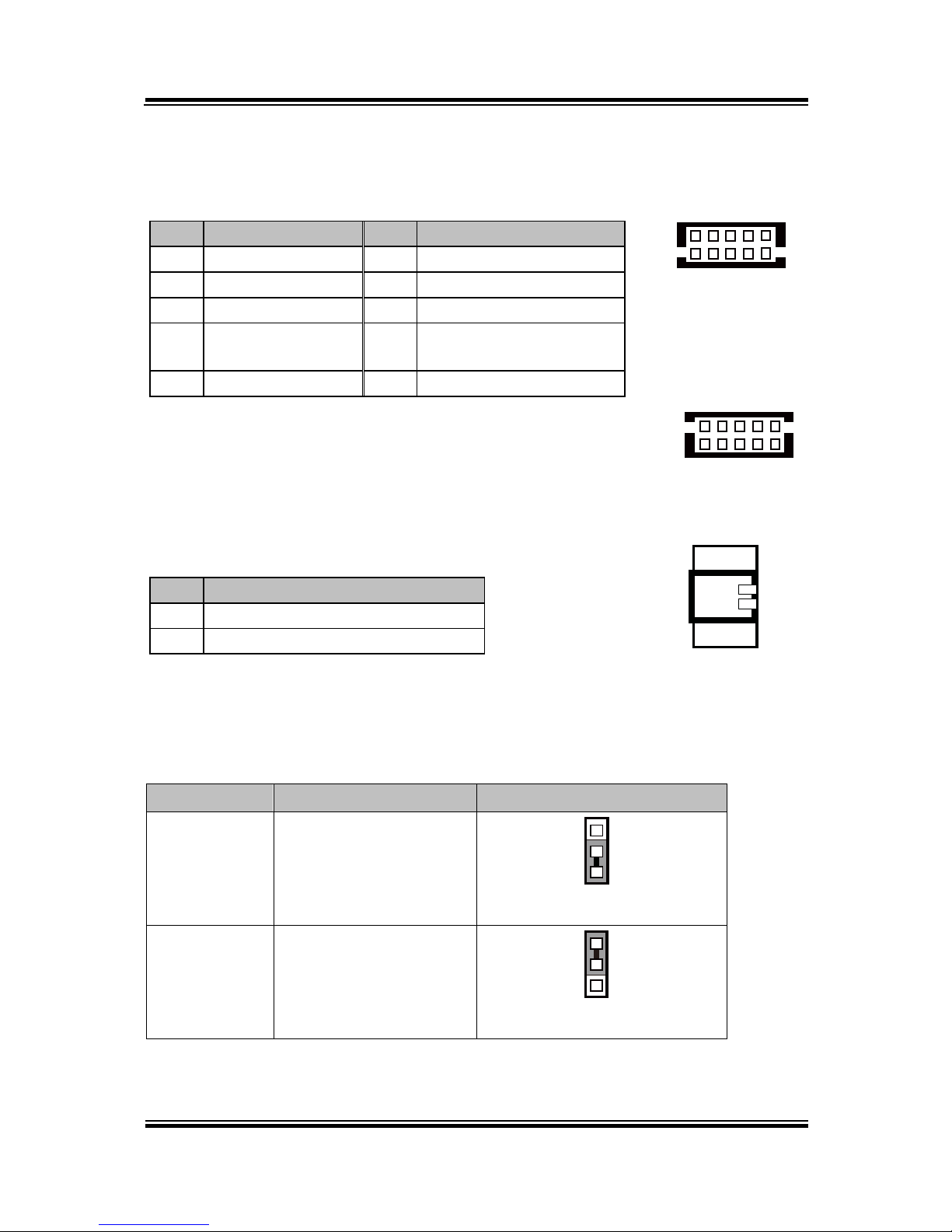
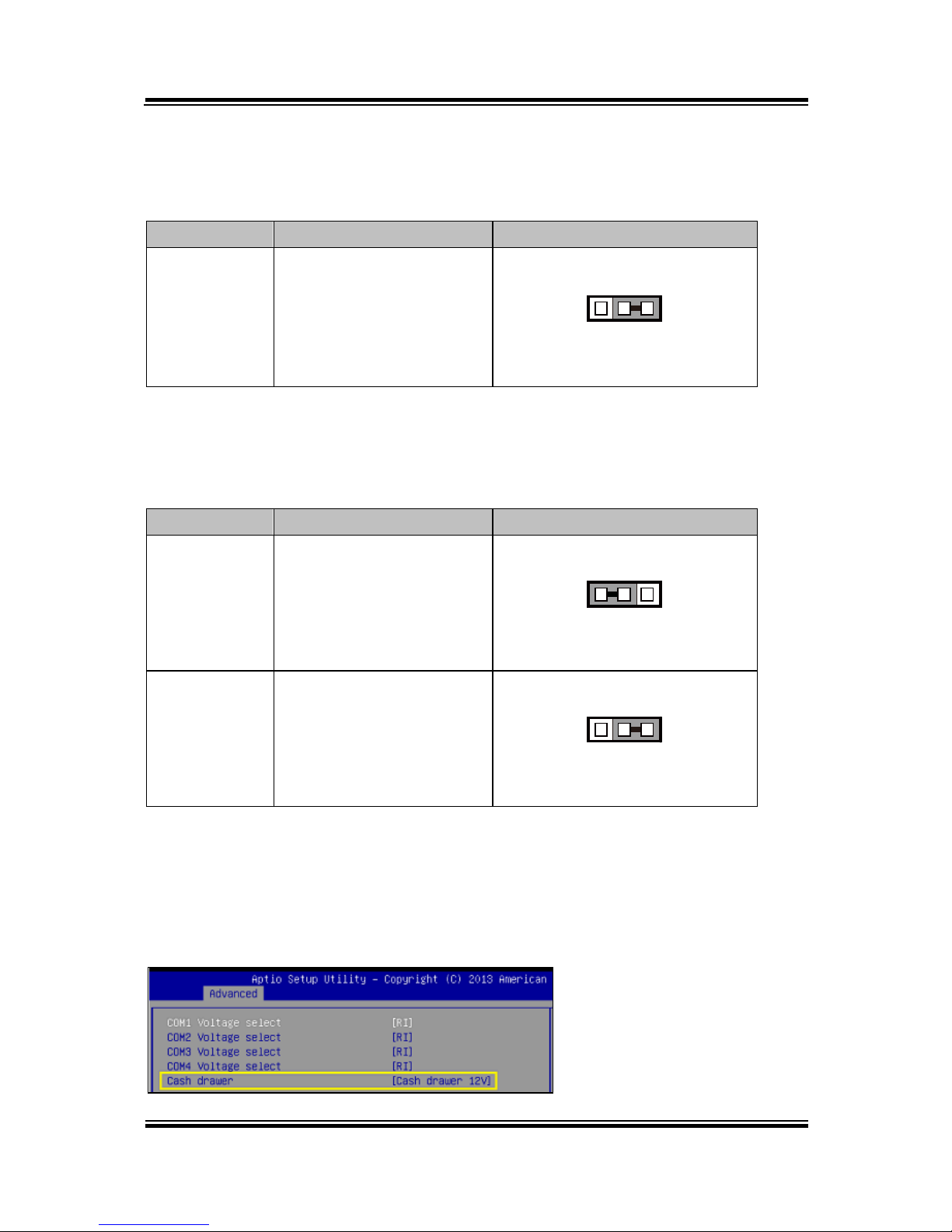
Cash Drawer Control Selection
JP37: DRW1 control connector
SELECTION
JUMPER SETTING
JUMPER ILLUSTRATION
DRW1
2-3
1 3
JP37
Cash Drawer Power Selection
JP29: DRW1 power selection
SELECTION
JUMPER SETTING
JUMPER ILLUSTRATION
+24V
1-2
1 3
JP29
+12V
2-3
1 3
JP29
Caution:
1. Voltage of external DRW1 port is made to control on BIOS for your convenience. The
corresponding jumper JP29 is set open (no connection) by default.
2. JP29 is enabled when Cash drawer is disabled on BIOS.
3. Voltage of cash drawer port is adjustable by BIOS or jumpers. Either way cannot be applied
simultaneously in case of system error, component damage or serious boot failure.
Page 26
Chapter 2 System Configuration
PA-6222 SERIES USER’S MANUAL
Page:22
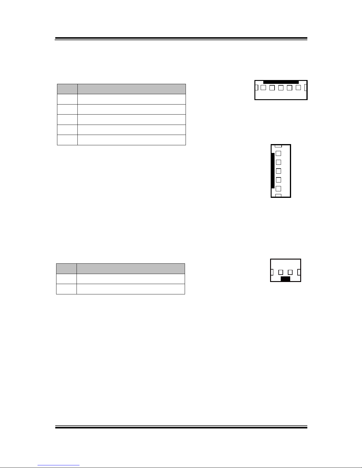
USB Connector
USB1, USB2, USB6, USB7: USB 2.0 connector
PIN
ASSIGNMENT
1
5V (Maximum current: 0.5A)
2
D- 3 D+ 4 GND
5
GND
Note: USB1 would be used when jumpers
JP14 & JP15 are set as 1-2 (short)
connected.
LED Connector
LED1_1, LED1_3: Power indication LED connector
PIN
ASSIGNMENT
1
GND
2
PWR_LED
2 1
LED1_1/
LED1_3/
1
5
USB1/
USB2/
USB7/
1
5
USB6
Page 27
Chapter 2 System Configuration
PA-6222 SERIES USER’S MANUAL
Page: 23
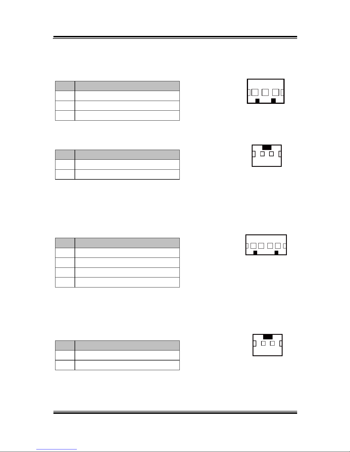
Power Connector
DC12V_PWR1: DC 12Voltage Provider Connector
PIN
ASSIGNMENT
1
VCC12
2
GND
3
VCC12
DC5V_PWR1: DC 5Voltage Provider Connector
PIN
ASSIGNMENT
1
5V 2 GND
Power for Thermal Printer Connector
PRT_PWR1: Power for Thermal Printer Connector
PIN
ASSIGNMENT
1
VCC24SB
2
VCC24SB
3
GND
4
GND
External Speaker Connector
SPK1, SPK2: External speaker connector
PIN
ASSIGNMENT
1
SPK_GND
2
SPK_OUT
1 3
DC12V_PWR1
1 4
PRT_PWR1
12
SPK1/
SPK2/
12
DC5V_PWR1
Page 28
Chapter 2 System Configuration
PA-6222 SERIES USER’S MANUAL
Page:24
Inverter Connector
JINV1, JINV4: Inverter connectors
PIN
ASSIGNMENT
1
+12V
2
+12V
3
GND
4
BRCTR
5
GND
6
LVDS_BKLTEN
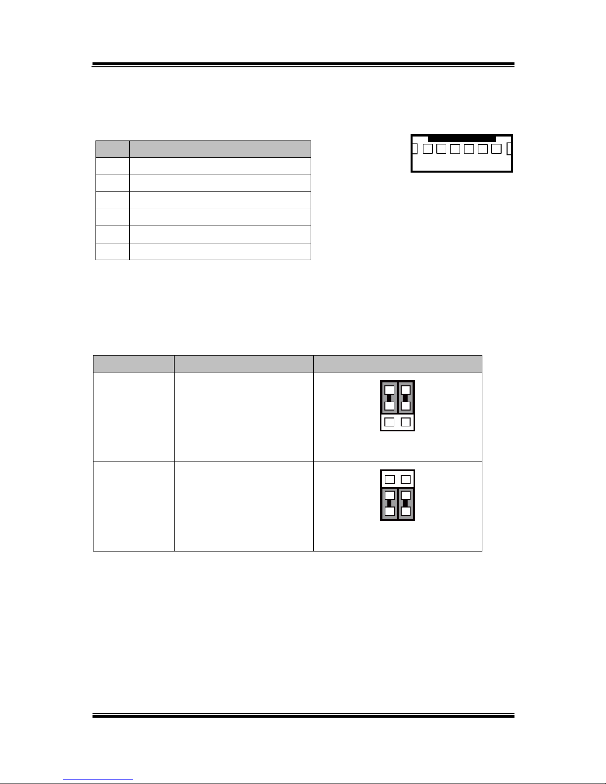
LED Backlight Power Control Selection
JP12: LED backlight power control connectors
SELECTION
JUMPER SETTING
JUMPER ILLUSTRATION
Control by
driver on M/B
1-3, 2-3
It applied to the panel
without driver built-in
21
65
JP12
Control by
PWM
3-5, 4-6
It applied to the panel
with built-in driver inside
21
65
JP12
Note: Manufacturing Default is Control by PWM.
1
6
JINV1/
JINV4/
Page 29

Chapter 2 System Configuration
PA-6222 SERIES USER’S MANUAL
Page: 25
Panel Resolution Selection
JP8, JP9: Panel resolution control connectors
SELECTION
JUMPER
SETTING
JUMPER ILLUSTRATION
1024 x 768
(24 bit)
JP8: 1-3, 4-6
JP9: 3-5, 4-6
21
65
JP8
21
65
JP9
Note: Manufacturing Default is 1024 x 768 (24bit).
LVDS Connector
LVDS1: LVDS Connector
PIN
ASSIGNMENT
PIN
ASSIGNMENT
1
LVDS_VCC
16
LVDS_CLKA_D+
2
GND
17
VDS_CLKA_D-
3
NC
18
GND
4
NC
19
LVDS_A2_D+
5
GND
20
LVDS_A2_D-
6
LVDS_B2_D-
21
GND
7
LVDS_B2_D+
22
LVDS_A1_D+
8
GND
23
LVDS_A1_D-
9
LVDS_B1_D-
24
GND
10
LVDS_B1_D+
25
LVDS_A0_D+
11
LVDS_B3_D+
26
LVDS_A0_D-
12
LVDS_B3_D-
27
LVDS_A3_D+
13
LVDS_B0_D+
28
LVDS_A3_D-
14
LVDS_B0_D-
29
LVDS_VCC
15
GND
30
LVDS_VCC
2
1 29
30
LVDS1
Page 30
Chapter 2 System Configuration
PA-6222 SERIES USER’S MANUAL
Page:26
Touch Panel Connector
TOUCH1: Touch panel connectors
PIN
ASSIGNMENT
PIN
ASSIGNMENT
1
LR (Low Right)
4
UR (Up Right)
2
LL (Low Left)
5
UL (Up Left)
3
Probe
Touch Panel Signal Interface Selection
JP14, JP15, JP38, JP39: Control connectors for touch panel signal interface
SELECTION
JUMPER
SETTING
JUMPER ILLUSTRATION
USB1
Connector
JP14: 1-2
JP15: 1-2
JP38: 2-3
JP39: 2-3
1 3
JP14
1 3
JP15
3
1
JP38
3
1
JP39
USB
Interface
JP14: 2-3
JP15: 2-3
JP38: 2-3
JP39: 2-3
1 3
JP14
1 3
JP15
3
1
JP38
3
1
JP39
RS-232
Interface
JP14: 1-2
JP15: 1-2
JP38: 1-2
JP39: 1-2
1 3
JP14
1 3
JP15
3
1
JP38
3
1
JP39
Note: 1. Manufacturing Default is USB Interface.
2. The COM2 & COM2-1 connector will not function when JP38 & JP39 are set
as 1-2 connected.
3. USB1 connector when JP14 & JP15 are set as 1-2 connected.
1
5
TOUCH1
Page 31

Chapter 2 System Configuration
PA-6222 SERIES USER’S MANUAL
Page: 27
Clear CMOS Data Selection
JP3: Clear CMOS data selection
SELECTION
JUMPER SETTING
JUMPER ILLUSTRATION
Normal
Open
1
JP3
Clear CMOS*
1-2
1
JP3
Note: Manufacturing Default is Normal.
*To clear CMOS data, you must power-off the computer and set the jumper to “Clear CMOS” as
illustrated above. After five to six seconds, set the jumper back to “Normal” and power-on the
computer.
MSR/Card Reader Connector
PS/2_1, PS/2_2: MSR/Card reader connectors
PIN
ASSIGNMENT
1
KB_CLK (Output)
2
KB_CLK_C (Input)
3
KB_DATA_C (Input)
4
KB_DATA (Output)
5
+5V
6
GND
6
1
PS/2_1
6
1
PS/2_2
Page 32

Chapter 2 System Configuration
PA-6222 SERIES USER’S MANUAL
Page:28
SATA & SATA Power Connector
SATA1, SATA2: Serial ATA connectors
PIN
ASSIGNMENT
PIN
ASSIGNMENT
1
G1 5 RX-
2
TX+
6
RX+
3
TX-
7
G3 4 G2
Note: SATA1 only supports the optional RAID
function on board.
JPWR_4P1, JPWR_4P2: Serial ATA power connectors
PIN
ASSIGNMENT
1
VCC
2
GND
3
GND
4
VCC12
Note: JPWR_4P1 only supports the
optional RAID function on board.
1 7
SATA1/
SATA2/
1 4
JPWR_4P1/
JPWR_4P2/
Page 33

Chapter 2 System Configuration
PA-6222 SERIES USER’S MANUAL
Page: 29
Printer Connector
LPT1: Printer connector
PIN
ASSIGNMENT
PIN
ASSIGNMENT
1
STBJ
14
ALFJ
2
PDR0
15
ERRJ
3
PDR1
16
PAR_INITJ
4
PDR2
17
SLCTINJ
5
PDR3
18
GND
6
PDR4
19
GND
7
PDR5
20
GND
8
PDR6
21
GND
9
PDR7
22
GND
10
ACKJ
23
GND
11
BUSY
24
GND
12
PE
25
GND
13
SLCTJ
26
NC
26
13
14
1
LPT1
Page 34

Chapter 2 System Configuration
PA-6222 SERIES USER’S MANUAL
Page:30
Mini-PCIe / mSATA Connector
SLOT1: Mini-PCIe connector, not support USB function
PIN
ASSIGNMENT
PIN
ASSIGNMENT
1
WAKE#
27
GND
2
+3.3V
28
+1.5V
3
Reserved
29
GND
4
GND
30
SMB_CLK
5
Reserved
31
PETn2
6
+1.5V
32
SMB_DATA
7
CLKREQ#
33
PETp2
8
Reserved
34
GND
9
GND
35
GND
10
Reserved
36
NC
11
REFCLK1-
37
GND
12
Reserved
38
NC
13
REFCLK1+
39
+3.3V
14
Reserved
40
GND
15
GND
41
+3.3V
16
Reserved
42
Reserved
17
Reserved
43
GND
18
GND
44
Reserved
19
Reserved
45
NC
20
Reserved
46
Reserved
21
GND
47
NC
22
PERST#
48
+1.5V
23
PERn2
49
NC
24
+3.3SB
50
GND
25
PERp2
51
Reserved
26
GND
52
+3.3V
12151617
18
51
52
SLOT1
Page 35

Chapter 2 System Configuration
PA-6222 SERIES USER’S MANUAL
Page: 31
2-3. VFD BOARD COMPONENT LOCATIONS & PIN
ASSIGNMENT
VFD Board: MB-4103, LD720
JP12V
CN1
1
1
16
MB-4103 & LD720 VFD Board Component Locations
Page 36

Chapter 2 System Configuration
PA-6222 SERIES USER’S MANUAL
Page:32
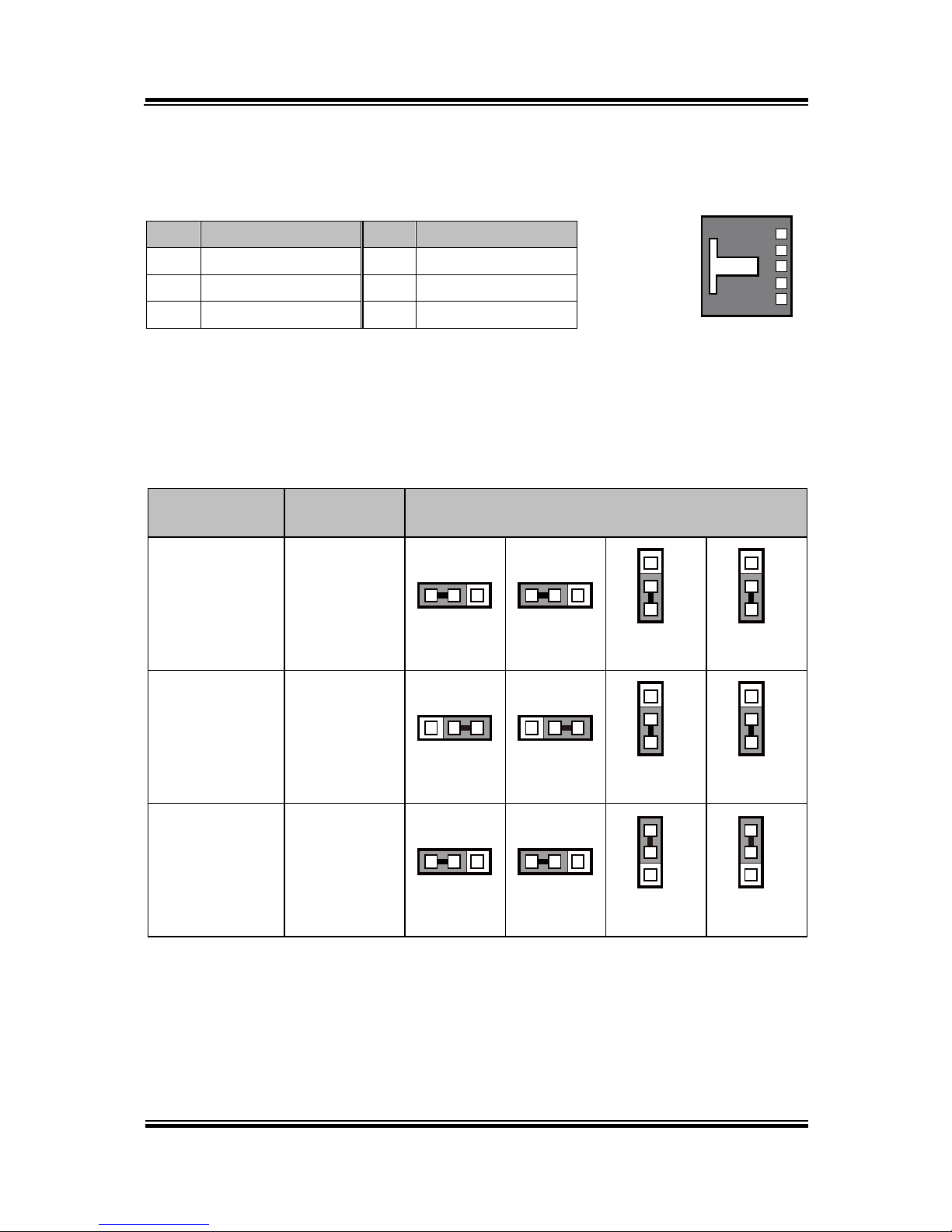
Power Switch Selection
JP12V: Power Switch Selection
SELECTION
JUMPER SETTING
JUMPER ILLUSTRATION
OFF
1-2
3
1
JP12V
ON
2-3
3
1
JP12V
Note: Manufacturing Default is ON.
RS-232 Serial Interface Connector
CN1: RS-232 serial interface wafer
PIN
ASSIGNMENT
PIN
ASSIGNMENT
1
GND
9
NC 2 TXD
10
NC 3 RXD
11
NC 4 DTR
12
NC 5 DSR
13
NC 6 RTS
14
NC 7 CTS
15
NC 8 +12V/+5V
16
NC
1
16
CN1
Page 37

Chapter 2 System Configuration
PA-6222 SERIES USER’S MANUAL
Page: 33
2-4. MSR BOARD COMPONENT LOCATIONS & PIN
ASSIGNMENT
ID TECH
1
7
CN
ID-TECH MSR Board Component Locations
Main Connector
CN:
PIN
ASSIGNMENT
PIN
ASSIGNMENT
1
Chassis Ground
5
K-CLK
(Computer connections)
2
P-CLK
(Keyboard connections)
6
K-DATA
(Computer connections)
3
P-DATA
(Keyboard connections)
7
GND
4
+5V Vcc
1
7
CN
Page 38

Chapter 2 System Configuration
PA-6222 SERIES USER’S MANUAL
Page:34
MB-3012
IO1
I_BUTTON1
1 12
1
2
MB-3012 MSR Board Component Locations
Information Button Reader
I_BUTTON1: Information button reader
PIN
ASSIGNMENT
1
I_B1
2
GND
Output Connector
IO1: Output wafer
PIN
ASSIGNMENT
PIN
ASSIGNMENT
1
CLK_KB
7
RX_MSR
2
CLK_PC
8
TX_MSR
3
DATA_KB
9
GND
4
DATA_PC
10
USB_D+_R
5
+5V
11
USB_D-_R
6
CHASSIS GND
12
GND
1
2
I_BUTTON1
1 12
IO1
Page 39

Chapter 2 System Configuration
PA-6222 SERIES USER’S MANUAL
Page: 35
2-5. Secondary Cash Drawer
2-5-1. DRW1-2 Port (Only for PA-6222RC)
DRW1 is used by default. If you need a second port, adopt either way below.
Step.1
DRW1 includes two groups of
GPIO pins. The second group
is normally unused but can be
enabled by the jumper.
Set the pin-header jumper
JP37 as 1-2 connected if
necessary.
JP37: DRW1-2 control
connector
Note: Manufacturing Default is GND.
SELECTIO
N
JUMPER SETTING
JUMPER ILLUSTRATION
DRW1-2
Open
1-2
GND
2-3
Page 40

Chapter 2 System Configuration
PA-6222 SERIES USER’S MANUAL
Page:36
Step.2
You can split DRW1 into two channels of DRW1-1 & DRW1-2 with the Y-Cable
(optional unit).
Step.3
DRW1, DRW1-1, DRW1-2 shares the same power source
(refer to Cash Drawer Power Selection for adjustment, default at 12V).
DRW1, DRW1-1, DRW1-2: Signal from M/B GPIO (rear I/O)
DRW1-1
Open
Close
PB-6822RA, RB
Write
To
Write
To
700h
588h
000h
588h
PB-6822RC
Write
To
Write
To
02h
SIO LDN06h’s 90h
00h
SIO LDN 06h’s 90h
DRW1-2
OPEN
CLOSE
PB-6822RA, RB
Write
To
Write
To
N/A
N/A
N/A
N/A
PB-6822RC
Write
To
Write
To
04h
SIO LDN 06h’s 90h
00h
SIO LDN 06h’s 90h
PIN
ASSIGNMENT
PIN
ASSIGNMENT
1
GND
4
+12V/+24V (Max. Current: 1A)
2
Drawer Open
5
NC
3
Drawer Sense
6
GND
Page 41

PA-6222 SERIES USERS MANUAL
Page:37
SOFTWARE
This chapter provides the detailed information of driver utilities and
BIOS settings for the system.
Sections included:
Driver
- Intel
®
Chipset Device Software Installation Utility
- VGA Driver Utility
- LAN Driver Utility
- Sound Driver Utility
- Touchsreen Driver Utility
- For Intel Trusted Execution Engine Interface
Embedded Peripheral Device
- VFD
- MSR
API
BIOS Operation
- Setup
- Watchdog Timer Configuration
- Update Procedure
- System Resource Map
CHAPTER
3
Page 42

Chapter 3 Software
PA-6222 SERIES USERS MANUAL
Page:38
3-1. DRIVER
3-1-1. Introduction
Enclosed with the PA-6222 Series package is our driver utilities, which comes in a
DVD-ROM format.
3-1-1-1 . API Package Folder
Refer to the "3-3 API" for the details.
+--->\DEMO PROJECT\
+--->\ProxAPI standard\
+--->\Document\
3-1-1-2 . Driver Folder
1. The sequence of setup is "Main Chip -> VGA -> LAN -> SOUND -> TXE ->
TOUCH[Device folder]"
2. You will be prompted to reboot when installation is complete.
+--->\Flash BIOS\AFUa.bat
+--->\Plaform\
+--->\Device\
3-1-1-3 . User Manual Folder
\AdbeRdr930_en_US.exe (PDF File reader)
3-1-1-4 . README
The DRIVER DISC introduction
Page 43

Chapter 3 Software
PA-6222 SERIES USERS MANUAL
Page:39
3-1-2. Intel
®
Chipset Device Software Installation Utility
3-1-2-1. Introduction
The Intel® Chipset Software Installation Utility installs Windows *.INF files to the
target system. These files outline to the operating system how to configure the Intel
chipset components in order to ensure the following features function properly:
SATA Storage Support (SATA & SATA II)
USB Support (1.1 & 2.0)
Identification of Intel
®
Chipset Components in Device Manager
3-1-2-2. Installation of Intel® Chipset Driver
The utility pack is to be installed only for POSReady 7, Windows 8.1 and Windows
10 series, and it should be installed right after the OS installation. Please follow the
steps below:
1. Connect the USB CD-ROM device to PA-6222 and insert the driver disk.
2. Enter the “Main Chip” folder where the Chipset driver is located (depending
on your OS platform).
3. Click Setup.exe file for driver installation.
4. Follow the on-screen instructions to complete the installation.
5. Once the installation is completed, shut down the system and restart PA-6222
for the changes to take effect.
Page 44

Chapter 3 Software
PA-6222 SERIES USERS MANUAL
Page:40
3-1-3. VGA Driver Utility
The VGA interface embedded with PA-6222 can support a wide range of display
types. You can have dual displays via CRT & LVDS interfaces work
simultaneously.
3-1-3-1. Installation of VGA Driver
To install the Graphics driver, follow the steps below:
1. Connect the USB-CD ROM device to PA-6222 and insert the driver disk.
2. Enter the “Graphics” folder where the VGA driver is located (depending on
your OS platform).
3. Click Setup.exe file for driver installation.
4. Follow the on-screen instructions to complete the installation.
5. Once the installation is completed, shut down the system and restart PA-6222
for the changes to take effect.
3-1-4. LAN Driver Utility
PA-6222 is enhanced with LAN function that can support various network adapters.
Installation platform for the LAN driver is listed as follows:
3-1-4-1. Installation of LAN Driver
To install the LAN Driver, follow the steps below:
1. Connect the USB DVD-ROM device to PA-6222 and insert the driver disk.
2. Enter the “LAN Chip” folder where the LAN driver is located (depending on
your OS platform).
3. Click Setup.exe file for driver installation.
4. Follow the on-screen instructions to complete the installation.
5. Once the installation is completed, shut down the system and restart PA-6222 for
the changes to take effect.
For more details on the Installation procedure, please refer to the Readme.txt
file found on LAN Driver Utility.
Page 45

Chapter 3 Software
PA-6222 SERIES USERS MANUAL
Page:41
3-1-5. Sound Driver Utility
The sound function enhanced in this system is fully compatible with Windows
POSReady 7 & Windows 8 & Windows 10 series. Below, you will find the content of
the Sound driver.
3-1-5-1. Installation of Sound Driver
To install the Sound Driver, follow the steps below:
1. Connect the USB DVD-ROM device to PA-6222 and insert the driver disk.
2. Enter the “Sound Codec” folder where the sound driver is located (depending on
your OS platform).
3. Click Setup.exe file for driver installation.
4. Follow the on-screen instructions to complete the installation.
5. Once the installation is completed, shut down the system and restart PA-6222 for
the changes to take effect.
3-1-6. Touchscreen Driver Utility
The touchscreen driver utility can only be installed on Windows POSReady 7 &
Windows 8 & Windows 10 series, and it should be installed right after the OS
installation.
3-1-6-1. Installation of Touchscreen Driver
To install the touchscreen driver, follow the steps below:
1. Connect the USB DVD-ROM device to PA-6222 and insert the driver disk.
2. Enter the “Device\Touch Controller” folder where the touchscreen driver is
located.
3. Click Setup.exe file for driver installation.
4. Follow the on-screen instructions to complete the installation.
5. Once the installation is completed, shut down the system and restart PA-6222 for
the changes to take effect.
Page 46

Chapter 3 Software
PA-6222 SERIES USERS MANUAL
Page:42
3-1-7. Fingerprint Driver Utility (Optional)
The fingerprint driver utility can only be installed on a Windows platform, and it
should be installed right after the OS installation.
3-1-7-1. Installation of Fingerprint Driver
To install the fingerprint driver, follow the steps below:
1. Connect the USB DVD-ROM device to PA-6222 and insert the driver disk.
2. Enter the “Device\Embedded Fingerprint” folder where the fingerprint driver is
located.
3. Click Setup.exe file for driver installation.
4. Follow the on-screen instructions to complete the installation.
5. Once the installation is completed, shut down the system and restart PA-6222 for
the changes to take effect.
3-1-8. RFID Module Driver Utility (Optional)
The RFID driver utility can only be installed on Windows POSReady7 & Windows
8 & Windows 10 series, and it should be installed right after the OS installation.
3-1-8-1. Installation of RFID Module Driver
To install the RFID driver, follow the steps below:
1. Connect the USB DVD-ROM device to PA-6222 and insert the driver disk.
2. Enter the “Device\RFID” folder where the RFID Module driver is located.
3. Click Autorun.exe file for driver installation.
4. Select Mifare Demo Software V1.5R8.
5. Follow the on-screen instructions to complete the installation.
6. Once the installation is completed, shut down the system and restart PA-6222 for
the changes to take effect.
Page 47

Chapter 3 Software
PA-6222 SERIES USERS MANUAL
Page:43
3-1-9. Wireless Module Driver Utility (Optional)
The wireless driver utility can only be installed on Windows POSReady7 &
Windows 8 & Windows 10 series, and it should be installed right after the OS
installation.
3-1-9-1. Installation of Wireless Driver
To install the wireless driver, follow the steps below:
1. Connect the USB DVD-ROM device to PA-6222 and insert the driver disk.
2. Enter the “Device\WIFI module” folder where the wireless driver is located.
3. Click exe file for driver installation.
4. Follow the on-screen instructions to complete the installation.
5. Once the installation is completed, shut down the system and restart PA-6222 for
the changes to take effect.
3-1-10. For Intel Trusted Execution Engine Interface
3-1-10-1. Introduction
For POSReady 7 only. Pre-install Microsoft's Kernel-Mode Driver Framework
(KMDF) version 1.11 before you install the Intel(R) Trusted Execution Engine (TXE)
driver in order to avoid errors in Device Manager.
3-1-10-2. Installation Instructions for Kernel-Mode Driver Framework (KMDF)
To install the Kernel-Mode Driver Framework (KMDF), follow the steps below:
1. Insert the driver disk into a CD ROM device.
2. (For POSReady 7 only) Enter the “Windows 7 KMDF” folder where the Chipset
driver is located (depending on your OS platform).
3. (For POSReady 7 only) Click Setup kmdf-1.11 exe file for driver installation.
4. Enter the “Intel(R) TXE Package” folder where the Chipset driver is located
(depending on your OS platform).
5. Click Setup TXE.exe file for driver installation.
Page 48

Chapter 3 Software
PA-6222 SERIES USERS MANUAL
Page:44
3-2. EMBEDDED PERIPHERAL DEVICES
Command lists and driver installation guide for peripheral devices of the system VFD and MSR – are explicitly included in this section.
3-2-1. VFD: MB-4103 (RS-232)
3-2-1-1. Command List
1. VFD Registry Operation
Registry Path: [HKEY_LOCAL_MACHINE\SOFTWARE\OLEforRetail\ServiceOPOS\
LineDisplay\Prox-PMP4000]
Registry Name
Default Data
Notes
Default Value
LineDisplay.PMP4000.1
-
BaudRate
9600
-
BitLength
8 - Parity
0 - Port
COM1
-
Stop
1
-
1. OPOS VFD Service Object and Method Relations
Method
Status of support
Notes
Open
○ - Close
○ - ClaimDevice
○ - ReleaseDevice
○ - Enable
○ - Disable
○ - DisplayText
○ - DisplayTextAt
○ - ClearText
○
-
Page 49

Chapter 3 Software
PA-6222 SERIES USERS MANUAL
Page:45
3-2-1-2. OPOS Driver
The MB4000_OposSetup.exe program sets up the registry information and example
program of VFD for OPOS program uses.
1. Installation
Below steps guide you to install the MB4000_OposSetup program.
Run the MB4000_OposSetup setup file
This setup also installs the Prox-PMP4000 program.
Follow the wizard instructions to complete the installation.
2. Launching Program
Below steps guide you to load the Prox-PMP4000 program.
Click LineDisplay folder from the path Start/Programs/Protech OPOS.
Click Prox-PMP4000 to launch the program.
Page 50

Chapter 3 Software
PA-6222 SERIES USERS MANUAL
Page:46
3. OPOS Control Object of Prox-PMP4000 program
Main screen buttons:
Button/Item
Description
Text
Display text at the current cursor position.
TextAt
Display the string of characters at the specified “y ” and
“x ”.
Clear
Clear the current window by displaying
Attribute
Normal, blink, reverse, blink, reverse
4. MB4103 type
Key Name
Type
Default Value
Note
BaudRate
String
9600
UART Baud Rate (default)
BitLength
String
8
UART Data Bit (default)
Parity
String
0
UART Parity Bit (default)
Port
String
COM1
UART Port (default)
Stop
String
1
UART Stop Bit (default)
Page 51

Chapter 3 Software
PA-6222 SERIES USERS MANUAL
Page:47
5. OPOS APIs Support List
Category
Type
Name
Mutability
OPOS
APG
Version
VFD .SO
Properties
common bool
AutoDisable
R/W
1.2
Not Applicable
Properties
common long
BinaryConversion
R/W
1.2
Not Applicable
Properties
common long
CapPowerReporting
Read only
1.3
Not Applicable
Properties
common
string
CheckHealthText
Read only
1.0
Supported
Properties
common bool
Claimed
Read only
1.0
Supported
Properties
common long
DataCount
Read only
1.2
Not Applicable
Properties
common bool
DataEventEnabled
Read only
1.0
Not Applicable
Properties
common bool
DeviceEnabled
R/W
1.0
Not Applicable
Properties
common bool
FreezeEvents
R/W
1.0
Not Applicable
Properties
common long
OpenResult
Read only
1.5
Not Applicable
Properties
common bool
OutputID
Read only
1.0
Not Applicable
Properties
common bool
PowerNotify
R/W
1.3
Not Applicable
Properties
common bool
PowerState
Read only
1.3
Not Applicable
Properties
common long
ResultCode
Read only
1.0
Supported
Properties
common long
ResultCodeExtended
Read only
1.0
Not Applicable
Properties
common long
State
Read only
1.0
Supported
Properties
common
string
ControlObject
Description
Read only
1.0
Not Applicable
Properties
common long
ControlObject Version
Read only
1.0
Not Applicable
Properties
common
string
ServiceObject
Description
Read only
1.0
Supported
Properties
common long
ServiceObject Version
Read only
1.0
Supported
Properties
common
string
DeviceDescription
Read only
1.0
Supported
Properties
common
string
ControlObject
Description
Read only
1.0
Not Applicable
Properties
specific long
CapBlink
Read only
1.0
Not Applicable
Properties
specific bool
CapBlinkRate
Read only
1.6
Not Applicable
Properties
specific bool
CapBrightness
Read only
1.0
Not Applicable
Properties
specific long
CapCharacterSet
Read only
1.0
Not Applicable
Properties
specific long
CapCursorType
Read only
1.6
Not Applicable
Properties
specific bool
CapCustomGlyph
Read only
1.6
Not Applicable
Properties
specific bool
CapDescriptors
Read only
1.0
Not Applicable
Properties
specific bool
CapHMarquee
Read only
1.0
Not Applicable
Properties
specific bool
CapICharWait
Read only
1.0
Not Applicable
Properties
specific long
CapReadBack
Read only
1.6
Not Applicable
Properties
specific long
CapReverse
Read only
1.6
Not Applicable
Properties
specific bool
CapVMarquee
Read only
1.0
Not Applicable
Properties
specific long
BlinkRate
R/W
1.6
Not Applicable
Properties
specific long
DeviceWindows
Read only
1.0
Not Applicable
Page 52

Chapter 3 Software
PA-6222 SERIES USERS MANUAL
Page:48
Category
Type
Name
Mutability
OPOS
APG
Version
VFD .SO
Properties
specific long
DeviceRows
Read only
1.0
Not Applicable
Properties
specific long
DeviceColumns
Read only
1.0
Not Applicable
Properties
specific long
DeviceDescriptors
Read only
1.0
Not Applicable
Properties
specific long
DeviceBrightness
R/W
1.0
Not Applicable
Properties
specific long
CharacterSet
R/W
1.0
Not Applicable
Properties
specific string
CharacterSetList
Read only
1.0
Not Applicable
Properties
specific long
CurrentWindow
R/W
1.0
Not Applicable
Properties
specific long
Rows
Read only
1.0
Not Applicable
Properties
specific long
Columns
Read only
1.0
Not Applicable
Properties
specific long
CursorRow
R/W
1.0
Not Applicable
Properties
specific long
CursorColumn
R/W
1.0
Not Applicable
Properties
specific long
CursorType
R/W
1.6
Not Applicable
Properties
specific bool
CursorUpdate
R/W
1.0
Not Applicable
Properties
specific long
MarqueeType
R/W
1.0
Not Applicable
Properties
specific long
MarqueeFormat
R/W
1.0
Not Applicable
Properties
specific long
MarqueeUnitWait
R/W
1.0
Not Applicable
Properties
specific long
MarqueeRepeatWait
R/W
1.0
Not Applicable
Properties
specific long
InterCharacterWait
R/W
1.0
Not Applicable
Properties
specific string
CustomGlyphList
Read only
1.6
Not Applicable
Properties
specific long
GlyphHeight
Read only
1.6
Not Applicable
Properties
specific long
GlyphWidth
Read only
1.6
Not Applicable
Methods
common
Open
-
1.0
Supported
Methods
common
Close
-
1.0
Supported
Methods
common
Claim
-
1.0
Supported
Methods
common
ClaimDevice
-
1.0
Supported
Methods
common
Release
-
1.0
Supported
Methods
common
ReleaseDevice
-
1.0
Supported
Methods
common
CheckHealth
-
1.0
Not Applicable
Methods
common
ClearInput
-
1.0
Not Applicable
Methods
common
ClearOutput
-
1.0
Not Applicable
Methods
common
DirectIO
-
1.0
Not Applicable
Methods
specific
DisplayText
-
1.0
Supported
Methods
specific
DisplayTextAt
-
1.0
Supported
Methods
specific
ClearText
-
1.0
Supported
Methods
specific
ScrollText
-
1.0
Not Applicable
Methods
specific
SetDescriptor
-
1.0
Not Applicable
Methods
specific
ClearDescriptors
-
1.0
Not Applicable
Methods
specific
CreateWindow
-
1.0
Not Applicable
Methods
specific
DestroyWindow
-
1.0
Not Applicable
Methods
specific
RefreshWindow
-
1.0
Not Applicable)
Methods
specific
ReadCharacterAtCursor
-
1.6
Not Applicable
Methods
specific
DefineGlyph
-
1.6
Not Applicable
Page 53

Chapter 3 Software
PA-6222 SERIES USERS MANUAL
Page:49
Category
Type
Name
Mutability
OPOS
APG
Version
VFD .SO
Events
common
DataEvent
-
1.0
Not Applicable
Events
common
DirectIOEvent
-
1.0
Not Applicable
Events
common
ErrorEvent
-
1.0
Not Applicable
Events
common
OutputComplete
Event
-
1.0
Not Applicable
Events
common
StatusUpdate
Event
-
1.3
Not Applicable
Page 54

Chapter 3 Software
PA-6222 SERIES USERS MANUAL
Page:50
3-2-2. MSR: MB-3102 (PS/2)
3-2-2-1. OPOS Driver
The MB301X_OposSetup.exe program sets up the registry information of MSR
reader for OPOS program uses.
1. Installation
Below steps guide you to install the MB301X_OposSetup program.
Run the OPOSMSR_Setup.exe setup file.
This setup also installs the Prox-PMP3000 program.
Follow the wizard instructions to complete the installation.
2. Launching Program
Below steps guide you load the Prox-PMP3000 program.
Click MSR folder from the path Start/Programs/Protech OPOS.
Click Prox-PMP3000 to launch the program.
Page 55

Chapter 3 Software
PA-6222 SERIES USERS MANUAL
Page:51
3. Configuration of Prox-PMP3000 program
a.) Main screen & Control tab items:
Button/Item
Description
COM
(dropdown list) To set COM port number (only for
USRT/USB interface).
AutoDisable
(check box) Set auto-disable
FreeseEvents
(check box) Set freeze events
Page 56

Chapter 3 Software
PA-6222 SERIES USERS MANUAL
Page:52
b.) Description tab: S.O and C.O information
c.) Track Control tab items
Button/Item
Description
DecodeData
Set decode data properties applicable).
ParseDecodeData
Set parse decode data properties
TransmitSentinels
Set transmit-sentinels properties
ErrorReporting Type
Card, track
TracksToRead
Track1, track2, track3, tracks12, tracks13, tracks14,
tracks23, tracks24, tracks34, tracks123, tracks124,
tracks134, tracks234, tracks1234 (Tracks4 is not
applicable).
Page 57

Chapter 3 Software
PA-6222 SERIES USERS MANUAL
Page:53
d.) Track Data tab items
Button/Item
Description
TracksData
(Row) Display data of all tracks (Track4 is not applicable).
e.) Parsed Data tab items
Button/Item
Description
Parsed Data
Display special properties.
4. MB301X type (RS232/PS2)
Key Name
Type
Default Value
Note
default
string
PMP3000
OPOS S.O Link
Page 58

Chapter 3 Software
PA-6222 SERIES USERS MANUAL
Page:54
5. OPOS APIs support List
Category
Type
Name
Mutability
OPOS
APG
Version
VFD .SO
Properties
common bool
AutoDisable
R/W
1.2
Supported
Properties
common long
BinaryConversion
R/W
1.2
Not Applicable
Properties
common long
CapPowerReporting
Read only
1.3
Supported
Properties
common
string
CheckHealthText
Read only
1.0
Supported
Properties
common bool
Claimed
Read only
1.0
Supported
Properties
common long
DataCount
Read only
1.2
Supported
Properties
common bool
DataEventEnabled
R/W
1.0
Supported
Properties
common bool
DeviceEnabled
R/W
1.0
Supported
Properties
common bool
FreezeEvents
R/W
1.0
Supported
Properties
common long
OpenResult
Read only
1.5
Supported
Properties
common long
OutputID
Read only
1.0
Not Applicable
Properties
common long
PowerNotify
R/W
1.3
Not Applicable
Properties
common long
PowerState
Read only
1.3
Not Applicable
Properties
common long
ResultCode
Read only
1.0
Supported
Properties
common long
ResultCodeExtended
Read only
1.0
Supported
Properties
common long
State
Read only
1.0
Not Applicable
Properties
common
string
ControlObject
Description
Read only
1.0
Not Applicable
Properties
common long
ControlObjectVersion
Read only
1.0
Not Applicable
Properties
common
string
ServiceObject
Description
Read only
1.0
Supported
Properties
common long
ServiceObjectVersion
Read only
1.0
Not Applicable
Properties
common
string
DeviceDescription
Read only
1.0
Supported
Properties
common string
DeviceName
Read only
1.0
Supported
Properties
specific bool
CapISO
Read only
1.0
Supported
Properties
specific bool
CapJISOne
Read only
1.0
Supported
Properties
specific bool
CapJISTwo
Read only
1.0
Supported
Properties
specific bool
CapTransmitSentinels
Read only
1.5
Supported
Properties
specific long
TracksToRead
R/W
1.0
Supported
Properties
specific bool
DecodeData
R/W
1.0
Not Applicable
Properties
specific bool
ParseDecodeData
R/W
1.0
Supported
Properties
specific long
ErrorReportType
R/W
1.2
Not Applicable
Properties
specific string
Track1Data
Read only
1.0
Supported
Properties
specific string
Track2Data
Read only
1.0
Supported
Properties
specific string
Track3Data
Read only
1.0
Supported
Properties
specific string
Track4Data
Read only
1.5
Not Applicable
Properties
specific string
AccountNumber
Read only
1.0
Supported
Properties
specific string
ExpirationDate
Read only
1.0
Supported
Properties
specific string
Title
Read only
1.0
Supported
Page 59

Chapter 3 Software
PA-6222 SERIES USERS MANUAL
Page:55
Category
Type
Name
Mutability
OPOS
APG
Version
VFD .SO
Properties
specific string
FirstName
Read only
1.0
Supported
Properties
specific string
MiddleInitial
Read only
1.0
Supported
Properties
specific string
Surname
Read only
1.0
Supported
Properties
specific string
Suffix
Read only
1.0
Supported
Properties
specific string
ServiceCode
Read only
1.0
Supported
Properties
specific
binary
Track1
DiscretionaryData
Read only
1.0
Supported
Properties
specific
binary
Track2
DiscretionaryData
Read only
1.0
Supported
Properties
specific bool
TransmitSentinels
R/W
1.5
Supported
Methods
common
Open
-
1.0
Supported
Methods
common
Close
-
1.0
Supported
Methods
common
Claim
-
1.0
Supported
Methods
common
ClaimDevice
-
1.5
Supported
Methods
common
Release
-
1.0
Supported
Methods
common
ReleaseDevice
-
1.5
Supported
Methods
common
CheckHealth
-
1.0
Not Applicable
Methods
common
ClearInput
-
1.0
Supported
Methods
common
ClearOutput
-
1.0
Not Applicable
Methods
common
DirectIO
-
1.0
Not Applicable
Events
common
DataEvent
-
1.0
Supported
Events
common
DirectIOEvent
-
1.0
Not Applicable
Events
common
ErrorEvent
-
1.0
Not Applicable
Events
common
OutputCompleteEvent
-
1.0
Not Applicable
Events
common
StatusUpdateEvent
-
1.0
Not Applicable
Page 60

Chapter 3 Software
PA-6222 SERIES USERS MANUAL
Page:56
3-2-3. MSR: GIGA-TMS MJR243R (RS-232)
3-2-3-1. Command List
1. MSR Registry Operation
Registry Path:
[HKEY_LOCAL_MACHINE\SOFTWARE\OLEforRetail\ServiceOPOS\
MSR\MJR243]
Registry Name
Default Data
Notes
CapISO
1
Capability for reading
ISO track data
CapJISOne
1
(reserved)
CapJISTwo
1
(reserved)
CapTransmitSentinels
1
Capability for reading
Transmit Sentinels
Debug
0
Enable the tracing,
and create a log file
Description
GIGATMS
MSR POS
Description for SO driver
DeviceName
MJR243
Devive Name for CO open
FileName
(NULL)
(reserved)
HardwareProvider
0
(reserved)
Model
MJR243
Device model name
Parity
None
Parity for the communication
port
Port
COM4
Comport
Protocol
Hardware
Communication Control
Baudrate
19200
RS232 baudrate
Page 61

Chapter 3 Software
PA-6222 SERIES USERS MANUAL
Page:57
2. OPOS MSR Service Object and Method Relations
Method
Status of support by
the driver
Notes
Open
○ - Close
○ - Claim
○ - ClaimDevice
○ - Release
○ - ReleaseDevice
○
-
ClearInput
○
-
ClearInputProperties
○ - DataEvent
○
-
Claimed
○
Read only
DataCount
○
Read only
DataEventEnabled
○
R/W
DeviceEnabled
○
R/W
FreezeEvents
○
R/W
OpenResult
○
Read only
ResultCode
○
Read only
ResultCodeExtended
○
Read only
State
○
Read only
ControlObjectDescription
○
Read only
ControlObjectVersion
○
Read only
ServiceObjectDescription
○
Read only
ServiceObjectVersion
○
Read only
DeviceDescription
○
Read only
DeviceName
○
Read only
CapISO
○
Read only
CapTransmitSentinels
○
Read only
AccountNumber
○
Read only
DecodeData
○
R/W
ExpirationDate
○
Read only
FirstName
○
Read only
MiddleInitial
○
Read Only
ParseDecodeData
○
R/W
ServiceCode
○
Read Only
Suffix
○
Read Only
Surname
○
Read Only
Title
○
Read Only
Track1Data
○
Read Only
Track1DiscretionaryData
○
Read Only
Page 62

Chapter 3 Software
PA-6222 SERIES USERS MANUAL
Page:58
Method
Status of support by
the driver
Notes
Track2Data
○
Read Only
Track2DiscretionaryData
○
Read Only
Track3Data
○
Read Only
TracksToRead
○
R/W
TransmitSentinels
○
R/W
Page 63

Chapter 3 Software
PA-6222 SERIES USERS MANUAL
Page:59
3-2-3-2. OPOS MSR Register
The OPOS MSR Register program sets up the registry information of MSRHK
reader for OPOS program uses.
1. Installation
Below steps guide you to install the OPOS MSR Register program.
Insert the setup CD
Run the setup file OPOSMSR_Setup.exe located in the Software folder of CD.
This setup also installs the OPOS MSR Tester program.
Follow the wizard instructions to complete the installation.
2. Launching Program
Below steps guide you to load the OPOS MSR Register program.
Click OPOS folder from the path Start/Programs/GIGA‐TMS.
Click OPOS MSR Register to launch the program.
Page 64

Chapter 3 Software
PA-6222 SERIES USERS MANUAL
Page:60
3. Configuration of OPOS MSR Register program
a.) Main screen buttons/items:
Button/Item
Description
Control Object
(Check box) Register the OPOSMSR.ocx common
control object driver. This needs to be checked to run the
OPOS MSR Tester program.
Service Object
(Left pane) The Service Object driver types. So far only
four types are supported. Each type support specific MSR
readers. For more details, please refer to the section
OPOS MSR Service Object and Method Relations.
Service Object
(Right pane) The registered MSR with specified device
name.
Reg
Create a new device name for selected MSR.
Unreg
Remove selected device name from registry.
Exit
End the program.
b.) Follow the steps below to register the MSRHK OPOS information.
Step 1: Select an item in Service Object List box (left pane). Make sure the
correct item is selected.
Step 2: Click Reg button
Step 3: In the OPOS MSR Setting screen, enter the device name and click OK.
Page 65

Chapter 3 Software
PA-6222 SERIES USERS MANUAL
Page:61
c.) Example 1. MAGTEK USB HID
d.) Example 2. PROMAG MSR/MJR PART‐ NO, Keyboard mode.
Page 66

Chapter 3 Software
PA-6222 SERIES USERS MANUAL
Page:62
e.) Example 3. PROGRAM MSR PART‐ NO, HID mode.
If your system doesn’t have any other common control driver, then click Control
Object check box.
Note: To run the OPOPS MSR Tester program, the Control Object must be checked.
4. MJR243 type
Key Name
Type
Default Value
Note
CapISO
string
1
Capability for reading ISO
track data
CapJISOne
string
1
(reserved)
CapJISTwo
string
1
(reserved)
CapTransmitSentinels
string
1
Capability for reading
Transmit Sentinels
Debug
string
0
Enable the tracing, and create a
log file
Description
string
GIGATMS
MSR POS
Description for SO driver
DeviceName
string
MJR243
Devive Name for CO open
FileName
string
(NULL)
(reserved)
HardwareProvider
string
0
(reserved)
Model
string
MJR243
Device model name
Parity
string
None
Parity for the communication
port
Port
string
COM4
Comport Number
Protocol
string
Hardware
Communication Control
Page 67

Chapter 3 Software
PA-6222 SERIES USERS MANUAL
Page:63
Key Name
Type
Default Value
Note
Baudrate
string
19200
RS232 baudrate
5. OPOS APIs support list
Category
Type
Name
Mutability
OPOS
APG
Version
MSR .SO
Properties
common bool
AutoDisable
R/W
1.2
Not Applicable
Properties
common long
BinaryConversion
R/W
1.2
Not Applicable
Properties
common bool
CapCompare
FirmwareVersion
Read only
1.9
Not Applicable
Properties
common long
CapPowerReporting
Read only
1.3
Not Applicable
Properties
common bool
CapStatisticsReporting
Read only
1.8
Not Applicable
Properties
common bool
CapUpdateFirmware
Read only
1.9
Not Applicable
Properties
common bool
CapUpdateStatistics
Read only
1.8
Not Applicable
Properties
common
string
CheckHealthText
Read only
1.0
Not Applicable
Properties
common bool
Claimed
Read only
1.0
Supported
Properties
common long
DataCount
Read only
1.2
Supported
Properties
common bool
DataEventEnabled
R/W
1.0
Supported
Properties
common bool
DeviceEnabled
R/W
1.0
Supported
Properties
common bool
FreezeEvents
R/W
1.0
Supported
Properties
common long
OpenResult
Read only
1.5
Supported
Properties
common long
OutputID
Read only
1.0
Not Applicable
Properties
common long
PowerNotify
R/W
1.3
Not Applicable
Properties
common long
PowerState
Read only
1.3
Not Applicable
Properties
common long
ResultCode
Read only
1.0
Supported
Properties
common long
ResultCodeExtended
Read only
1.0
Supported
Properties
common long
State
Read only
1.0
Supported
Properties
common
string
ControlObject
Description
Read only
1.0
Supported
Properties
common long
ControlObjectVersion
Read only
1.0
Supported
Properties
common
string
ServiceObject
Description
Read only
1.0
Supported
Properties
common long
ServiceObjectVersion
Read only
1.0
Supported
Properties
common
string
DeviceDescription
Read only
1.0
Supported
Properties
common
string
DeviceName
Read only
1.0
Supported
Properties
specific bool
CapISO
Read only
1.0
Supported
Properties
specific bool
CapJISOne
Read only
1.0
Not Applicable
Properties
specific bool
CapJISTwo
Read only
1.0
Not Applicable
Properties
specific bool
CapTransmit
Sentinels
Read only
1.5
Supported
Properties
specific long
CapWriteTracks
Read only
1.1
Not Applicable
Page 68

Chapter 3 Software
PA-6222 SERIES USERS MANUAL
Page:64
Category
Type
Name
Mutability
OPOS
APG
Version
MSR .SO
Properties
specific string
AccountNumber
Read only
1.0
Supported
Properties
specific bool
DecodeData
R/W
1.0
Supported
Properties
specific long
EncodingMaxLength
Read only
1.1
Not Applicable
Properties
specific long
ErrorReportType
R/W
1.2
Not Applicable
Properties
specific string
ExpirationDate
Read only
1.0
Supported
Properties
specific string
FirstName
Read only
1.0
Supported
Properties
specific string
MiddleInitial
Read only
1.0
Supported
Properties
specific bool
ParseDecodeData
R/W
1.0
Supported
Properties
specific string
ServiceCode
Read only
1.0
Supported
Properties
specific string
Suffix
Read only
1.0
Supported
Properties
specific string
Surname
Read only
1.0
Supported
Properties
specific string
Title
Read only
1.0
Supported
Properties
specific
binary
Track1Data
Read only
1.0
Supported
Properties
specific
binary
Track1
DiscretionaryData
Read only
1.0
Supported
Properties
specific
binary
Track2Data
Read only
1.0
Supported
Properties
specific
binary
Track2
DiscretionaryData
-
1.0
Supported
Properties
specific
binary
Track3Data
Read only
1.0
Supported
Properties
specific
binary
Track4Data
Read only
1.5
Not Applicable
Properties
specific long
TracksToRead
R/W
1
Supported
Properties
specific long
TracksToWrite
R/W
1.1
Not Applicable
Properties
specific bool
TransmitSentinels
R/W
1.5
Supported
Methods
common
Open
- 1 Supported
Methods
common
Close
- 1 Supported
Methods
common
Claim
- 1 Supported
Methods
common
ClaimDevice
-
1.5
Supported
Methods
common
Release
- 1 Supported
Methods
common
ReleaseDevice
-
1.5
Supported
Methods
common
CheckHealth
- 1 Not Applicable
Methods
common
ClearInput
- 1 Supported
Methods
common
ClearInput
Properties
-
1.1
Supported
Methods
common
ClearOutput
- 1 Not Applicable
Methods
common
DirectIO
- 1 Not Applicable
Methods
common
Compare
FirmwareVersion
-
1.9
Not Applicable
Methods
common
ResetStatistics
-
1.8
Not Applicable
Methods
common
RetrieveStatistics
-
1.8
Not Applicable
Page 69

Chapter 3 Software
PA-6222 SERIES USERS MANUAL
Page:65
Category
Type
Name
Mutability
OPOS
APG
Version
MSR .SO
Methods
common
UpdateFirmware
-
1.9
Not Applicable
Methods
common
UpdateStatistics
-
1.8
Not Applicable
Events
common
DataEvent
-
1.0
Supported
Events
common
DirectIOEvent
-
1.0
Not Applicable
Events
common
ErrorEvent
-
1.0
Not Applicable
Events
common
OutputCompleteEvent
-
1.0
Not Applicable
Events
common
StatusUpdateEvent
-
1.0
Not Applicable
Page 70

Chapter 3 Software
PA-6222 SERIES USERS MANUAL
Page:66
3-2-3-3. OPOS MSR Tester
The OPOS MSR Tester program is used to get the track data of MSRHK reader via
the OPOS driver. Before running the program, make sure the device name registry
information for MSRHK reader has been already created by OPOS MSR Register
program.
1. Installation
The installation of OPOS MSR Tester program goes together with OPOS
MSR Register program.
2. Launching Program
Below steps guide you to load the OPOS MSR Tester program.
Click OPOS folder from the path Start\Programs\GIGA‐TMS.
Click OPOS MSR Tester to launch the program.
Page 71

Chapter 3 Software
PA-6222 SERIES USERS MANUAL
Page:67
3. Configuration for OPOS MSR Tester Program
a.) Main screen buttons/items:
Button/Item
Description
Device Name
(Combo box) Enter the device name that to be loaded to
the program.
Track Data
(Text boxes) Show the raw and parsed track data.
Clear
(Button) Clear all the track data in the text boxes.
Open: (Button) Open the OPOS driver and ready to get
track data.
Close
(Button) Close the OPOS driver.
Message
(Text box) Display the result message of running the
OPOS driver.
b.) To start using OPOS driver to get track data, follow the steps below.
Step 1: Entering the Device Name.
Step 2: Clicking Open button.
Step 3: Swiping card to get track data.
Page 72

Chapter 3 Software
PA-6222 SERIES USERS MANUAL
Page:68
c.) Example 1. MAGTEK USB HID.
d.) Example 2. PROMAG MSR/MJR PART‐ NO, Keyboard mode
Page 73

Chapter 3 Software
PA-6222 SERIES USERS MANUAL
Page:69
e.) Example 3. PROMAG MSR PART‐ NO, HID mode
Page 74

Chapter 3 Software
PA-6222 SERIES USERS MANUAL
Page:70
3-3. API
3-3-1. API Package Content
You can find API Package files in the enclosed Manual/Driver CD. Depending on
machine types, the API Package may include the following files.
Function DLL
Directory
Function
File Name
Description
ProxAPI
standard\
multilangXML.dll
Driver to open XML file
Initial.xml
XML file to initiate the API
Package
ProxAP.exe
API program executable file
XML Files\Model
Name*\Initial.xml
XML file for each model
Version.ini
Version information
Sample Program
Directory
Contents / File Name
Description
DEMO
PROJECT\
DEMO PROJECT\GPIO Sample
Code
C# VB6 VB.net Source Code
DEMO PROJECT\Digital
Sample Code
C# VB6 VB.net Source Code
Page 75

Chapter 3 Software
PA-6222 SERIES USERS MANUAL
Page:71
3-3-2. API Procedure
Take VB2005 .NET for example.
1. First you must declare a function. You may create a module in your project and
fill in the function.
Example: Cash drawer
Declare Function GetCashDrawerStatus Lib CashDrawer.dll (ByVal num_drawer as
short) As Boolean
Declare Function CashDrawerOpen Lib CashDrawer.dll (ByVal num_drawer as short)
As Boolean
2. Then create a button to call API Function.
a.) Call Cash drawer open event:
Private Sub cash_btn1_Click (ByVal Sender As System.Object, ByVal e As
System.EventArgs) Handles cash_btn1.Click
CashDrawerOpen(1), “1” specifies the cash drawer 1 port
CashDrawerOpen(2), “2” specifies the cash drawer 2 port
Timer1.start
b.) Detect Cash drawer status:
A timer event can be created.
Private Sub Timer1_Tick (ByVal Sender As System.Object,ByVal e As
System.EventArgs) Handles Timer1.Tick
Dim Receive_Status1 as Boolean
Dim Receive_Status2 as Boolean
Receive_Status1 = CashDrawerOpen(&H1)
If Receive_Status1 = true then
Text1.text = “cash drawer1 open” ‘enter text into textbox.
Else
Text1.text = “cash drawer1 close”‘enter text into textbox.
End if
‘=========================================
Receive_Status2 = CashDrawerOpen(&H2)
If Receive_Status2 = true then
Text2.text = “cash drawer2 open” ‘enter text into textbox.
Else
Text2.text = “cash drawer2 close”‘enter text into textbox.
End if
‘=========================================
End sub
Page 76

Chapter 3 Software
PA-6222 SERIES USERS MANUAL
Page:72
3-3-3. Sample Code
1. VB Declaration Method
Declare Function GetCashDrawerStatus Lib CashDrawer.dll (ByVal num_drawer as
short) As Boolean
Declare Function CashDrawerOpen Lib CashDrawer.dll (ByVal num_drawer as short)
As Boolean
Call Function
Open cash drawer:
CashDrawerOpen(1)
Open cash drawer1
CashDrawerOpen(2)
Open cash drawer2
Check cash drawer status:
Dim receive_status as Boolean
Check cash drawer1 status
Receive_Status = CashDrawerOpen(&H1)
Check cash drawer2 status
Receive_Status = CashDrawerOpen(&H2)
Page 77

Chapter 3 Software
PA-6222 SERIES USERS MANUAL
Page:73
2. C# Declaration Method
Public class PortAccess
{
[DllImport(“CashDrawer.dll”,EntryPoint = “Initial_CashDrawer”)]
Public static extern void Initial_CashDrawer();
[DllImport(“CashDrawer.dll”,EntryPoint= “GetCashDrawerStatus”)]
Public static extern bool GetCashDrawerStatus()
[DllImport(“CashDrawer.dll”,EntryPoint = “CashDrawerOpen”)]
Public static extern bool CashDrawerOpen(short num_drawer);}
Call Function
Open cash drawer1
PortAccess.CashDrawerOpen(0x01); //check cash drawer1 status
Open cash drawer2
PortAccess.CashDrawerOpen(0x02); //check cash drawer2 status
Bool bstatus;
bstatus = PortAccess.GetCashDrawerStatus(0x01);
bstatus = PortAccess.GetCashDrawerStatus(0x02); //Before get cash drawer status,
need to initial cash drawer first
Page 78

Chapter 3 Software
PA-6222 SERIES USERS MANUAL
Page:74
3. VB.NET extern function:
Declare Function SetMinSec Lib “WatchDog.dll” (ByVal kind As Short,ByVal
delay_time As Short) As Boolean
Declare Function Stopwatchdog Lib “WatchDog.dll” ( ) As Short
Declare Function Setwatchdog Lib “WatchDog.dll” (ByVal value As Short) As
Boolean
Declare Function Digital_Initial Lib “Digital.dll” ( ) As Long
Declare Function Digtial_Set Lib “Digital.dll”(ByVal hex_value As Short) As Long
Declare Function Digtial_Get Lib ”Digital.dll” ( ) As Short
Declare Function GPIO_Initial Lib “GPIO.dll” ( ) As Long
Declare Function GPIO_SetPort Lib “GPIO.dll”(ByVal direct As long)
Declare Function GPIO_Set Lib “GPIO.dll”(ByVal dout_value As long) As Boolean
Declare Function GPIO_Get Lib “GPIO.dll”( ) As Short
Declare Function GetCashDrawerStatus Lib CashDrawer.dll (ByVal num_drawer as
short) As Boolean
Declare Function CashDrawerOpen Lib CashDrawer.dll (ByVal num_drawer as short)
As Boolean
4. VB 6 extern function:
Declare Function CashDrawerOpen Lib "CashDrawer.dll" (ByVal num_drawer As
Integer) As Boolean
Declare Function GetCashDrawerStatus Lib "CashDrawer.dll" (ByVal num_drawer
As Integer) As Boolean
Note: VB.net short = integer VB6
Page 79

Chapter 3 Software
PA-6222 SERIES USERS MANUAL
Page:75
3-3-4. Cash Drawer
Button/Item
Description
OPEN (button)
Tap to open the cash drawer.
Cash Drawer Status
Cash drawer status will be displayed after OPEN is
tapped.
Drawer is closed as shown:
Drawer is open as shown:
Page 80

Chapter 3 Software
PA-6222 SERIES USERS MANUAL
Page:76
3-3-5. API Function
The API program-related sample programs, developed in VB.Net and C#, are
provided for easy use of the API Package. Refer to the main API functions listed as
below.
API Function
DLL
Cash Drawer
CashDrawerOpen
GetCashDrawerStatus
multilangXML.dll
CashDrawer.dll
Page 81

Chapter 3 Software
PA-6222 SERIES USERS MANUAL
Page:77
3-3-6. Cash Drawer Function
CashDrawerOpen
bool CashDrawerOpen (short num_drawer);
Purpose:
Open the cash drawer API.
Value:
num_drawer = 1 (Open the Cash Drawer1)
num_drawer = 2 (Open the Cash Drawer2)
Return:
True (1) on success, False (0) on failure
Example:
CashDrawerOpen(0x01); // Open the Cash Drawer1
GetCashDrawerStatus
bool GetCashDrawerStatus (short num_drawer);
Purpose:
Get the cash drawer status.
Value:
num_drawer = 1 (Get the Cash Drawer1 status)
num_drawer = 2 (Get the Cash Drawer2 status)
Return:
True (1) on success, False (0) on failure
Example:
Short data;
data= GetCashDrawerStatus(0x01); // Get the Cash Drawer1 status
if (data)
MsgBox(“open1”); // Cash Drawer1 status “Open”
Else
MsgBox(“close1”); // Cash Drawer1 status “Close”
Endif
Page 82

Chapter 3 Software
PA-6222 SERIES USERS MANUAL
Page:78
3-4. BIOS Operation
3-4-1. Introduction
The board PA-6222 uses an AMI Aptio BIOS that is stored in the Serial Peripheral
Interface Flash Memory (SPI Flash) and can be updated. The SPI Flash contains the
BIOS Setup program, Power-on Self-Test (POST), the PCI auto-configuration utility,
LAN EEPROM information, and Plug and Play support.
Aptio is AMI’s BIOS firmware based on the UEFI (Unified Extensible Firmware
Interface) Specifications and the Intel Platform Innovation Framework for EFI. The
UEFI specification defines an interface between an operating system and platform
firmware. The interface consists of data tables that contain platform-related
information, boot service calls, and runtime service calls that are available to the
operating system and its loader. These provide standard environment for booting an
operating system and running pre-boot applications. Following illustration shows
Extensible Firmware Interface’s position in the software stack.
Page 83

Chapter 3 Software
PA-6222 SERIES USERS MANUAL
Page:79
EFI BIOS provides an user interface allow users the ability to modify hardware
configuration, e.g. change system date and time, enable or disable a system
component, decide bootable device priorities, setup personal password, etc., which is
convenient for modifications and customization of the computer system and allows
technicians another method for finding solutions if hardware has any problems.
The BIOS Setup program can be used to view and change the BIOS settings for the
computer. The BIOS Setup program is accessed by pressing the <Del> or <ESC> key
after the POST memory test begins and before the operating system boot begins. The
settings are shown below.
Page 84

Chapter 3 Software
PA-6222 SERIES USERS MANUAL
Page:80
3-4-2. Entering Setup
When the system is powered on, the BIOS will enter the Power-On Self Test (POST)
routines and the following message will appear on the lower screen:
POST screen
As long as this message is present on the screen you may press the <Del> key (the
one that shares the decimal point at the bottom of the number keypad) to access the
Setup program. In a moment, the main menu of the Aptio Setup Utility will appear on
the screen:
Page 85

Chapter 3 Software
PA-6222 SERIES USERS MANUAL
Page:81
BIOS setup program initial screen
You may move the cursor by up/down keys to highlight the individual menu
items. As you highlight each item, a brief description of the highlighted selection
will appear at the bottom of the screen.
Page 86

Chapter 3 Software
PA-6222 SERIES USERS MANUAL
Page:82
3-4-3. Main
Main screen
BIOS
Setting
Options
Description/Purpose
BIOS Vendor
No changeable options
Displays the BIOS vendor.
Core Version
No changeable options
Displays the current BIOS core version.
Compliancy
No changeable options
Displays the current UEFI version.
Project Version
No changeable options
Displays the version of the BIOS
currently installed on the platform.
Build Date and
Time
No changeable options
Displays the date of current BIOS
version.
Sec RC
Version
No changeable options
Displays the current Sec RC version.
TXE Firmware
Version
No changeable options
Displays the current TXE Version
System
Language
English
BIOS Setup language.
System Date
Month, day, year
Specifies the current date.
System Time
Hour, minute, second
Specifies the current time.
Page 87

Chapter 3 Software
PA-6222 SERIES USERS MANUAL
Page:83
3-4-4. Advanced
Advanced screen
BIOS Setting
Options
Description/Purpose
ACPI Settings
Sub-Menu
System ACPI Parameters.
Hardware Monitor
Sub-Menu
Monitor hardware status
F81866 Watchdog
Sub-Menu
F81866 Watchdog Parameters.
CPU Configuration
Sub-Menu
CPU Configuration Parameters.
PPM Configuration
Sub-Menu
CPU power management parameters.
IDE Configuration
Sub-Menu
SATA Configuration Parameters.
Voltage Adjust
Configuration
Sub-Menu
Voltage Adjust settings.
CSM Configuration
Sub-Menu
Configure Option ROM execution,
boot options filters, etc.
USB Configuration
Sub-Menu
USB Configuration Parameters.
SIO Configuration
Sub-Menu
SIO Configuration Parameters.
Page 88

Chapter 3 Software
PA-6222 SERIES USERS MANUAL
Page:84
3-4-4-1. ACPI Settings
ACPI Settings screen
BIOS
Setting
Options
Description/Purpose
Enable ACPI
Auto
Configuration
- Disabled
- Enabled
Enables or Disables ACPI feature.
Enable
Hibernation
- Disabled
- Enabled
Enables or Disables System ability to
Hibernate (OS/S4 Sleep State). This
option may be not effective with some
OS.
ACPI Sleep
State
- Suspend Disabled
- S3 Only (Suspend to
RAM)
Specifies the ACPI sleep state.
Suspend Disabled disables ACPI
sleep feature.
S3 allows the platform to enter
suspend to RAM mode.
Lock Legacy
Resources.
- Disabled
- Enabled
Enables or Disables Lock of Legacy
Resources.
Page 89

Chapter 3 Software
PA-6222 SERIES USERS MANUAL
Page:85
3-4-4-2. Hardware Monitor
Hardware Monitor screen
BIOS
Setting
Options
Description/Purpose
CPU
Temperature
No changeable options
Displays processor's temperature.
System
Temperature
No changeable options
Displays system's temperature
CPU Fan
Speed
No changeable options
Displays Fan's speed
VCORE
No changeable options
Displays voltage level of the +VCORE
in supply.
5VSB
No changeable options
Displays voltage level of the +VSB5 in
supply.
VCC5
No changeable options
Displays voltage level of the + VCC5
in supply.
VCC12
No changeable options
Displays voltage level of the + VCC12
in supply.
Page 90

Chapter 3 Software
PA-6222 SERIES USERS MANUAL
Page:86
3-4-4-3. F81866 Watchdog
F81866 Watchdog screen
BIOS
Setting
Options
Description/Purpose
Enable
WatchDog
-Enabled
-Disable
Enable/ Disable Watch dog timer.
Watchdog
timer unit
-1s
-60s
Select seconds or minutes
Count for
Timer
(Seconds)
Multiple options
ranging from 1 to 255
Sets the desired value (seconds) for
watchdog timer.
Page 91

Chapter 3 Software
PA-6222 SERIES USERS MANUAL
Page:87
3-4-4-4. CPU Configuration
CPU Configuration screen
BIOS
Setting
Options
Description/Purpose
CPU Signature
No changeable options
Reports the CPU Signature
Socket 0 CPU
Information
Sub-Menu
Report CPU Information
CPU Speed
No changeable options
Reports the current CPU Speed
64-bit
No changeable options
Reports if 64-bit is supported by
processor.
Active
Processor Cores
- All
- 1
Choose the number of cores to be
enabled in current processor.
Limit CPUID
Maximum
- Disabled
- Enabled
Enables for legacy operating systems
to boot processors with extended
CPUID functions. Set disable for
WinXP.
Intel
Virtualization
Technology
- Disabled
- Enabled
When enabled, a VMM can utilize the
additional hardware capabilities
provided by Vanderpool
Technology(VT).
Page 92

Chapter 3 Software
PA-6222 SERIES USERS MANUAL
Page:88
Socket 0 CPU Information screen
BIOS
Setting
Options
Description/Purpose
CPU Signature
No changeable options
Reports the CPU Signature
Microcode
Patch
No changeable options
Reports the CPU Microcode Patch
Version.
Max CPU
Speed
No changeable options
Reports the maximum CPU Speed.
Min CPU
Speed
No changeable options
Reports the minimun CPU Speed
Processor Cores
No changeable options
Displays number of physical cores in
processor.
Intel HT
Technology
No changeable options
Reports if Intel Hyper-Threading
Technology is supported by processor
Intel VT-x
Technology
No changeable options
Reports if Intel VT-x Technology is
supported by processor.
L1 Data Cache
No changeable options
Displays size of L1 Data Cache
L1 Code Cache
No changeable options
Displays size of L1 Code Cache
L2 Cache
No changeable options
Displays size of L2 Cache.
L3 Cache
No changeable options
Displays size of L3 Cache.
Page 93

Chapter 3 Software
PA-6222 SERIES USERS MANUAL
Page:89
3-4-4-5. PPM Configuration
PPM Configuration screen
BIOS
Setting
Options
Description/Purpose
EIST
-Disabled
-Enabled
Enable/Disable Intel SpeedStep.
Page 94

Chapter 3 Software
PA-6222 SERIES USERS MANUAL
Page:90
3-4-4-6. IDE Configuration
IDE Configuration screen
BIOS
Setting
Options
Description/Purpose
Serial-ATA
- Disabled
- Enabled
Enable or disable SATA Device.
SATA Mode
- IDE mode
- AHCI mode
Configures SATA as following:
IDE: Set SATA operation mode to IDE mode.
AHCI: SATA works as AHCI (Advanced
Host Controller Interface) mode for getting
better performance.
Serial-ATA
Port 0
- Disabled
- Enabled
Enable or disable SATA port 0 Device.
SATA Port0
HotPlug
- Disabled
- Enabled
Enable or disable SATA port 0 Device
HotPlug
Serial-ATA
Port 1
- Disabled
- Enabled
Enable or disable SATA port 1 Device
SATA Port1
HotPlug
- Disabled
- Enabled
Enable or disable SATA port 1 Device
HotPlug
SATA Port 0
[drive]
Displays the drive installed on this SATA port
Page 95

Chapter 3 Software
PA-6222 SERIES USERS MANUAL
Page:91
BIOS
Setting
Options
Description/Purpose
0. Shows [Empty] if no drive is installed.
SATA Port 1
[drive]
Displays the drive installed on this SATA port
1. Shows [Empty] if no drive is installed.
Page 96

Chapter 3 Software
PA-6222 SERIES USERS MANUAL
Page:92
3-4-4-7. Voltage Adjust Configuration
Voltage Adjust Configuration screen
BIOS
Setting
Options
Description/Purpose
COM1 Voltage
Select
- Disabled
- RI
-12V
-5V
Select COM1 Port voltage.
COM2 Voltage
Select
- Disabled
- RI
-12V
-5V
Select COM2 Port voltage.
COM3 Voltage
Select
- Disabled
- RI
-12V
-5V
Select COM3 Port voltage.
COM4 Voltage
Select
- Disabled
- RI
-12V
-5V
Select COM4 Port voltage.
Cash drawer
- Cash drawer 12V
- Cash drawer 24V
Select Cash drawer voltage.
Page 97

Chapter 3 Software
PA-6222 SERIES USERS MANUAL
Page:93
3-4-4-8. CSM Configuration
CSM Configuration screen
BIOS
Setting
Options
Description/Purpose
CSM Support
- Disabled
- Enabled
Disable or Enable CSM support
CSM16
Module
Version
No changeable options
Displays the current CSM
(Compatibility Support Module)
version.
GateA20
Active
- Upon Request
- Always
Select Gate A20 operation mode.
Upon Request: GA20 can be
disabled using BIOS services.
Always: Do not allow disabling
GA20; this option is useful when any
RT code is executed above 1MB.
Option ROM
Messages
- Force BIOS
- Keep Current
Set display mode for Option ROM
messages.
Page 98

Chapter 3 Software
PA-6222 SERIES USERS MANUAL
Page:94
BIOS
Setting
Options
Description/Purpose
INT19 Trap
Response
- Immediately
- Postponed
BIOS reaction on INT19 trapping by
Option ROM.
Immediate: Execute the trap right
away.
Postponed: Execute the trap during
legacy boot.
Boot option
filter
- UEFI and Legacy
- Legacy only
- UEFI only
This option controls what kind of
devices system can boot.
Network
- Do not launch
- UEFI only
- Legacy only
- Legacy first
- UEFI first
Controls the execution of UEFI or
Legacy PXE
Storage
- Do not launch
- UEFI only
- Legacy only
- Legacy first
- UEFI first
Controls the execution of UEFI or
Legacy Storage
Video
- Do not launch
- UEFI only
- Legacy only
- Legacy first
- UEFI first
Controls the execution of UEFI and
Legacy Video.
Other PCI
devices
- UEFI first
- Legacy only
Select launch method for other PCI
devices, such as NIC, mass storage or
video card.
Page 99

Chapter 3 Software
PA-6222 SERIES USERS MANUAL
Page:95
3-4-4-9. USB Configuration
USB Configuration screen
BIOS
Setting
Options
Description/Purpose
USB Devices
No changeable options
Displays number of available USB
devices.
Legacy USB
Support
- Disabled
- Enabled
- Auto
Enables support for legacy USB.
USB3.0
Support
- Disabled
- Enabled
Enable/Disable USB3.0 (XHCI)
Controller support.
XHCI Handoff
- Disabled
- Enabled
This is a workaround for OSes w/o
XHCI hand-off support.
EHCI Hand-of
- Disabled
- Enabled
This is a workaround for OSes w/o
EHCI hand-off support.
USB Mass
Storage Driver
Support
- Disabled
- Enabled
Enable/Disable USB mass storage
driver support.
USB transfer
time-out
1/5/10/20 sec
The time-out value for Control, Bulk,
and Interrupt transfers.
Device reset
time-out
10/20/30/40 sec
USB mass storage device Start Unit
command time-out.
Page 100

Chapter 3 Software
PA-6222 SERIES USERS MANUAL
Page:96
BIOS
Setting
Options
Description/Purpose
Device powerup delay
- Auto
- Manual
Maximum time the device will take
before it properly reports itself to the
Host Controller. 'Auto' uses default
value: for a Root port it is 100 ms, for
a Hub port the delay is taken from Hub
descriptor.
Device powerup delay in
seconds
Multiple options
ranging from 0 to 40
Delay range is 1..40 seconds, in one
second increments
Mass Storage
Devices:
- Auto
- Floppy
- Force FDD
- Hard Disk
- CD-ROM
Display the device name and choose
the device emulation type.
 Loading...