

Page 1

USER’S
MANUAL
PA-6970 Series
POS System Powered by
Intel® 2nd Gen. Core,
Pentium® , Celeron®
PA-
697
0
Series
M3
Page 2

PA-6970 Series POS System
With LCD / Touchscreen
COPYRIGHT NOTICE & TRADEMARK
A
ll trademarks and registered trademarks mentioned herein are the property of their
respective owners.
This manual is copyrighted Nov. 2012 (Revised version: Sept
2014). You may not
reproduce or transmit in any form or by any means, electronic, or mechanical,
including photocopying and recording.
DISCLAIMER
T
his user’s manual is meant to assist users in installing and setting up the system. The
information contained in this document is subject to change without any notice.
CE NOTICE
This is a class A product. In a domestic environment this product may cause radio
interference in which case the user may be required to take adequate measures.
Page 3

FCC NOTICE
This equipment has been tested and found to comply with the limits for a Class A
digital device, pursuant to part 15 of the FCC Rules. These limits are designed to
provide reasonable protection against harmful interference when the equipment is
operated in a commercial environment. This equipment generates, uses, and can
radiate radio frequency energy and, if not installed and used in accordance with the
instruction manual, may cause harmful interference to radio communications.
Operation of this equipment in a residential area is likely to cause harmful interference
in which case the user will be required to correct the interference at his own expense.
You are cautioned that any change or modifications to the equipment not expressly
approve by the party responsible for compliance could void your authority to operate
such equipment.
CAUTION! Danger of explosion if battery is incorrectly replaced. Replace only with the same
or equivalent type recommended by the manufacturer. Dispose of used batteries according
to the manufacturer’s instructions.
WARNING! Some internal parts of the system may have high electrical voltage. And
therefore we strongly recommend that qualified engineers can open and disassemble the
system. The LCD and Touchscreen are easily breakable, please handle them with extra
Page 4

Contents
TABLE OF CONTENTS
CHAPTER 1 INTRODUCTION
1-1 About This Manual…........................................................ 1-2
1-2 POS System Illustration…................................................. 1-3
1-3 System Specifications….................................................... 1-5
1-4 Safety Precautions…......................................................... 1-7
CHAPTER 2 SYSTEM CONFIGURATION
2-1 Jumper & Connector Quick Reference Table…................ 2-2
2-2 Component Locations….................................................... 2-3
2-3 How to Set the Jumpers…................................................. 2-5
2-4 COM Port & VGA Connector…………………………... 2-7
2-5 COM Port RI and Voltage Selection……………………. 2-10
2-6 I-Button Connector………………………………………
2-10
2-7 I-Button Function Selection……………………………... 2-11
2-8 LAN & USB Connector………………..……..…………. 2-12
2-9 Mini-DIN & USB Connector……………………………. 2-12
2-10 USB Connector………………………..……..………….. 2-13
2-11 Cash Drawer Connector………………………………..... 2-15
2-12 Cash Drawer Power Selection…………………………... 2-16
2-13 LED Connector………………………………………….. 2-17
2-14 Fan Connector…………………………………………… 2-18
2-15 Power Connector.………………………………………... 2-19
2-16 Power Switch Connector….…………………..………..... 2-19
2-17 Power for Thermal Printer Connector…………………... 2-20
2-18 External Speaker Connector…………………………….. 2-20
2-19 Inverter Connector………………………………………. 2-21
2-20 LVDS Voltage Selection….……………………………... 2-22
2-21 LVDS Connector………………………………………... 2-23
2-22 MSR / Card Reader Connector………………………...... 2-23
2-23 SATA & SATA Power Connector….…………………… 2-24
2-24 Touch Panel Connector….………………………………. 2-25
2-25 Touch Panel Selection…………………………………... 2-26
2-26 Clear CMOS Data Selection………………………..…… 2-27
2-27 Printer Connector………………………………………... 2-28
2-28 LVDS Output Resolution Selection……………………...
2-29
Page 5

Contents
2-29 Security Override Mode Setting.………………………... 2-29
2-30 LVDS Backlight Type Selection………………………... 2-30
CHAPTER 3 SOFTWARE UTILITIES
3-1 Introduction…................................................................... 3-2
3-2 Intel® Chipset Software Installation Utility…................... 3-3
3-3 VGA Driver Utility….…………………………….…….. 3-4
3-4 LAN Driver Utility…........................................................ 3-5
3-5 Sound Driver Utility…...................................................... 3-6
3-6 Touch Screen Driver Utility….……………..…………… 3-7
3-7 Wireless Driver Utility (Optional)….…………………… 3-8
CHAPTER 4 AMI BIOS SETUP
4-1 Introduction…................................................................... 4-2
4-2 Entering Setup…............................................................... 4-4
4-3 Main…….......................................................................... 4-6
4-4 Advanced …….................................................................. 4-8
4-5 Chipset….……………………………..............................
4-26
4-6 Boot…............................................................................... 4-32
4-7 Security….……................................................................. 4-33
4-8 Save & Exit…................................................................... 4-34
APPENDIX A SYSTEM ASSEMBLY
Exploded Diagram for PA-6970 Open & Close………………… A-3
Exploded Diagram for PA-6970 Stand…………………………. A-4
Exploded Diagram for PA-6970 LCD Holder………………….. A-5
Exploded Diagram for PA-6970 LCD Disassembly……………. A-7
Exploded Diagram for PA-6970 LCD Panel……………………. A-9
Exploded Diagram for PA-6970 Inside Cover....……………….. A-11
Exploded Diagram for PA-6970 Main Board………………....... A-12
Exploded Diagram for PA-6970 Inverter Board………………... A-14
Exploded Diagram for PA-6970 HDD Module………………… A-15
Exploded Diagram for PA-6970 RFID Module………………… A-16
Exploded Diagram for PA-6970 MSR Module………………… A-17
Exploded Diagram for PA-6970 2nd Display…………………… A-18
Exploded Diagram for PA-6970 VFD Module…………………. A-19
APPENDIX B TECHNICAL SUMMARY
Block Diagram…..........................................................................
B-2
Page 6

Contents
Interrupt Map…............................................................................ B-3
DMA Channels Map…................................................................. B-9
I/O Map….................................................................................... B-10
Watchdog Timer Configuration…................................................ B-13
Flash BIOS Update………........................................................... B-15
Page 7

Page:1-1
INTRODUCTION
This chapter gives you the information for the PA-6970. It also outlines
the system specifications.
Sections included:
About This Manual
POS System Illustration
System Specifications
Safety Precautions
Experienced users can jump to chapter 2 on page 2-1
for a quick start.
CHAPTER
1
Page 8

Chapter 1 Introduction
PA-6970 SERIES USER′S MANUAL
Page: 1-2
1-1. ABOUT THIS MANUAL
Thank you for purchasing our PA-6970 Series System. The PA-6970 is an updated
system designed to be comparable with the highest performance of IBM AT personal
computers. The PA-6970 provides faster processing speed, greater expandability and
can handle more tasks than before. This manual is designed to assist you how to install
and set up the whole system. It contains four chapters and three appendixes. Users can
configure the system according to their own needs.
Chapter 1 Introduction
This chapter introduces you to the background of this manual. It also includes
illustrations and specifications for the whole system. The final section of this chapter
indicates some safety reminders on how to take care of your system.
Chapter 2 System Configuration
This chapter outlines the location of motherboard components and their function. You
will learn how to set the jumper and configure the system to meet your own needs.
Chapter 3 Software Utilities
This chapter contains helpful information for proper installations of the Intel Utility,
VGA Utility, LAN Utility, Sound Utility, and Touch Screen Utility. It also describes
the Wireless Utility.
Chapter 4 AMI BIOS Setup
This chapter indicates you how to change the BIOS configurations.
Appendix A System Assembly
This appendix gives you the exploded diagrams and part numbers of the PA-6970.
Appendix B Technical Summary
This appendix gives you the information about the allocation maps for the system
resources, Watchdog Timer Configuration, and Flash BIOS Update.
Page 9
Chapter 1 Introduction
PA-6970 SERIES USER′S MANUAL
Page: 1-3
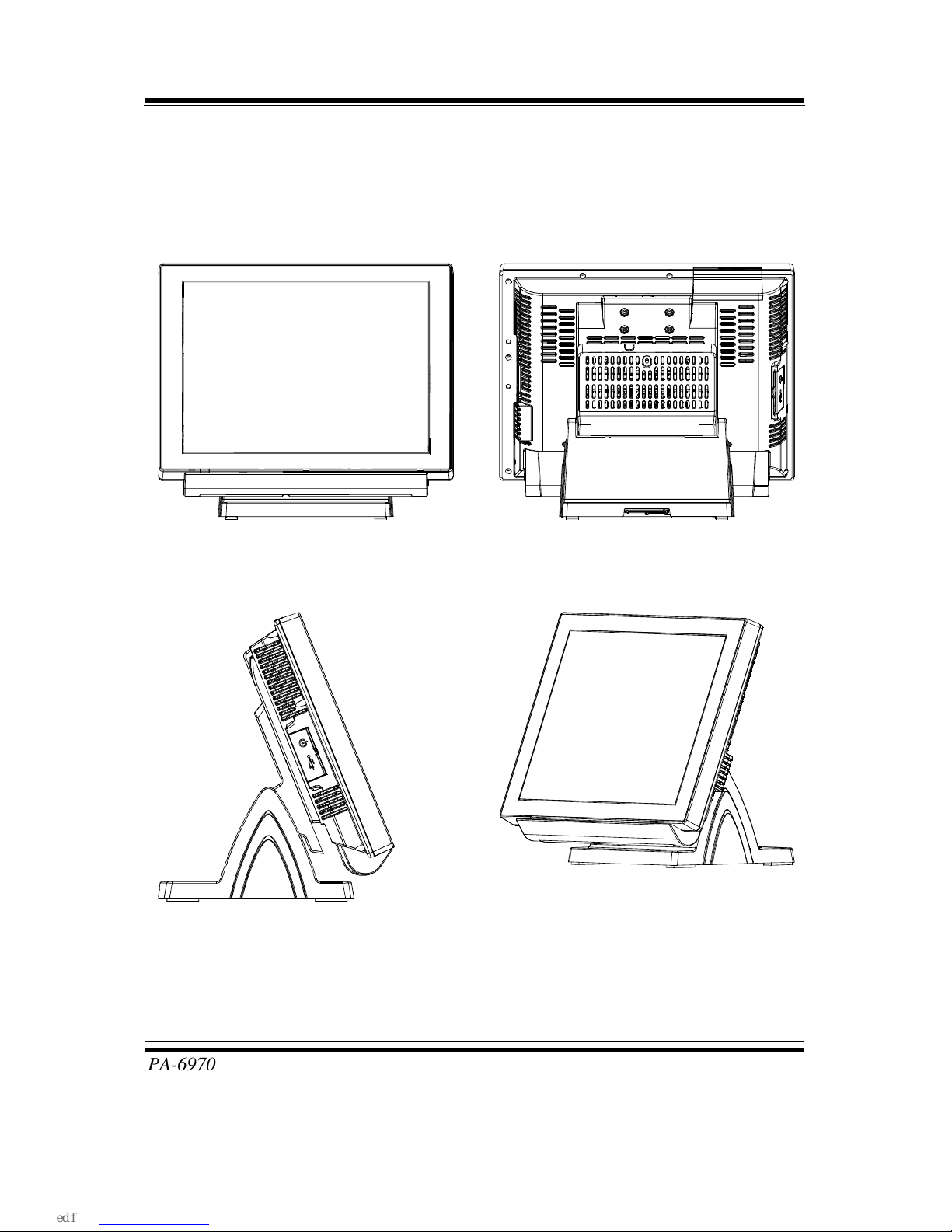
1-2. POS SYSTEM ILLUSTRATION
Front View Rear View
Side View Quarter View
Page 10

Chapter 1 Introduction
PA-6970 SERIES USER′S MANUAL
Page: 1-4
Rear I/O View
Page 11
Chapter 1 Introduction
PA-6970 SERIES USER′S MANUAL
Page: 1-5
1-3. SYSTEM SPECIFICATIONS
MAINBOARD (PB-3251)
System
CPU support
Intel® 3rd Gen. Core i5-3550S 3.0 GHz, L2
Cache-6MB
Intel® 3rd Gen. Core i3-3220S 3.3 GHz, L2
Cache-3MB
Intel® 2nd Gen. Core i3-2120 3.3 GHz, L2
Cache-3MB
Intel® Pentium® G850 2.9 GHz, L2 Cache-3MB
Intel® Celeron® G540 2.4 GHz, L2 Cache-2MB
Core Logic Intel® H61
Memory 1 x DDR3 SO-DIMM Slot (up to 4GB)
Network 10/100/1000 Base-T Fast Ethernet
OS Support Windows Embedded POSReady2009/7
Windows WES2009/7
Windows XP Pro/7
BIOS AMI SPI BIOS, 8Mbits with VGA BIOS
Power Supply 120 Watt power inside
System Weight 6.6 kg (POS), 5.3kg (PPC)
Dimension (W x H x D) 367mm x 318mm x 259mm (POS)
367 x 270 x 78mm (PPC)
Certificate FCC/CE
I/O Ports
USB 4 x USB2.0 ports
1 x USB2.0 on side bezel
Serial Port 3 x DB-9 (COM 2/3/4)
1 x RJ45 (COM1)
+5/12V Selectable
LAN 1 x RJ-45
Page 12
Chapter 1 Introduction
PA-6970 SERIES USER′S MANUAL
Page: 1-6
VGA 1 x DB-15 VGA Interface
Cash Drawer 1 x RJ11 (+12V/+24V selectable, default at +12V)
AC in For power cord plug
Line out 1 x phone jack
Keyboard & Mouse 1 x PS/2 (default at keyboard)
Storage
HDD 1 x 2.5” SATA HDD
SD 1 x 2.5” SATA SSD (Optional)
Display
LCD Interface 15” TFT
Max. Resolution 1024 x 768
Brightness 250 cd/m2
Tilt Angel 0~68˚
Touch Screen 5-wire Analog resistive
Environment
Temperature Operation: 0~35˚C (32~95˚F)
Storage: -20~60˚C (-4~140˚F)
Humidity 20~90%
Page 13

Chapter 1 Introduction
PA-6970 SERIES USER′S MANUAL
Page: 1-7
1-4. SAFETY PRECAUTIONS
The following messages are safety reminders on how to protect your systems from
damages, and extending the life cycle of the system.
1. Check the Line Voltage
a. The operating voltage for the power supply should be within the range of
100V to 240V AC; otherwise the system may be damaged.
2. Environmental Conditions
a. Place your PA-6970 on a sturdy, level surface. Be sure to allow enough
space around the system to have easy access needs.
b. Avoid installing your PA-6970 Series POS system in extremely hot or cold
places.
c. Avoid exposure to sunlight for a long period of time (for example, in a
closed car in summer time. Also avoid the system from any heating device.).
Or do not use the PA-6970 when it has been left outdoors in a cold winter
day.
d. Bear in mind that the operating ambient temperature is between 0˚C and
35˚C (32˚F and 95˚F).
e. Avoid moving the system rapidly from a hot place to a cold place, and vice
versa, because condensation may occur inside the system.
f. Protect your PA-6970 against strong vibrations, which may cause hard disk
failure.
g. Do not place the system too close to any radio-active device. Radio-active
device may cause signal interference.
h. Always shutdown the operating system before turning off the power.
3. Handling
a. Avoid placing heavy objects on the top of the system.
b. Do not turn the system upside down. This may cause the hard drive to
malfunction.
c. Do no allow any objects to fall into this product.
d. If water or other liquid spills into the product, unplug the power cord
immediately.
Page 14

Chapter 1 Introduction
PA-6970 SERIES USER′S MANUAL
Page: 1-8
4. Good Care
a. When the outside case gets stained, remove the stains using neutral washing
agent with a dry cloth.
b. Never use strong agents such as benzene and thinner to clean the surface of
the case.
c. If heavy stains are present, moisten a cloth with diluted neutral washing
agent or alcohol and then wipe thoroughly with a dry cloth.
d. If dust is accumulated on the case surface, remove it by using a special
vacuum cleaner for computers.
Page 15

Page 2-1
SYSTEM
CONFIGURATION
Helpful information that describes the jumper and connector settings,
and component locations.
Sections included:
Jumper & Connector Quick Reference Table
Component Locations
Configuration and Jumper settings
Connector Pin Assignments
CHAPTER
2
Page 16

Chapter 2 System Configuration
PA-6970 SERIES USER’S MANUAL
Page: 2-2
2-1. JUMPER & CONNECTOR QUICK REFERENCE TABLE
JUMPER / CONNECTOR NAME PAGE
COM Port & VGA Connector COM1, COM3-1, COM4-1, COM4-2,
JVGACOM2
2-7
COM Port RI and Voltage
Selection
JP_COM1, JP_COM2, JP_COM3,
JP_COM4
2-10
I-Button Connector JI-BUTTON1 2-10
I-Button Function Selection
JP14, JP15, JP16 2-11
LAN & USB Connector JRJ45USB23
2-12
Mini-DIN & USB Connector JPS2USB01 2-12
USB Connector USB5, USB 8, USB9;
USB10-1 & USB10-2 (both optional)
2-13
Cash Drawer Connector DRW1
2-15
Cash Drawer Power Selection JP13
2-16
LED Connector JLED1-1, JLED1-2, JLED2
2-17
Fan Connector FAN1, FAN2
2-18
Power Connector J1
2-19
Power Switch Connector SW1, SW2-1, SW2-2
2-19
Power for Thermal Printer
Connector
PRT_PWR1
2-20
External Speaker Connector SPK1, SPK2
2-20
Inverter Connector JINV1, JINV2, JINV3
2-21
LVDS Voltage Selection JP7
2-22
LVDS Connector LVDS1
2-23
MSR/Card Reader Connector PS2_1, PS2_2
2-23
SATA & SATA Power Connector SATA1, SATA2,
JPWR_4P1, JPWR_4P2
2-24
Touch Panel Connector TOUCH1, TOUCH2
2-25
Touch Panel Selection
JP6, JP27 2-26
Clear CMOS Data Selection JP2
2-27
Printer Connector LPT1
2-28
LVDS Output Resolution Selection JP22, JP23, JP24, JP25 2-29
Security Override Mode Setting JP26 2-29
LVDS Backlight Type Selection JP21 2-30
Page 17
Chapter 2 System Configuration
PA-6970 SERIES USER’S MANUAL
Page: 2-3
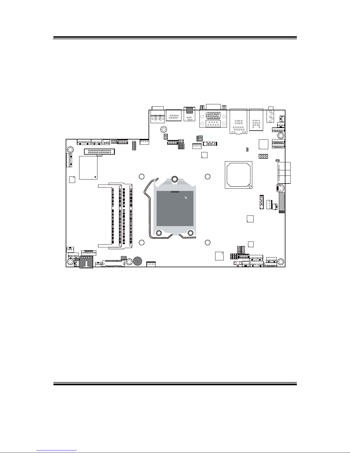
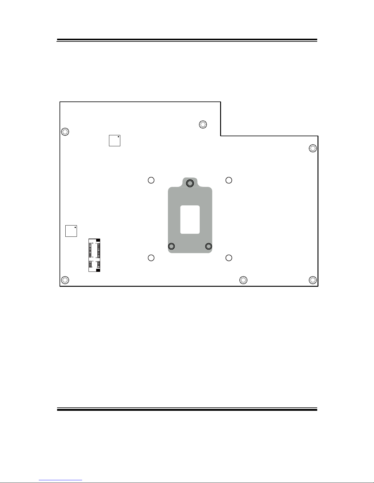
2-2. COMPONENT LOCATIONS
M/B: PB-3251
1
JP26
11
1
1 1 1
JP27
JP22
JP23
JP25
JP24
REMOVE
Intel
®
2nd Gen. Core™
CPU Socket
203
73
2
7271
74
1
204
DIMM1
203
73
2
7271
74
1
204
DIMM2
1
1
2
JLED1-1
JINV2
1 7
1 4
1
2
29
30
LVDS1
1
2
6
5
JP7
JP21
15
TOUCH1
1 2
SW2-1
SP1
FAN2
1 4
6 1
PS2_1
2
2
8
JP6
COM4-2
2
1
JI_BUTTON1
TOUCH2
1 5
USB5
1 5
JINV1
1 4
1 2
SPK1
Intel
H61
Battery
1
2
3
4
SW1
6 1
PS2_2
6 1
JINV3
1
2
3
4
5
LINE-OUT1
1
2
SW2-2
1 2
SPK2
1
1
4
4
USB10-1
USB10-2
6 1
JLED1-2
129
10
A1
A4
B1
B4
JRJ45USB23
2421
16
20
5
10
15
1
6
11
JVGACOM2
1
JPS2USB01
4
9
13 14
12
85
43
PWR_IN1
PWR_IN2
21
1 2 3 4
1
2 10
9
125
6
DRW1
COM1
1
2
6
5
JP_COM4
COM4-1
2
1
USB9
1 5
LPT1
26
13
14
1
J1
1
1 4
PRT_PWR1
FAN1
1 4
SIO
USB8
1
5
10 9
12
J_LPC1
1 7
SATA2
1 2
2
65
JP_COM1
1
JP13
1 2
65
JP_COM2
1
JP14
JP15
JP16
6
5
JP_COM3
COM3-1
9
10
JPWR_4P2
41
1
1
2
8
7
JP4
1
7
SATA1
J3GPWR1
JPWR_4P1
1
4
1
2
1
JP2
JLED2
JP21
JINVDRV1
1 2
PA-6970 Front Connector, Jumper and Component Locations
Page 18
Chapter 2 System Configuration
PA-6970 SERIES USER’S MANUAL
Page: 2-4
M_PCIE1
PA-6970 Rear Connector, Jumper and Component Locations
Page 19

Chapter 2 System Configuration
PA-6970 SERIES USER’S MANUAL
Page: 2-5
2-3. HOW TO SET THE JUMPERS
You can configure your board by setting the jumpers. A jumper consists of two or three
metal pins with a plastic base mounted on the card, and by using a small plastic "cap",
also known as the jumper cap (with a metal contact inside), you are able to connect the
pins. So you can set-up your hardware configuration by "opening" or "closing" pins.
Jumpers can be combined into sets that called jumper blocks. When jumpers are all in
the block, you have to put them together to set up the hardware configuration. The
figure below shows what this looks like.
JUMPERS AND CAPS
If a jumper has three pins for example, labelled PIN1, PIN2, and PIN3. You can
connect PIN1 & PIN2 to create one setting and shorting. You can either connect PIN2
& PIN3 to create another setting. The same jumper diagrams are applied all through
this manual. The figure below shows what the manual diagrams look and what they
represent.
Page 20
Chapter 2 System Configuration
PA-6970 SERIES USER’S MANUAL
Page: 2-6
JUMPER DIAGRAMS
JUMPER SETTINGS
Page 21
Chapter 2 System Configuration
PA-6970 SERIES USER’S MANUAL
Page: 2-7
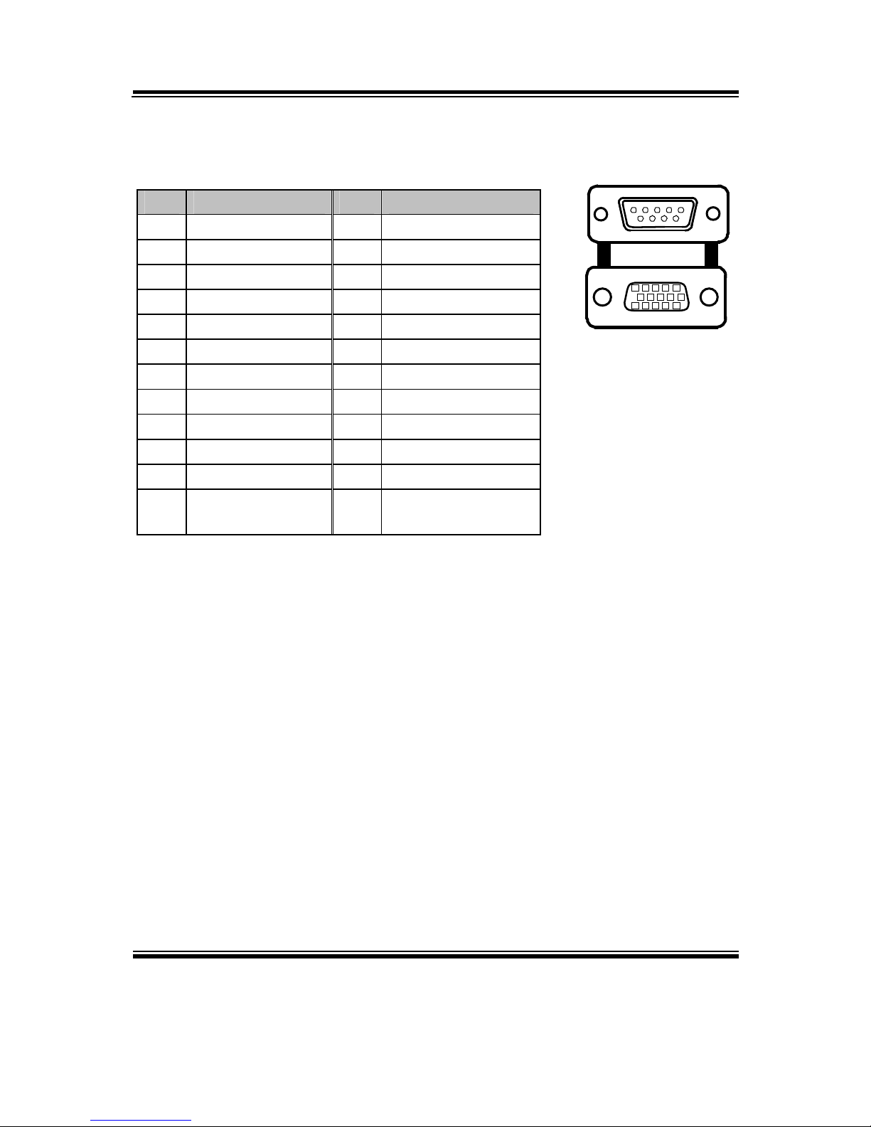
2-4. COM PORT & VGA CONNECTOR
There are four COM ports enhanced in this board namely: COM1, COM3-1, COM4-1,
COM4-2 and JVAGCOM2.
COM1: COM1 Connector
The pin assignments are as follows:
PIN ASSIGNMENT PIN ASSIGNMENT
1 DCD1 6 DSR1
2 RXD1 7 RTS1
3 TXD1 8 CTS1
4 DTR1 9 RI / +5V / +12V
selectable
5 GND 10 NC
COM3-1: COM3-1 Connectors
The pin assignments are as follows:
PIN ASSIGNMENT PIN ASSIGNMENT
1 DCD3 6 DSR3
2 RXD3 7 RTS3
3 TXD3 8 CTS3
4 DTR3 9 RI / +5V / +12V
selectable
5 GND 10 NC
COM1
210
1
9
Page 22
Chapter 2 System Configuration
PA-6970 SERIES USER’S MANUAL
Page: 2-8
COM4-1, COM4-2: COM4-1, COM4-2 Connectors
The pin assignments are as follows:
PIN ASSIGNMENT PIN ASSIGNMENT
1 DCD4 6 DSR4
2 RXD4 7 RTS4
3 TXD4 8 CTS4
4 DTR4 9 RI / +5V / +12V
selectable
5 GND 10 NC
Note: All COM ports are selectable for RI, +5V or +12V. For more information, please refer to
“2-5. COM RI & Voltage Selection” of this manual.
210
1
9
210
1
9
Page 23
Chapter 2 System Configuration
PA-6970 SERIES USER’S MANUAL
Page: 2-9
JVGACOM2: VGA & COM2 Connectors
The pin assignments are as follows:
PIN ASSIGNMENT PIN ASSIGNMENT
1 RED 13 HSYNC
2 GREEN 14 VSYNC
3 BLUE 15 DDCA CLK
4 NC 16 DCD2
5 GND 17 RXD2
6 GND 18 TXD2
7 GND 19 DTR2
8 GND 20 GND
9 +5V 21 DSR2
10 GND 22 RTS2
11 NC 23 CTS2
12 DDCA DATA 24 RI / +5V / +12V
selectable
Note: All COM ports are selectable for RI, +5V or +12V. For more information, please refer to
“2-5. COM RI & Voltage Selection” of this manual.
JVGACOM
2
16
21
20
24
15
10
15
6
11
Page 24
Chapter 2 System Configuration
PA-6970 SERIES USER’S MANUAL
Page: 2-10
2-5. COM PORT RI & VOLTAGE SELECTION
JP_COM1 , JP_COM2, JP_COM3, JP_COM4:
COM Port RI & Voltage Selection
The jumper settings are as follows:
SELECTION JUMPER
SETTING
JUMPER ILLUSTRATION
RI 1-2
21
65
21
65
216
5
561
2
VCC12 3-4
21
65
21
65
216
5
561
2
VCC 5-6
21
65
21
65
216
5
561
2
Note: Manufacturing Default is RI.
2-6. I-BUTTON CONNECTOR
JI-BUTTON1: i-Button Connector
The pin assignments are as follows:
PIN ASSIGNMENT
1 COM3_DTR_R_I
2 COM3_RXD_R_I
Page 25
Chapter 2 System Configuration
PA-6970 SERIES USER’S MANUAL
Page: 2-11
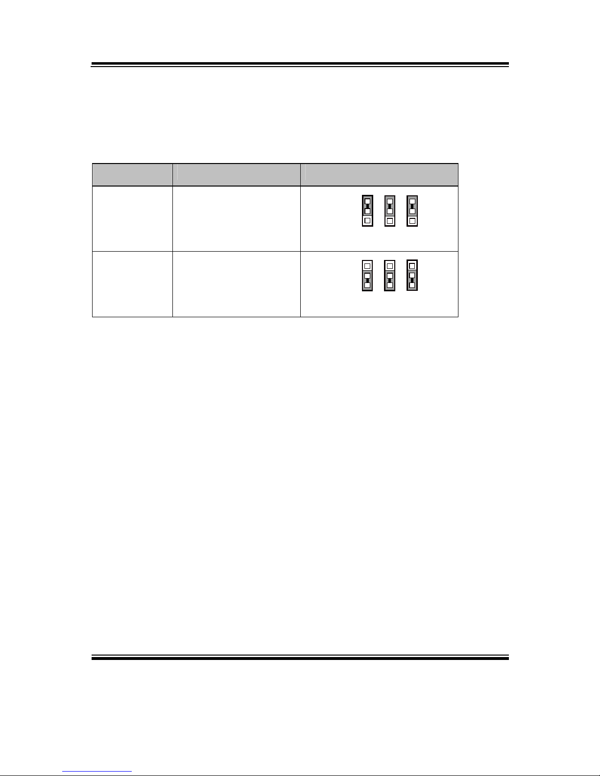
2-7. I-BUTTON FUNCTION SELECTION
JP14, JP15, JP16: i-Button Function Selection
The jumper settings are as follows:
SELECTION JUMPER SETTING JUMPER ILLUSTRATION
COM 3 1-2
JP14/15/16
111
i-Button* 2-3
JP14/15/16
111
Note: Manufacturing Default is COM3.
*When these jumpers are set as ‘i-Button,’ the COM3-1 connector will not function.
Page 26
Chapter 2 System Configuration
PA-6970 SERIES USER’S MANUAL
Page: 2-12
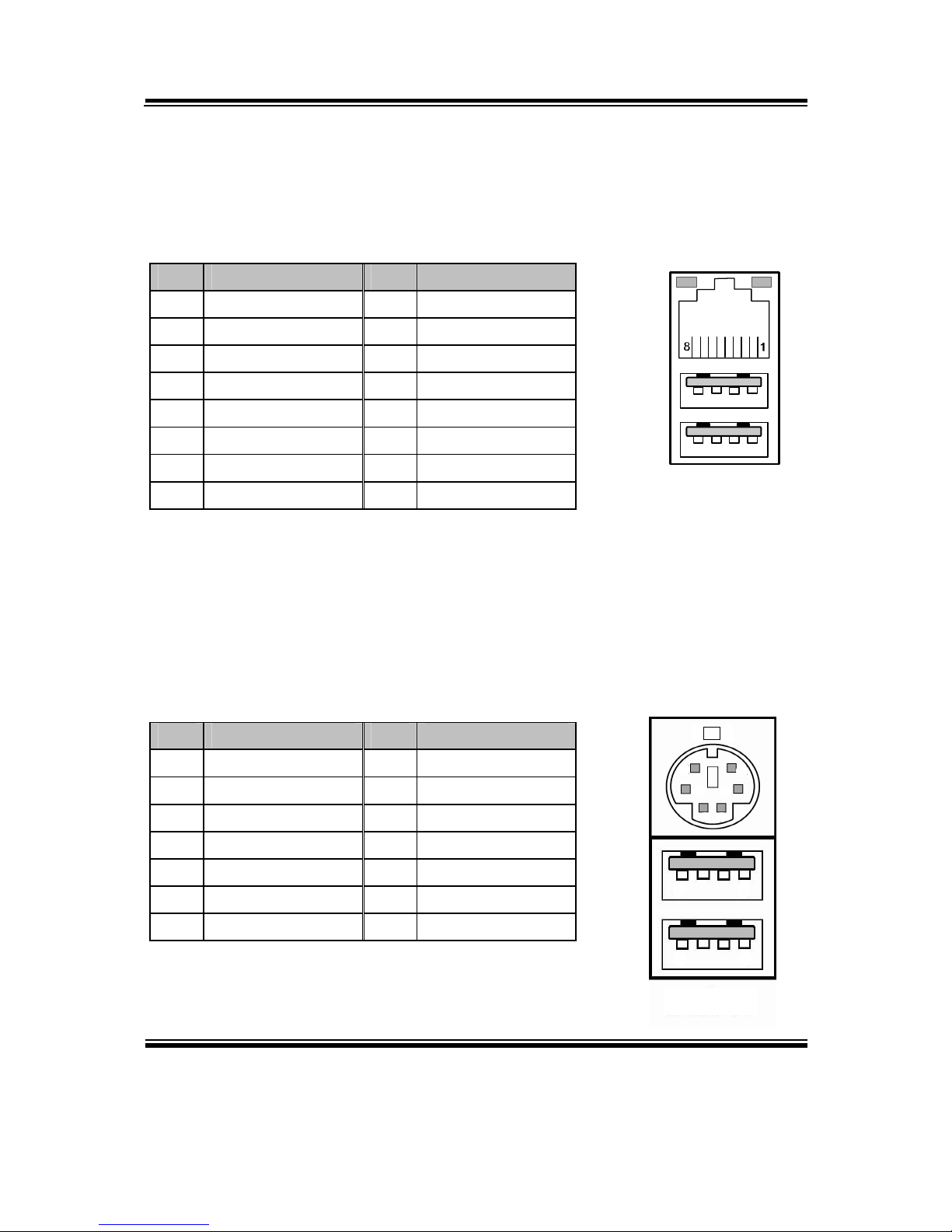
2-8. LAN & USB CONNECTOR
JRJ45USB23: LAN & USB Connector
The pin assignments are as follows:
PIN ASSIGNMENT PIN ASSIGNMENT
1 LAN1_MDIP0 A1 VCC5
2 LAN1_MDIN0 A2 USB2-
3 LAN1_MDIP1 A3 USB2+
4 LAN1_MDIN1 A4 GND
5 LAN1_MDIP2 B1 VCC5
6 LAN1_MDIN2 B2 USB3-
7 LAN1_MDIP3 B3 USB3+
8 LAN1_MDIN3 B4 GND
2-9. MINI-DIN & USB CONNECTOR
JPS2USB01: MINI-DIN and USB Connectors
The MINI-DIN connector can support keyboard, Y-cable, or PS/2 Mouse.
The pin assignments are as follows:
PIN ASSIGNMENT PIN ASSIGNMENT
1 GND 8 VCC5
2 USB0+ 9 GND
3 USB0- 10 KDAT
4 VCC5 11 MDAT
5 GND 12 V5SB
6 USB1+ 13 KCLK
7 USB1- 14 MCLK
JRJ45
USB23
Orang
e
Green
A4
A1
B4B1
10
11
12
9
1314
1
4
5
8
JPS2USB01
MS
Page 27
Chapter 2 System Configuration
PA-6970 SERIES USER’S MANUAL
Page: 2-13
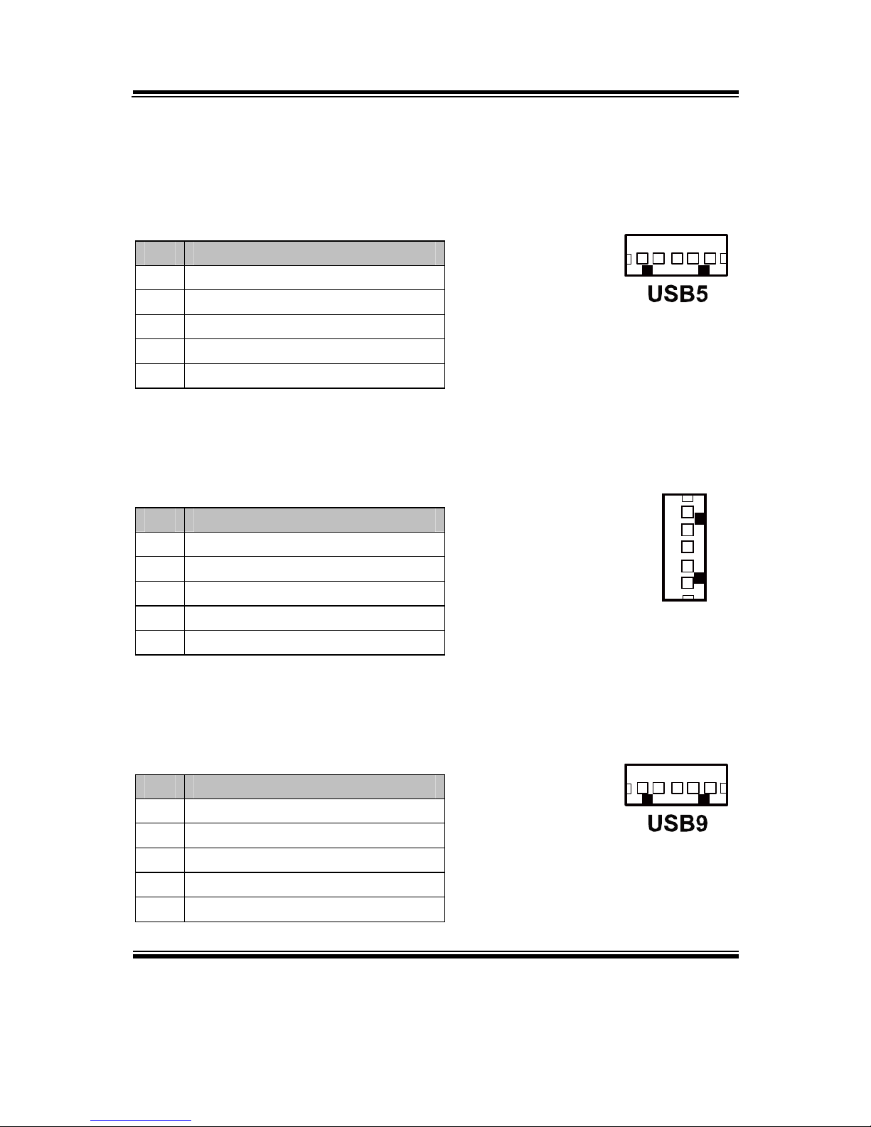
2-10. USB CONNECTOR
USB5: Internal USB Connector
The pin assignments are as follows:
PIN ASSIGNMENT
1 USB52 USB5+
3 GND
4 5V
5 GND
USB8: Internal USB Connector
The pin assignments are as follows:
PIN ASSIGNMENT
1 USB82 USB8+
3 GND
4 5V
5 GND
USB9: Internal USB Connector
The pin assignments are as follows:
PIN ASSIGNMENT
1 USB92 USB9+
3 GND
4 5V
5 GND
1 5
USB8
1
5
1 5
Page 28

Chapter 2 System Configuration
PA-6970 SERIES USER’S MANUAL
Page: 2-14
USB10-1, USB10-2 (Optional): Two USB Connectors
The pin assignments are as follows:
PIN ASSIGNMENT
1 5V
2 USB103 USB10+
4 GND
U
SB10-1
41
41
U
SB10-2
Page 29

Chapter 2 System Configuration
PA-6970 SERIES USER’S MANUAL
Page: 2-15
2-11. CASH DRAWER CONNECTOR
DRW1: Cash Drawer Connector
The pin assignments are as follows:
PIN ASSIGNMENT
1 GND
2 Drawer Open
3 Drawer Sense
4 +12V
5 NC
6 GND
PB-3251 cash drawer control in GPIO port
To Open Drawer1 (GPIO 7):
Write "0"h to I/O space register "50C"h Bit 7
To Close Drawer1
Write "1"h to I/O space register "50C"h Bit 7
Detect Drawer1 Status
Read I/O space register "50C"h (GPIO 6)
Definition (bit4)
Page 30
Chapter 2 System Configuration
PA-6970 SERIES USER’S MANUAL
Page: 2-16
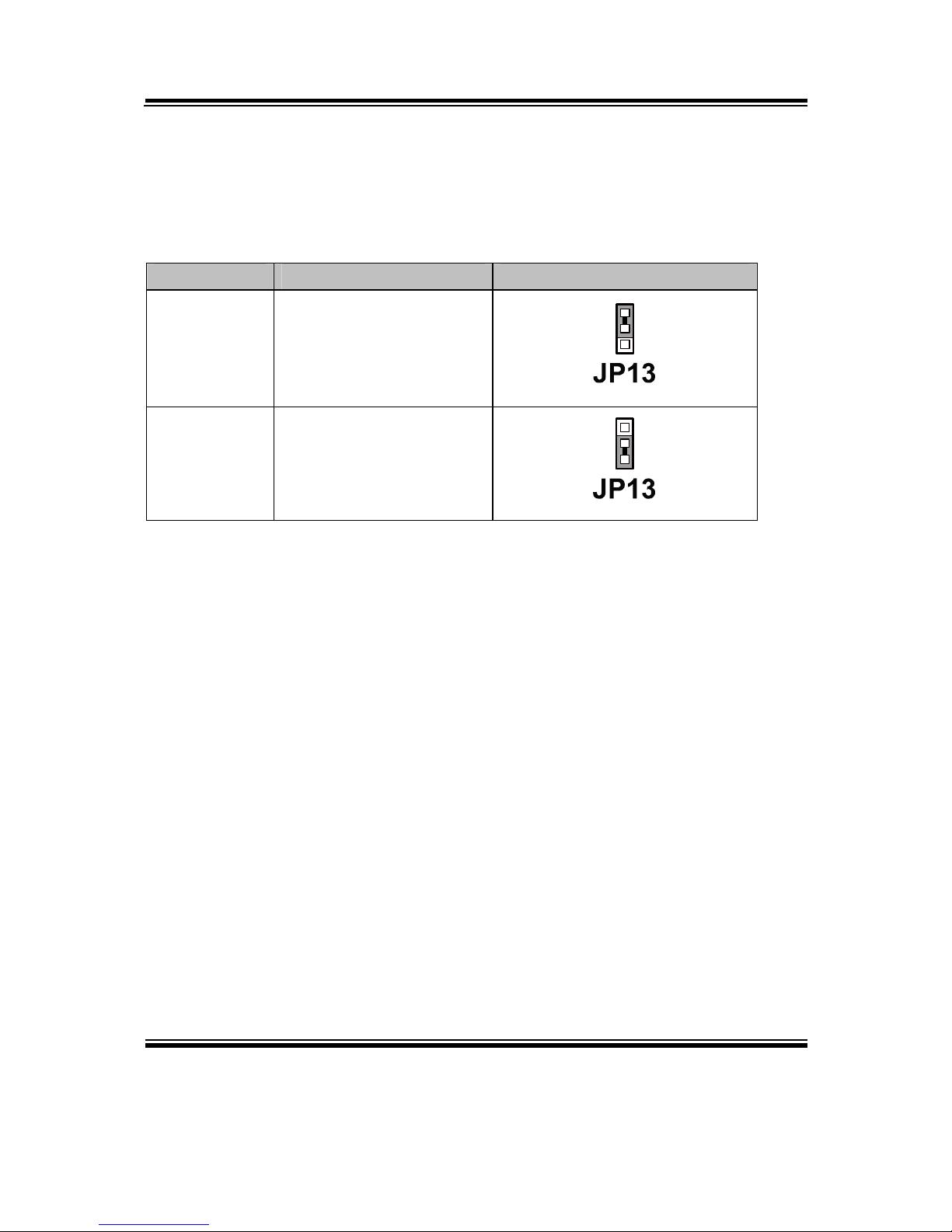
2-12. CASH DRAWER POWER SELECTION
JP13: Cash Drawer Power Selection
The jumper settings are as follows:
SELECTION JUMPER SETTING JUMPER ILLUSTRATION
+24V 1-2
1
+12V 2-3
1
Note: Manufacturing Default is +24V.
Page 31
Chapter 2 System Configuration
PA-6970 SERIES USER’S MANUAL
Page: 2-17
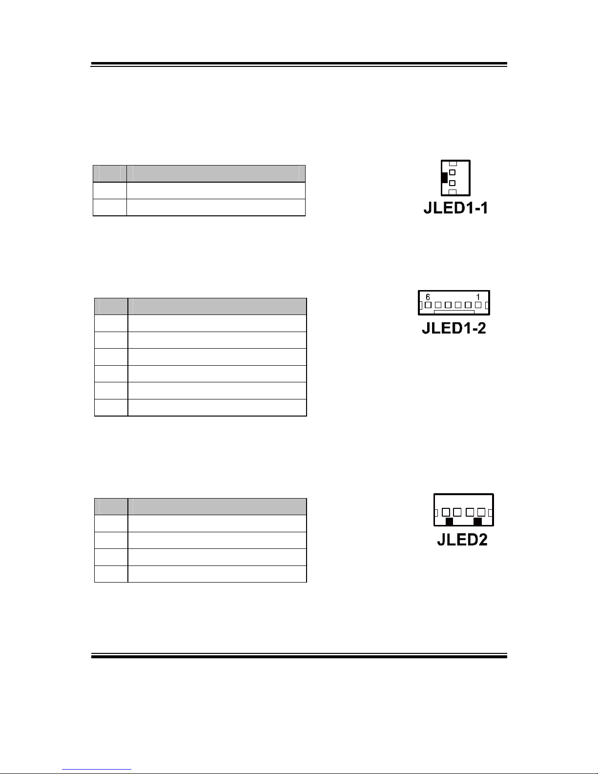
2-13. LED CONNECTOR
JLED1-1: Power indication LED Connector
The pin assignments are as follows:
PIN ASSIGNMENT
1 PWR_LED
2 5V
JLED1-2: Power, HDD, LAN indication LED Connector
The pin assignments are as follows:
PIN ASSIGNMENT
1 5V
2 PWR_LED
3 3.3V
4 HDD_LED
5 LAN1_LINK_ACTJ
6 LAN1_LED0
JLED2: Power indication LED Connector
The pin assignments are as follows:
PIN ASSIGNMENT
1 5V
2 HD_LED
3 PWR_LED
4 3.3V
1
2
1 4
Page 32
Chapter 2 System Configuration
PA-6970 SERIES USER’S MANUAL
Page: 2-18
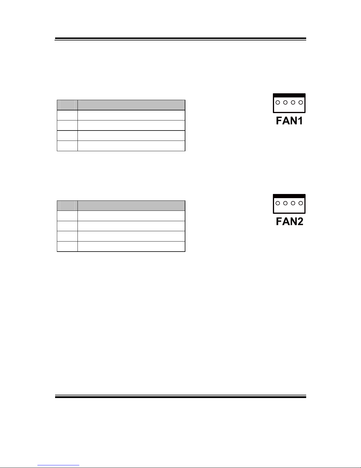
2-14. FAN CONNECTOR
FAN1: System Fan Connector
The pin assignments are as follows:
PIN ASSIGNMENT
1 GND
2 VCC12
3 SYS_FANIN
4 SYS_FANOUT
FAN2: CPU Fan Connector
The pin assignments are as follows:
PIN ASSIGNMENT
1 GND
2 VCC12
3 SYS_FANIN
4 SYS_FANOUT
1 4
1 4
Page 33

Chapter 2 System Configuration
PA-6970 SERIES USER’S MANUAL
Page: 2-19
2-15. POWER CONNECTOR
J1: Provide 12 Voltage Connector
The pin assignments are as follows:
PIN ASSIGNMENT
1 VCC12
2 GND
3 VCC12
2-16. POWER SWITCH CONNECTOR
SW1, SW2-1, SW2-2: Power Switch Connectors
The pin assignments are as follows:
PIN ASSIGNMENT
1 LPC_PWRBTNJ
2 PCH_PWRBTNJ_LOW
SW1/
SW2-2
1
2
SW2-1
1 2
Page 34

Chapter 2 System Configuration
PA-6970 SERIES USER’S MANUAL
Page: 2-20
2-17. POWER FOR THERMAL PRINTER CONNECTOR
PRT_PWR1: Power for Thermal Printer Connector
The pin assignments are as follows:
PIN ASSIGNMENT
1 VCC24SB
2 VCC24SB
3 GND
4 GND
2-18. EXTERNAL SPEAKER CONNECTOR
SPK1, SPK2: External Speaker Connectors
The pin assignments are as follows:
PIN ASSIGNMENT
1 SPK_GND
2 SPK_OUT
1 4
1 2
SPK1/
SPK2
Page 35

Chapter 2 System Configuration
PA-6970 SERIES USER’S MANUAL
Page: 2-21
2-19. INVERTER CONNECTOR
JINV1: Inverter Connector
The pin assignments are as follows:
PIN ASSIGNMENT
1 +12V
2 GND
3 LVDS_BKLTEN
4 BRCTR
JINV2: Inverter Connector
The pin assignments are as follows:
PIN ASSIGNMENT
1 +12V
2 +12V
3 GND
4 GND
5 LVDS_BKLTEN_R
6 BRCTR
7 GND
JINV3: Inverter Connector
The pin assignments are as follows:
PIN ASSIGNMENT
1 +12V
2 GND
3 GND
4 BRCTR
5 LVDS_BKLTEN
6 +12V
1 4
1
7
Page 36

Chapter 2 System Configuration
PA-6970 SERIES USER’S MANUAL
Page: 2-22
2-20. LVDS VOLTAGE SELECTION
JP7: LVDS Voltage Selection
The jumper settings are as follows:
SELECTION JUMPER SETTING JUMPER ILLUSTRATION
3.3V
1-3
2-4
5
6
1
2
5V
3-5
4-6
5
6
1
2
Note: Manufacturing Default is 3.3V.
Page 37

Chapter 2 System Configuration
PA-6970 SERIES USER’S MANUAL
Page: 2-23
2-21. LVDS CONNECTOR
LVDS1: LVDS Connector
The pin assignments are as follows:
PIN ASSIGNMENT PIN ASSIGNMENT
1 LVDS_VCC 16 CLKO+
2 GND 17 CLKO3 NC 18 GND
4 NC 19 RINO2+
5 GND 20 RINO26 NC 21 GND
7 NC 22 RINO1+
8 GND 23 RINO19 NC 24 GND
10 NC 25 RINO0+
11 NC 26 RINO012 NC 27 NC
13 NC 28 NC
14 NC 29 LVDS_VCC
15 GND 30 LVDS_VCC
2-22. MSR/CARD READER CONNECTOR
PS2_1 & PS2_2: MSR/Card Reader Connector
The pin assignments are as follows:
PIN ASSIGNMENT
1 KB_CLK (Output)
2 KB_CLK_C (Input)
3 KB_DATA_C (Input)
4 KB_DATA (Output)
5 +5V
6 GND
PS2_1/
PS2_2
6 1
Page 38

Chapter 2 System Configuration
PA-6970 SERIES USER’S MANUAL
Page: 2-24
2-23. SATA & SATA POWER CONNECTOR
SATA1, SATA2: Serial ATA Connectors
The pin assignments are as follows:
PIN ASSIGNMENT
1 G1
2 TX+
3 TX-
4 G2
5 RX-
6 RX+
7 G3
JPWR_4P1, JPWR_4P2: Serial ATA Power Connectors
The pin assignments are as follows:
PIN ASSIGNMENT
1 VCC
2 GND
3 GND
4 VCC12
S
AT
A1
1
7
SATA2
1 7
JPWR_4P1
1
4
JPWR_4P2
1 4
Page 39
Chapter 2 System Configuration
PA-6970 SERIES USER’S MANUAL
Page: 2-25
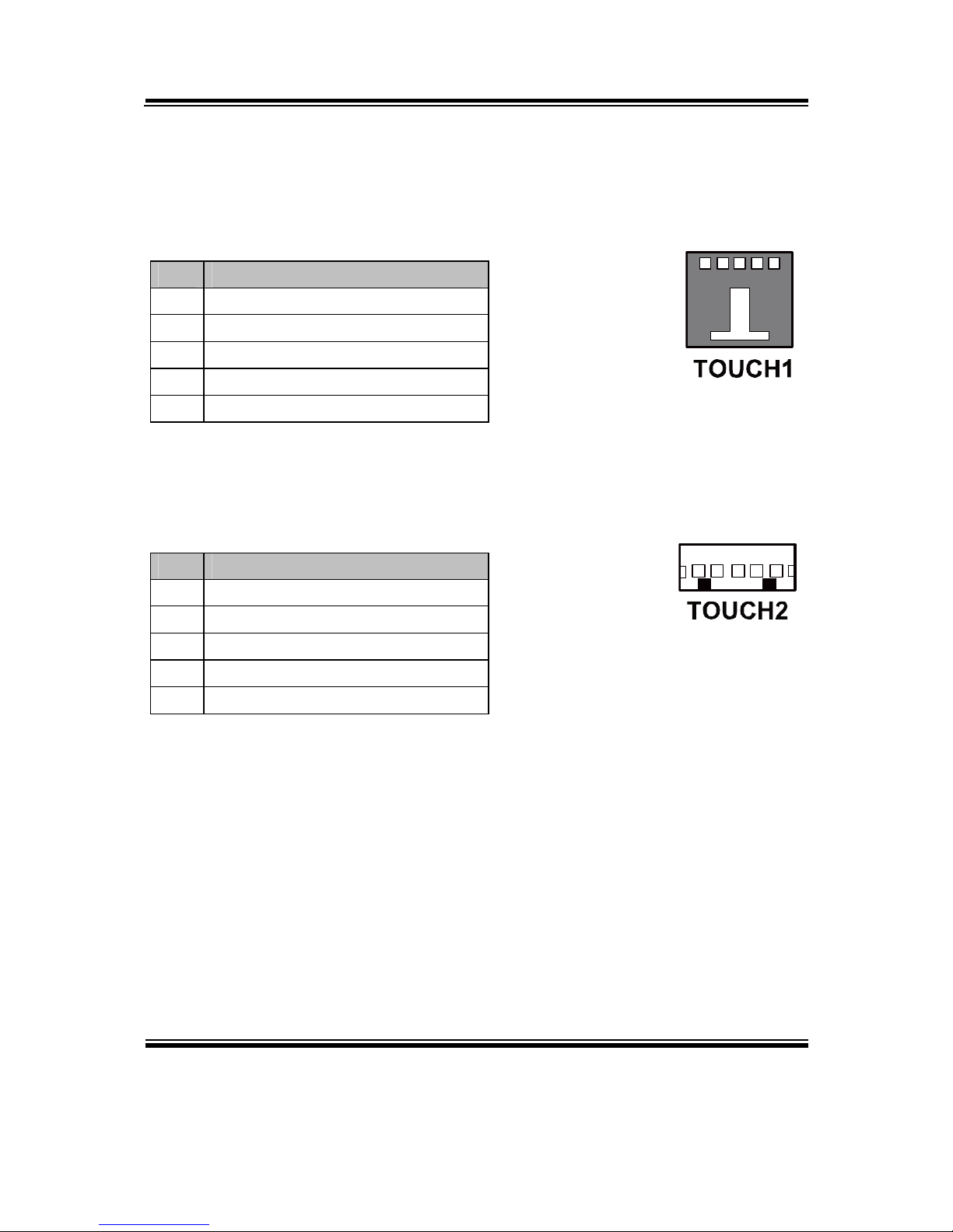
2-24. TOUCH PANEL CONNECTOR
TOUCH1: Touch Panel Connector
The pin assignments are as follows:
PIN ASSIGNMENT
1 LR (Low Right)
2 LL (Low Left)
3 Probe
4 UR (Up Right)
5 UL (Up Left)
TOUCH2: Touch Panel Connector
The pin assignments are as follows:
PIN ASSIGNMENT
1 LR (Low Right)
2 LL (Low Left)
3 Probe
4 UR (Up Right)
5 UL (Up Left)
JP21
15
1 5
Page 40

Chapter 2 System Configuration
PA-6970 SERIES USER’S MANUAL
Page: 2-26
2-25. TOUCH PANEL SELECTION
JP6: Touch Panel Selection
The jumper settings are as follows:
SELECTION JUMPER SETTING JUMPER ILLUSTRATION
Elo
1-2
5-6
1
2
7
8
JP6
e-Turbo
3-4
7-8
1
2
7
8
JP6
Note: Manufacturing Default is Elo.
JP27: Touch Panel Selection
The jumper settings are as follows:
SELECTION JUMPER SETTING JUMPER ILLUSTRATION
Elo
1-2
5-6
1
2
7
8
JP27
3M
3-4
7-8
1
2
7
8
JP27
Note: Manufacturing Default is Elo.
Page 41

Chapter 2 System Configuration
PA-6970 SERIES USER’S MANUAL
Page: 2-27
2-26. CLEAR CMOS DATA SELECTION
JP2: Clear CMOS Data Selection
The jumper settings are as follows:
SELECTION JUMPER SETTING JUMPER ILLUSTRATION
Normal Open
1
Clear CMOS*
1-2
1
Note: Manufacturing Default is Normal.
*To clear CMOS data, you must power-off the computer and set the jumper to
“Clear CMOS” as illustrated above. After five to six seconds, set the jumper back
to “Normal” and power-on the computer.
Page 42

Chapter 2 System Configuration
PA-6970 SERIES USER’S MANUAL
Page: 2-28
2-27. PRINTER CONNECTOR
LPT1: LPT Connector
The pin assignments are as follows:
PIN ASSIGNMENT PIN ASSIGNMENT
1 STBJ 14 ALFJ
2 PDR0 15 ERRJ
3 PDR1 16 PAR_INITJ
4 PDR2 17 SLCTINJ
5 PDR3 18 GND
6 PDR4 19 GND
7 PDR5 20 GND
8 PDR6 21 GND
9 PDR7 22 GND
10 ACKJ 23 GND
11 BUSY 24 GND
12 PE 25 GND
13 SLCTJ 26 NC
Page 43

Chapter 2 System Configuration
PA-6970 SERIES USER’S MANUAL
Page: 2-29
2-28. LVDS OUTPUT RESOLUTION SELECTION
JP22, JP23, JP24, JP25: LVDS Output Resolution Selection
The jumper settings are as follows:
SELECTION JUMPER
SETTING
JUMPER ILLUSTRATION
15" 24bit
1024 x768
JP22 (2,3)
JP23 (1,2)
JP24 (2,3)
JP25 (2,3)
3
1
JP22
3
1
JP23
3
1
JP24
3
1
JP25
15" 18bit
1024 x768
JP22 (1,2)
JP23 (2,3)
JP24 (2,3)
JP25 (2,3)
3
1
JP22
3
1
JP23
3
1
JP24
3
1
JP25
Note: Manufacturing Default is 15" 24bit 1024 x768.
2-29. SECURITY OVERRIDE MODE SETTING
JP26: Flash Descriptor Security Override/Intel ME Debug Mode
The jumper settings are as follows:
SELECTION JUMPER SETTING JUMPER ILLUSTRATION
Disable Open
1
JP26
Enable 1-2
1
JP26
Note: Manufacturing Default is Disable.
Page 44

Chapter 2 System Configuration
PA-6970 SERIES USER’S MANUAL
Page: 2-30
2-30. LVDS BACKLIGHT TYPE SELECTION
JP21: LVDS Backlight Type Selection
The jumper settings are as follows:
SELECTION JUMPER SETTING JUMPER ILLUSTRATION
LED 1-2
1
3
JP21
CCFL 2-3
1
3
JP21
Note: Manufacturing Default is LED.
Page 45

Page: 3-1
SOFTWARE
UTILITIES
This chapter provides the detailed information users need to install
driver utilities for the system.
Sections included:
Intel® Chipset Software Installation Utility
VGA Driver Utility
LAN Driver Utility
Sound Driver Utility
Touch Screen Driver Utility
Wireless Driver Utility (Optional)
CHAPTER
3
Page 46

Chapter 3 Software Utilities
PA-6970 SERIES USER′S MANUAL
Page:3-2
3-1. INTRODUCTION
Enclosed with the PA-6970 Series package is our driver utilities, which comes in a
CD ROM format. Refer to the following table for driver locations.
FILENAME
(Assume that CD ROM drive is D:)
PURPOSE
D:\Driver\Plaform\XP,POSReady2009 (32-bit)\Main
Chip
D:\Driver\Plaform\Win7,POSReady7 (32-bit)\Main Chip
D:\Driver\Plaform\Win7,POSReady7 (64-bit)\Main Chip
Intel® Chipset Software
Installation Utility
D:\Driver\Plaform\XP,POSReady2009(32-bit)\VGA
D:\Driver\Plaform\Win7,POSReady7(32-bit)\VGA
D:\Driver\Plaform\Win7,POSReady7(64-bit)\VGA
Intel® HD Graphics for
VGA driver installation
D:\Driver\Plaform\XP,POSReady2009(32-bit)\LAN
D:\Driver\Plaform\Win7,POSReady7(32-bit)\LAN
D:\Driver\Plaform\Win7,POSReady7(64-bit)\LAN
Realtek RTL8111F for
LAN driver installation
D:\Driver\Plaform\XP,POSReady2009(32-bit)\Sound
D:\Driver\Plaform\Win7,POSReady7(32-bit)\Sound
D:\Driver\Plaform\Win7,POSReady7(64-bit)\Sound
Realtek ALC888S High
Definition Audio
Codecs for
Sound driver
installation
D:\Driver\Plaform\XP,POSReady2009(32-bit)\ME_SW
D:\Driver\Plaform\Win7,POSReady7(32-bit)\ME_SW
D:\Driver\Plaform\Win7,POSReady7(64-bit)\ME_SW
Intel® Management
Engine Interface
Installation
D:\Driver\Flash BIOS Aptio (EFI) BIOS
update utility
D:\Driver\Device Driver installation for
touch screen,
embedded
printer, wireless, MSR,
etc.
Note: Be sure to install the driver utilities right after the OS is fully installed.
Page 47

Chapter 3 Software Utilities
PA-6970 SERIES USER′S MANUAL
Page:3-3
3-2. INTEL® CHIPSET SOFTWARE INSTALLATION UTILITY
3-2-1. Introduction
The Intel® Chipset Software Installation Utility installs to the target system the
Windows* INF files that outline to the operating system how the chipset
components will be configured. This is needed for the proper functioning of the
following features.
- Core PCI and ISAPNP Services
- AGP Support
- SATA Storage Support
- USB Support
- Identification of Intel® Chipset Components in Device Manager
3-2-2. Installation of Intel
®
Chipset Driver
The utility pack is to be installed only for Windows XP/7 series, and it should be
installed right after the OS installation. Please follow the steps below:
1. Connect the USB-CD ROM device to PA-6970 and insert the driver disk inside.
2. Enter the “Main Chip” folder where the Chipset driver is located (depending on
your OS platform).
3. Click Setup.exe file for driver installation.
4. Follow the on-screen instructions to complete the installation.
5. Once installation is completed, shut down the system and restart the PA-6970 for
the changes to take effect.
Page 48

Chapter 3 Software Utilities
PA-6970 SERIES USER′S MANUAL
Page:3-4
3-3. VGA DRIVER UTILITY
The VGA interface embedded with the PA-6970 series can support a wide range of
display types. You can have dual displays via CRT and LVDS interfaces work
simultaneously.
1. Win XP Series
2. Win 7 SerIes
3. POSReady 2009
4. POSReady 7
3-3-1. Installation of VGA Driver
To install the VGA Driver, follow the steps below:
1. Connect the USB-CD ROM device to PA-6970 and insert the driver disk inside.
2. Enter the “VGA” folder where the VGA driver is located (depending on your OS
platform).
3. Click Setup.exe file for driver installation.
4. Follow the on-screen instructions to complete the installation.
5. Once installation is completed, shut down the system and restart the PA-6970 for
the changes to take effect.
Page 49

Chapter 3 Software Utilities
PA-6970 SERIES USER′S MANUAL
Page:3-5
3-4. LAN DRIVER UTILITY
The PA-6970 Series is enhanced with LAN function that can support various network
adapters. Installation platform for the LAN driver is listed as follows:
1. Win XP Series
2. Win 7 Series
3. POSReady 2009
4. POSReady 7
For more details on the Installation procedure, please refer to the Readme.txt file
found on LAN Driver Utility.
3-4-1. Installation of LAN Driver
To install the LAN Driver, follow the steps below:
1. Connect the USB-CD ROM device to PA-6970 and insert the driver disk inside.
2. Enter the “LAN” folder where the LAN driver is located (depending on your OS
platform).
3. Click Setup.exe file for driver installation.
4. Follow the on-screen instructions to complete the installation.
5. Once installation is completed, shut down the system and restart the PA-6970 for
the changes to take effect.
Page 50

Chapter 3 Software Utilities
PA-6970 SERIES USER′S MANUAL
Page:3-6
3-5. SOUND DRIVER UTILITY
The sound function enhanced in this system is fully compatible with Windows XP/7
series. Below, you will find the content of the Sound driver.
1. Win XP Series
2. Win 7 Series
3. POSReady 2009
4. POSReady 7
3-5-1. Installation of Sound Driver
To install the Sound Driver, refer to the readme.txt file on the driver disc
(:\Sound\Realtek\Readme.txt).
1. Connect the USB-CD ROM device to PA-6970 and insert the driver disk inside.
2. Enter the “Sound” folder where the Sound driver is located (depending on your OS
platform).
3. Click Setup.exe file for driver installation.
4. Follow the on-screen instructions to complete the installation.
5. Once installation is completed, shut down the system and restart the PA-6970 for
the changes to take effect.
Page 51

Chapter 3 Software Utilities
PA-6970 SERIES USER′S MANUAL
Page:3-7
3-6. TOUCH SCREEN DRIVER UTILITY
The touch screen driver utility can only be installed on a Windows platform (XP/7
series), and it should be installed right after the OS installation.
1. Win XP Series
2. Win 7 Series
3. POSReady 2009
4. POSReady 7
3-6-1. Installation of Touch Screen Driver
To install the Touch Screen Driver, follow the steps below:
1. Connect the USB-CD ROM device to PA-6970 and insert the driver disk inside.
2. Enter the “Device/Touchscreen” folder where the Touch Screen Driver is located.
3. Click Setup.exe file for driver installation.
4. Follow the on-screen instructions to complete the installation.
5. Once installation is completed, shut down the system and restart the PA-6970 for
the changes to take effect.
Page 52

Chapter 3 Software Utilities
PA-6970 SERIES USER′S MANUAL
Page:3-8
3-7. WIRELESS DRIVER UTILITY (OPTIONAL)
The wireless driver utility can only be installed on a Windows platform (XP/7 series,
POSReady 2009/7), and it should be installed right after the OS installation.
1. Win XP Series
2. Win 7 Series
3. POSReady 2009
4. POSReady 7
3-7-1. Installation of Wireless Driver
To install the Wireless Driver, follow the steps below:
1. Connect the USB-CD ROM device to PA-6970 and insert the driver disk inside.
2. Enter the “Device/Embedded Wireless Module” folder where the Wireless driver is
located.
3. Click Setup.exe file for driver installation.
4. Follow the on-screen instructions to complete the installation.
5. Once installation is completed, shut down the system and restart the PA-6970 for
the changes to take effect.
Page 53

Page: 4-1
AMI
BIOS SETUP
This chapter shows how to set up the AMI BIOS.
Sections included:
Introduction
Entering Setup
Main
Advanced
Chipset
Boot
Security
Save & Exit
CHAPTER
4
Page 54

Chapter 4 AMI BIOS Setup
PA-6970 SERIES USER′S MANUAL
Page: 4-2
4-1. INTRODUCTION
The system PA-6970 uses an AMI Aptio BIOS that is stored in the Serial Peripheral
Interface Flash Memory (SPI Flash) and can be updated. The SPI Flash contains the
BIOS Setup program, Power-on Self-Test (POST), the PCI auto-configuration utility,
LAN EEPROM information, and Plug and Play support.
Aptio is AMI’s BIOS firmware based on the UEFI (Unified Extensible Firmware
Interface) Specifications and the Intel Platform Innovation Framework for EFI. The
UEFI specification defines an interface between an operating system and platform
firmware. The interface consists of data tables that contain platform-related
information, boot service calls, and runtime service calls that are available to the
operating system and its loader. These provide standard environment for booting an
operating system and running pre-boot applications.
Following illustration shows Extensible Firmware Interface’s position in the software
stack.
Page 55

Chapter 4 AMI BIOS Setup
PA-6970 SERIES USER′S MANUAL
Page: 4-3
EFI BIOS provides an user interface allow users the ability to modify hardware
configuration, e.g. change system date and time, enable or disable a system component,
decide bootable device priorities, setup personal password, etc., which is convenient
for modifications and customization of the computer system and allows technicians
another method for finding solutions if hardware has any problems.
The BIOS Setup program can be used to view and change the BIOS settings for the
computer. The BIOS Setup program is accessed by pressing the <Del> or <ESC> key
after the POST memory test begins and before the operating system boot begins. The
settings are shown below.
Page 56

Chapter 4 AMI BIOS Setup
PA-6970 SERIES USER′S MANUAL
Page: 4-4
4-2. ENTERING SETUP
When the system is powered on, the BIOS will enter the Power-On Self Test (POST)
routines and the following message will appear on the lower screen:
POST Screen
As long as this message is present on the screen you may press the <Del> or <ESC>
key to access the Setup program.
Page 57
Chapter 4 AMI BIOS Setup
PA-6970 SERIES USER′S MANUAL
Page: 4-5
In a moment, the main menu of the Aptio Setup Utility will appear on the screen:
Setup program initial screen
You may move the cursor by up/down keys to highlight the individual menu items.
As you highlight each item, a brief description of the highlighted selection will
appear at the bottom of the screen.
Page 58

Chapter 4 AMI BIOS Setup
PA-6970 SERIES USER′S MANUAL
Page: 4-6
4-3. MAIN
Main screen
BIOS Setting Options Description/Purpose
BIOS Vendor No changeable options Displays the BIOS vendor.
Core Version No changeable options Displays the current BIOS core
version.
Compliancy No changeable options Displays the current UEFI version.
Project Version No changeable options Displays the version of the BIOS
currently installed on the platform.
Build Date and
Time
No changeable options Displays the date of current BIOS
version.
ME FW
Version
No changeable options Displays the current ME version.
ME Firmware
SKU
No changeable options Displays the current ME SKU.
Page 59

Chapter 4 AMI BIOS Setup
PA-6970 SERIES USER′S MANUAL
Page: 4-7
BIOS Setting Options Description/Purpose
System
Language
English BIOS Setup language.
System Date Month, day, year Specifies the current date.
System Time Hour, minute, second Specifies the current time.
Access Level No changeable options Displays the current user level.
Page 60

Chapter 4 AMI BIOS Setup
PA-6970 SERIES USER′S MANUAL
Page: 4-8
4-4. ADVANCED
Advanced screen
BIOS Setting Options Description/Purpose
S5 RTC Wake
Settings
Sub-Menu Enable system to wake from S5 using
RTC alarm.
CPU Configuration Sub-Menu CPU configuration parameters.
SATA Configuration Sub-Menu SATA device options settings.
USB Configuration Sub-Menu USB configuration parameters.
W83627UHG Super
IO Configuration
Sub-Menu System super IO chip configuration.
W83627UHG H/W
Monitor
Sub-Menu Monitor hardware status.
WatchDog
Configuration
Sub-Menu Watchdog timer for system reset.
Page 61

Chapter 4 AMI BIOS Setup
PA-6970 SERIES USER′S MANUAL
Page: 4-9
4-4-1. Advanced - S5 RTC Wake Settings
5S RTC Wake settings screen
BIOS Setting Options Description/Purpose
Wake up with
fixed time
- Disabled
- Enabled
Enable wake up feature with fixed
time.
Wake up hour Multiple options
ranging from 0 to 23
Sets the hour for wake up.
Wake up
minute
Multiple options
ranging from 0 to 59
Sets the minute for wake up.
Wake up
second
Multiple options
ranging from 0 to 59
Sets the second for wake up.
Page 62

Chapter 4 AMI BIOS Setup
PA-6970 SERIES USER′S MANUAL
Page: 4-10
5S RTC Wake settings screen
BIOS Setting Options Description/Purpose
Wake system
with dynamic
time
- Disabled
- Enabled
Enable wake up feature with dynamic
time.
Wake up
minute increase
Multiple options
ranging from 1 to 5
Sets the minute for wake up.
Page 63
Chapter 4 AMI BIOS Setup
PA-6970 SERIES USER′S MANUAL
Page: 4-11
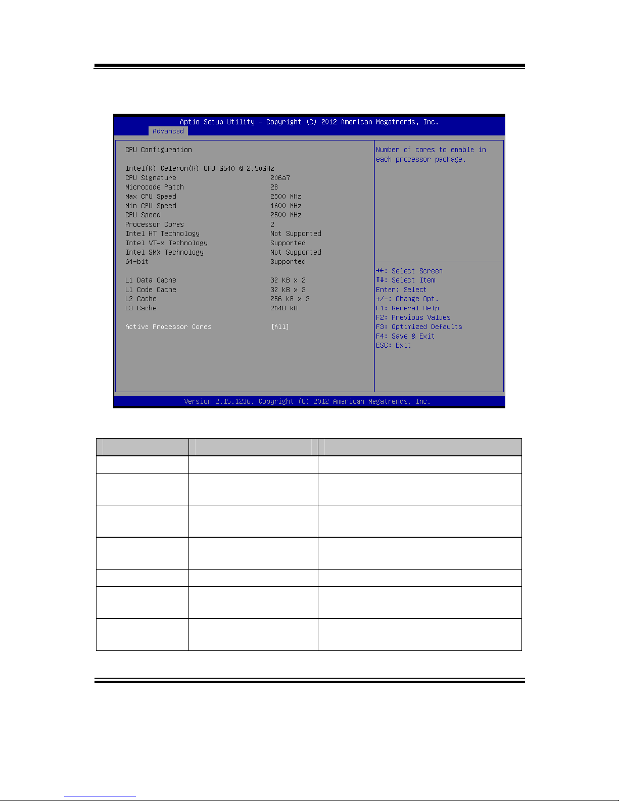
4-4-2. Advanced - CPU Configuration
CPU Configuration screen
BIOS Setting Options Description/Purpose
CPU Signature No changeable options Reports the CPU Signature
Microcode
Patch
No changeable options Reports the CPU Microcode Patch
Version.
Max CPU
Speed
No changeable options Reports the maximum CPU Speed.
Min CPU
Speed
No changeable options Reports the minimum CPU Speed
CPU Speed No changeable options Reports the current CPU Speed
Processor
Cores
No changeable options Displays number of physical cores in
processor.
Intel HT
Technology
No changeable options Reports if Intel Hyper-Threading
Technology is supported by processor
Page 64

Chapter 4 AMI BIOS Setup
PA-6970 SERIES USER′S MANUAL
Page: 4-12
BIOS Setting Options Description/Purpose
Intel VT-x
Technology
No changeable options Reports if Intel VT-x Technology is
supported by processor.
Intel SMX
Technology
No changeable options Reports if Intel SMX Technology is
supported by processor.
64-bit No changeable options Reports if 64-bit is supported by
processor.
L1 Data Cache No changeable options Displays size of L1 Data Cache
L1 Code Cache No changeable options Displays size of L1 Code Cache
L2 Cache No changeable options Displays size of L2 Cache.
L3 Cache No changeable options Displays size of L3 Cache.
Active
Processor
Cores
- All
- 1/2/3…
Choose the number of cores to be
enabled in current processor.
Page 65

Chapter 4 AMI BIOS Setup
PA-6970 SERIES USER′S MANUAL
Page: 4-13
4-4-3. Advanced - SATA Configuration
SATA Configuration screen
BIOS Setting Options Description/Purpose
SATA Controller(s) - Disabled
- Enabled
Enable or disable SATA Device.
SATA Mode
Selection
No changeable
options
Configures SATA as following:
IDE: Set SATA operation mode to
IDE mode.
IDE Legacy / Native
Mode Selection
- Native
- Legacy
Select IDE operation mode as Naïve
mode or Legacy mode.
SATA0 [drive] Displays the drive installed on this
SATA port 0. Shows [Empty] if no
drive is installed.
SATA1 [drive] Displays the drive installed on this
SATA port 1. Shows [Empty] if no
drive is installed.
Page 66

Chapter 4 AMI BIOS Setup
PA-6970 SERIES USER′S MANUAL
Page: 4-14
4-4-4. Advanced - USB Configuration
USB configuration screen
BIOS Setting Options Description/Purpose
USB Devices No changeable options Displays number of available USB
devices.
Legacy USB
Support
- Disabled
- Enabled
- Auto
Enables support for legacy USB.
EHCI Hand-off - Disabled
- Enabled
This is a workaround for OSes w/o
EHCI hand-off support.
Page 67

Chapter 4 AMI BIOS Setup
PA-6970 SERIES USER′S MANUAL
Page: 4-15
4-4-5. Advanced - W83627UHG Super IO Configuration
W83627UHG Super IO configuration screen
BIOS Setting Options Description/Purpose
Super IO Chip No changeable
options
Displays the super IO chip model and
its manufacturer.
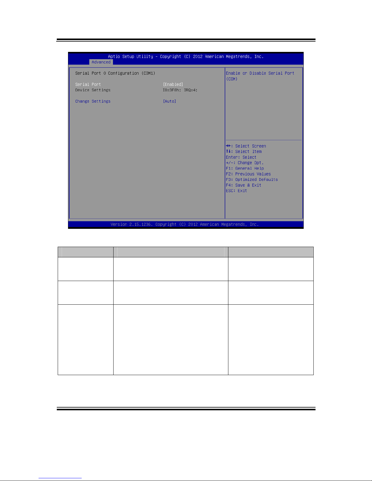
Serial Port 0
Configuration (COM1)
Sub-menu Set Parameters of Serial Port 0
(COM1)
Serial Port 1
Configuration (COM2)
Sub-menu Set Parameters of Serial Port 1
(COM2)
Serial Port 2
Configuration (COM3)
Sub-menu Set Parameters of Serial Port 2
(COM3)
Serial Port 3
Configuration (COM4)
Sub-menu Set Parameters of Serial Port 3
(COM4)
Parallel Port
Configuration
Sub-menu Set Parameters for LPT port.
Page 68
Chapter 4 AMI BIOS Setup
PA-6970 SERIES USER′S MANUAL
Page: 4-16
Serial Port 0 Configuration screen
BIOS Setting Options Description/Purpose
Serial Port - Disabled
- Enabled
Enable or disable COM
1.
Device Settings No changeable options Displays current settings
of COM 1.
Change
Settings
- Auto
- IO=3F8h; IRQ=4
- IO=3F8h; IRQ=3,4,5,6,7,10,11,12
- IO=2F8h; IRQ=3,4,5,6,7,10,11,12
- IO=3E8h; IRQ=3,4,5,6,7,10,11,12
- IO=2E8h; IRQ=3,4,5,6,7,10,11,12
Select IRQ and I/O
resource for the COM 1.
Page 69

Chapter 4 AMI BIOS Setup
PA-6970 SERIES USER′S MANUAL
Page: 4-17
Serial Port 1 Configuration screen
BIOS Setting Options Description/Purpose
Serial Port - Disabled
- Enabled
Enable or disable COM
2.
Device Settings No changeable options Displays current settings
of COM 2.
Change
Settings
- Auto
- IO=2F8h; IRQ=3
- IO=3F8h; IRQ=3,4,5,6,7,10,11,12
- IO=2F8h; IRQ=3,4,5,6,7,10,11,12
- IO=3E8h; IRQ=3,4,5,6,7,10,11,12
- IO=2E8h; IRQ=3,4,5,6,7,10,11,12
Select IRQ and I/O
resource for the COM 2.
Page 70

Chapter 4 AMI BIOS Setup
PA-6970 SERIES USER′S MANUAL
Page: 4-18
Serial Port 2 Configuration screen
BIOS Setting Options Description/Purpose
Serial Port - Disabled
- Enabled
Enable or disable COM
3.
Device Settings No changeable options Displays current settings
of COM 3.
Change
Settings
- Auto
- IO=3E8h; IRQ=3
- IO=3F8h; IRQ=3,4,5,6,7,10,11,12
- IO=2F8h; IRQ=3,4,5,6,7,10,11,12
- IO=3E8h; IRQ=3,4,5,6,7,10,11,12
- IO=2E8h; IRQ=3,4,5,6,7,10,11,12
Select IRQ and I/O
resource for the COM 3.
Page 71

Chapter 4 AMI BIOS Setup
PA-6970 SERIES USER′S MANUAL
Page: 4-19
Serial Port 3 Configuration screen
BIOS Setting Options Description/Purpose
Serial Port - Disabled
- Enabled
Enable or disable COM
4.
Device Settings No changeable options Displays current settings
of COM 4.
Change
Settings
- Auto
- IO=2E8h; IRQ=3
- IO=3F8h; IRQ=3,4,5,6,7,10,11,12
- IO=2F8h; IRQ=3,4,5,6,7,10,11,12
- IO=3E8h; IRQ=3,4,5,6,7,10,11,12
- IO=2E8h; IRQ=3,4,5,6,7,10,11,12
Select IRQ and I/O
resource for the COM 4.
Page 72

Chapter 4 AMI BIOS Setup
PA-6970 SERIES USER′S MANUAL
Page: 4-20
Parallel Port Configuration screen
BIOS Setting Options Description/Purpose
Parallel Port - Disabled
- Enabled
Enable or disable the printer
port.
Device Settings No changeable options Displays current settings of
the printer port.
Change
Settings
- Auto
- IO=378h; IRQ=5
- IO=378h; IRQ=5,6,7,10,11,12
- IO=278h; IRQ=5,6,7,10,11,12
- IO=3BCh; IRQ=5,6,7,10,11,12
Select IRQ and I/O resource
for the printer port..
Page 73

Chapter 4 AMI BIOS Setup
PA-6970 SERIES USER′S MANUAL
Page: 4-21
BIOS Setting Options Description/Purpose
Device Mode - STD Printer Mode
- SPP Mode
- EPP-1.9 and SPP Mode
- EPP-1.7 and SPP Mode
- ECP Mode
- ECP and EPP 1.9 Mode
- ECP and EPP 1.7 Mode
Selects the mode for the
parallel port. Not available
if the parallel port is
disabled.
SPP is Standard Parallel
Port mode, a bidirectional mode for
printers.
EPP is Enhanced Parallel
Port mode, a high-speed
bi-directional mode for
non-printer peripherals.
ECP is Enhanced
Capability Port mode, a
high-speed bi-directional
mode for printers and
scanners.
Page 74
Chapter 4 AMI BIOS Setup
PA-6970 SERIES USER′S MANUAL
Page: 4-22
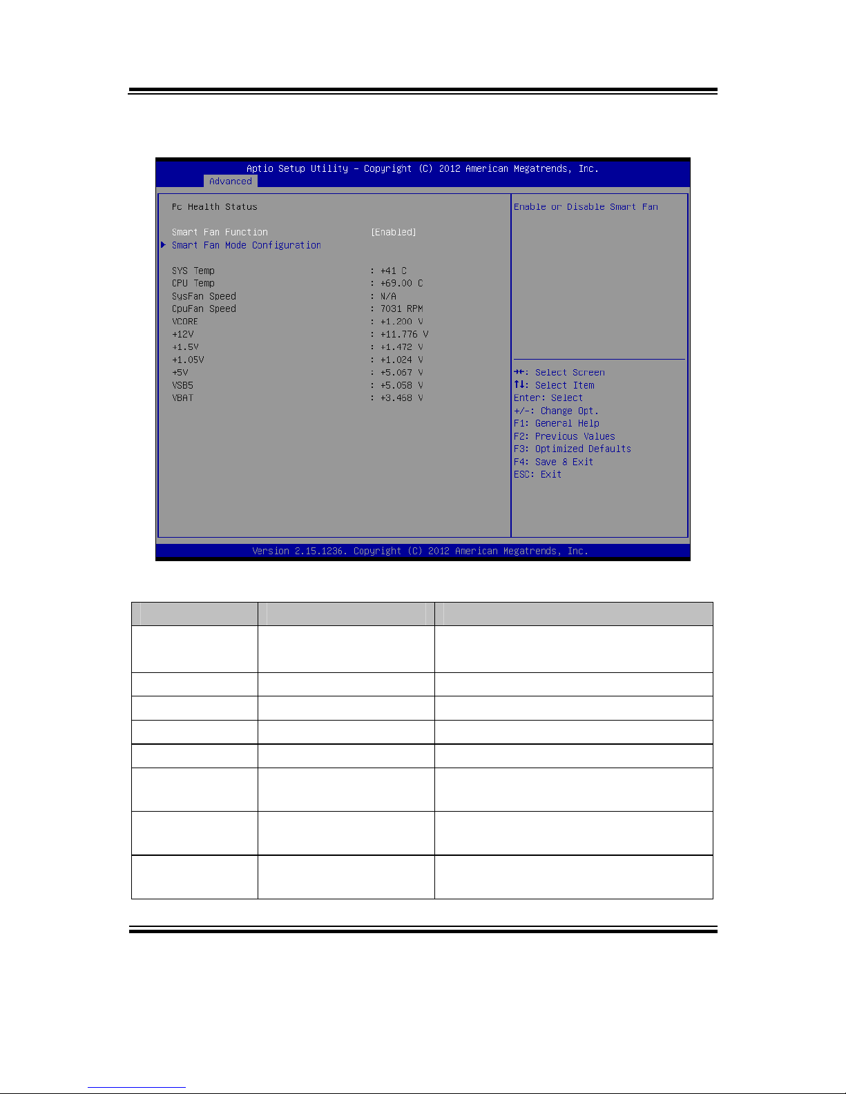
4-4-6. Advanced - W83627UHG H/W Monitor
W83627UHG H/W Monitor screen
BIOS Setting Options Description/Purpose
Smart Fan
Function
- Disabled
- Enabled
Enable smart fan feature.
SYS Temp No changeable options Displays system's temperature.
CPU Temp No changeable options Displays processor's temperature.
SysFan Speed No changeable options Displays fan speed of the System fan.
CpuFan Speed No changeable options Displays fan speed of the CPU fan.
VCORE No changeable options Displays voltage level of the
+VCORE in supply.
+12V No changeable options Displays voltage level of the +12V in
supply.
+1.5V No changeable options Displays voltage level of the +1.5V in
supply.
Page 75

Chapter 4 AMI BIOS Setup
PA-6970 SERIES USER′S MANUAL
Page: 4-23
BIOS Setting Options Description/Purpose
+1.05V No changeable options Displays voltage level of the +1.05V
in supply.
+5V No changeable options Displays voltage level of the +5V in
supply.
VSB5 No changeable options Displays voltage level of the +5VSB
in supply.
VBAT No changeable options Displays voltage level of the backup
CMOS battery.
Page 76

Chapter 4 AMI BIOS Setup
PA-6970 SERIES USER′S MANUAL
Page: 4-24
4-4-6-1. W83627UHG H/W Monitor – Smart Fan Mode Configuration
Smart Fan Mode Configuration screen
BIOS Setting Options Description/Purpose
System fan
mode
- Manual Mode
- Thermal CruiseTM
Mode
Configures the smart fan.
System fan
PWM output
duty
Multiple options
ranging from 0 to 255
CPU Fan PWM output duty
CPU fan mode - Manual Mode
- Thermal CruiseTM
Mode
Configures the smart fan.
CPU fan PWM
output duty
Multiple options
ranging from 0 to 255
CPU Fan PWM output duty
Page 77
Chapter 4 AMI BIOS Setup
PA-6970 SERIES USER′S MANUAL
Page: 4-25
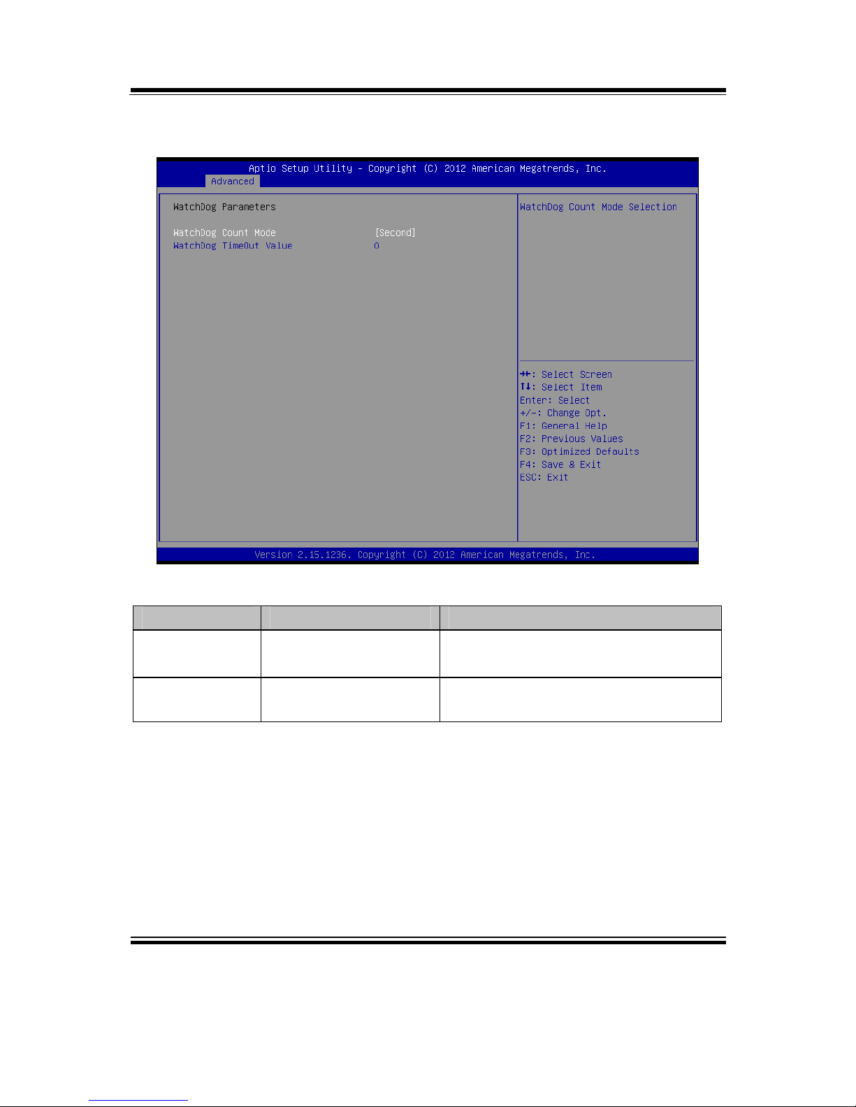
4-4-7. Advanced - Watchdog Configuration
Watchdog configuration screen
BIOS Setting Options Description/Purpose
Watchdog
count mode
- Second
- Minute
Selects unit for watchdog timer.
Watchdog
timeout value
Multiple options
ranging from 0 to 255
Sets the desired value for watchdog
timer. 0 means disabled.
Page 78
Chapter 4 AMI BIOS Setup
PA-6970 SERIES USER′S MANUAL
Page: 4-26
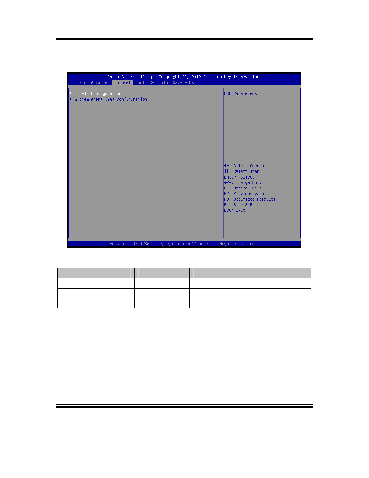
4-5. CHIPSET
Chipset screen
BIOS Setting Options Description/Purpose
PCH-IO Configuration Sub-menu PCH Parameters.
System Agent (SA)
Configuration
Sub-menu System Agent (SA) Parameters.
Page 79
Chapter 4 AMI BIOS Setup
PA-6970 SERIES USER′S MANUAL
Page: 4-27
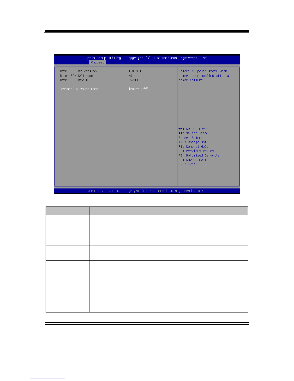
4-5-1. Chipset – PCH IO Configuration
PCH IO Configuration screen
BIOS Setting Options Description/Purpose
Intel PCH RC
Version
No changeable option Displays the PCH source code module
version
Intel PCH SKU
Name
No changeable option Displays PCH product SKU name.
Intel PCH Rev
ID
No changeable option Displays onboard PCH chip revision.
Restore AC
Power Loss
- Power Off
- Power On
Select AC power state when power is
re-applied after a power failure.
Power Off keeps the power off till
the power button is pressed.
Power On makes system power on
after restores AC power to the
board.
Page 80

Chapter 4 AMI BIOS Setup
PA-6970 SERIES USER′S MANUAL
Page: 4-28
4-5-2. Chipset – System Agent (SA) Configuration
System Agent (SA) Configuration screen
BIOS Setting Options Description/Purpose
System Agent
Bridge Name
No changeable options Displays the CPU/NB bridge name
System Agent
RC Version
No changeable options Displays the IVB source code module
version
VT-d
Capability
No changeable options Display this chipset support VT-d or
not.
Graphics
Configuration
Sub-menu Configure Graphic Settings.
Memory
Configuration
Sub-menu Memory Configuration Parameters
Page 81

Chapter 4 AMI BIOS Setup
PA-6970 SERIES USER′S MANUAL
Page: 4-29
Graphics Configuration screen
BIOS Setting Options Description/Purpose
IGFX VBIOS
Version
No changeable options Displays the VBIOS version of
integrated graphic controller.
IGfx Frequency No changeable options Displays the frequency of integrated
graphic controller.
LCD Control Sub-menu LCD Control Parameters.
Page 82
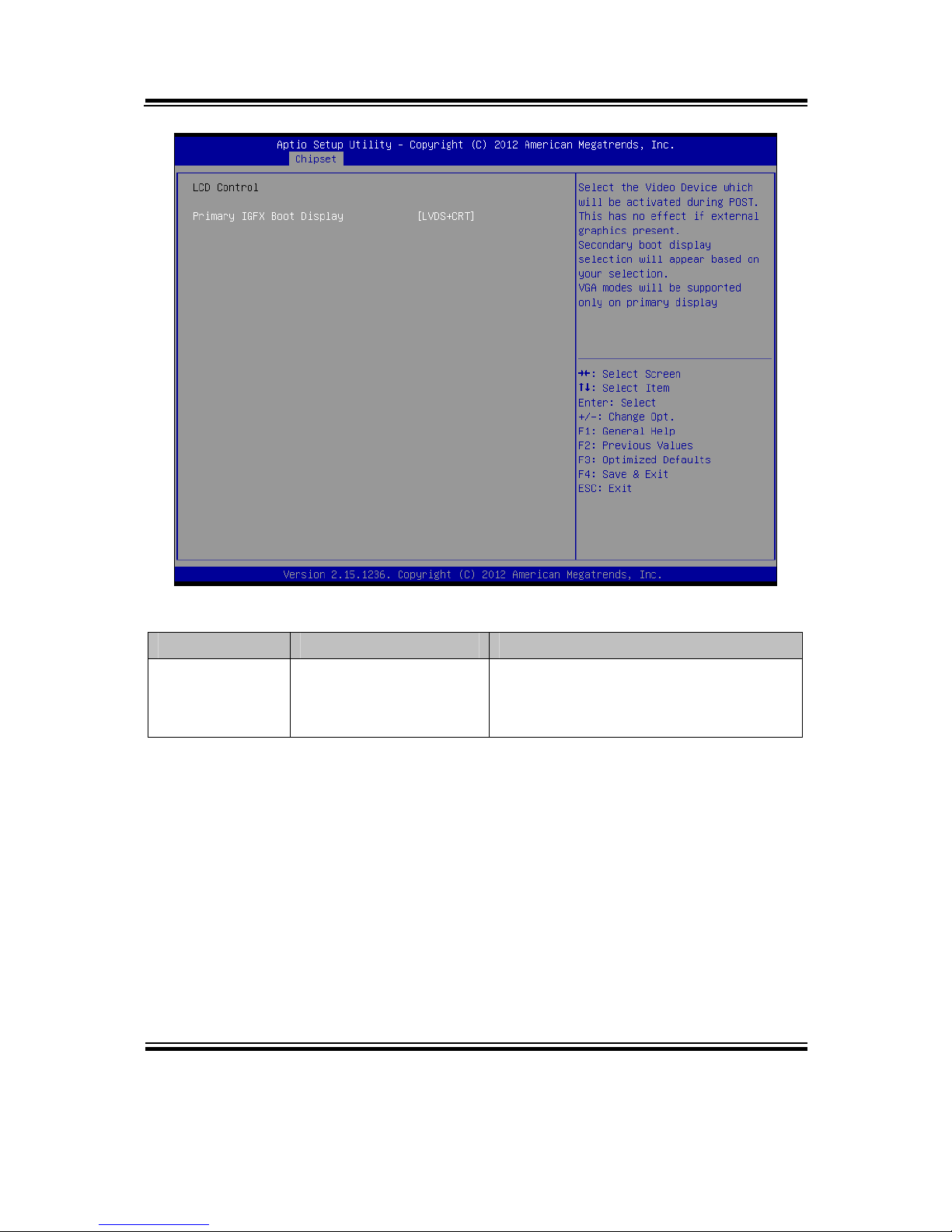
Chapter 4 AMI BIOS Setup
PA-6970 SERIES USER′S MANUAL
Page: 4-30
LCD Control screen
BIOS Setting Options Description/Purpose
Primary IGFX
Boot Display
- LVDS + CRT
- CRT
- LVDS
Select primary display device
Page 83

Chapter 4 AMI BIOS Setup
PA-6970 SERIES USER′S MANUAL
Page: 4-31
Memory Configuration screen
BIOS Setting Options Description/Purpose
Memory
Information
No changeable option
lists.
Displays the detail DRAM
information on platform.
Page 84
Chapter 4 AMI BIOS Setup
PA-6970 SERIES USER′S MANUAL
Page: 4-32
4-6. BOOT
Boot screen
BIOS Setting Options Description/Purpose
Setup Prompt
Timeout
Numeric Number of seconds to wait for setup
activation key.
Bootup
NumLock State
- On
- Off
Specifies the power-on state of the
NumLock Key.
Quiet Boot - Disabled
- Enabled
Enable/Disable Quiet Boot Options
Boot Option
#1~#n
- [Drive(s)]
- Disabled
Allows setting boot option listed in
Hard Drive BBS Priorities.
Hard Drive
BBS Priorities
Sub-Menu Allow user to select boot order of
available drive(s)
CSM
parameters
Sub-Menu Configure Option ROM execution,
boot options filters, etc.
Page 85

Chapter 4 AMI BIOS Setup
PA-6970 SERIES USER′S MANUAL
Page: 4-33
4-7. SECURITY
Security screen
BIOS Setting Options Description/Purpose
Administrator
Password
Password can be 3-20
alphanumeric
characters.
Specifies the administrator password.
User Password Password can be 3-20
alphanumeric
characters.
Specifies the user password.
Page 86

Chapter 4 AMI BIOS Setup
PA-6970 SERIES USER′S MANUAL
Page: 4-34
4-8. SAVE & EXIT
Save & Exit screen
BIOS Setting Options Description/Purpose
Save Changes
and Exit
No changeable options Exits and saves the changes in CMOS
SRAM.
Discard
Changes and
Exit
No changeable options Exits without saving any changes
made in BIOS settings.
Save Changes
and Reset
No changeable options Saves the changes in CMOS SRAM
and resets.
Discard
Changes and
Reset
No changeable options Resets without saving any changes
made in BIOS settings.
Save Changes No changeable options Saves the changes done in BIOS
settings so far.
Page 87

Chapter 4 AMI BIOS Setup
PA-6970 SERIES USER′S MANUAL
Page: 4-35
BIOS Setting Options Description/Purpose
Discard
Changes
No changeable options Discards the changes done in BIOS
settings so far.
Restore
Defaults
No changeable options Loads the optimized defaults for
BIOS settings.
Save as User
Defaults
No changeable options Saves the current values as user
defaults.
Restore User
Defaults
No changeable options Loads the user defaults for BIOS
settings.
Boot Override - [drive(s)] Forces to boot from selected
[drive(s)].
Page 88

Page: A-1
SYSTEM
ASSEMBLY
This appendix contains exploded diagrams and part numbers of the PA6970 system.
Sections included:
Exploded Diagram for PA-6970 Open & Close
Exploded Diagram for PA-6970 Stand
Exploded Diagram for PA-6970 LCD Holder
Exploded Diagram for PA-6970 LCD Disassembly
Exploded Diagram for PA-6970 LCD Panel
Exploded Diagram for PA-6970 Inside Cover
Exploded Diagram for PA-6970 Main Board
Exploded Diagram for PA-6970 Inverter Board
Exploded Diagram for PA-6970 HDD Module
Exploded Diagram for PA-6970 RFID Module
Exploded Diagram for PA-6970 MSR Module
APPENDIX
A
Page 89

Appendix A System Assembly
PA-6970 SERIES USER′S MANUAL
Page: A-2
Exploded Diagram for PA-6970 2nd Display
Exploded Diagram for PA-6970 VFD Module
Page 90

Appendix A System Assembly
PA-6970 SERIES USER′S MANUAL
Page: A-3
EXPLODED DIAGRAM FOR PA-6970 OPEN & CLOSE
01
02
03
04
05
Page 91
Appendix A System Assembly
PA-6970 SERIES USER′S MANUAL
Page: A-4
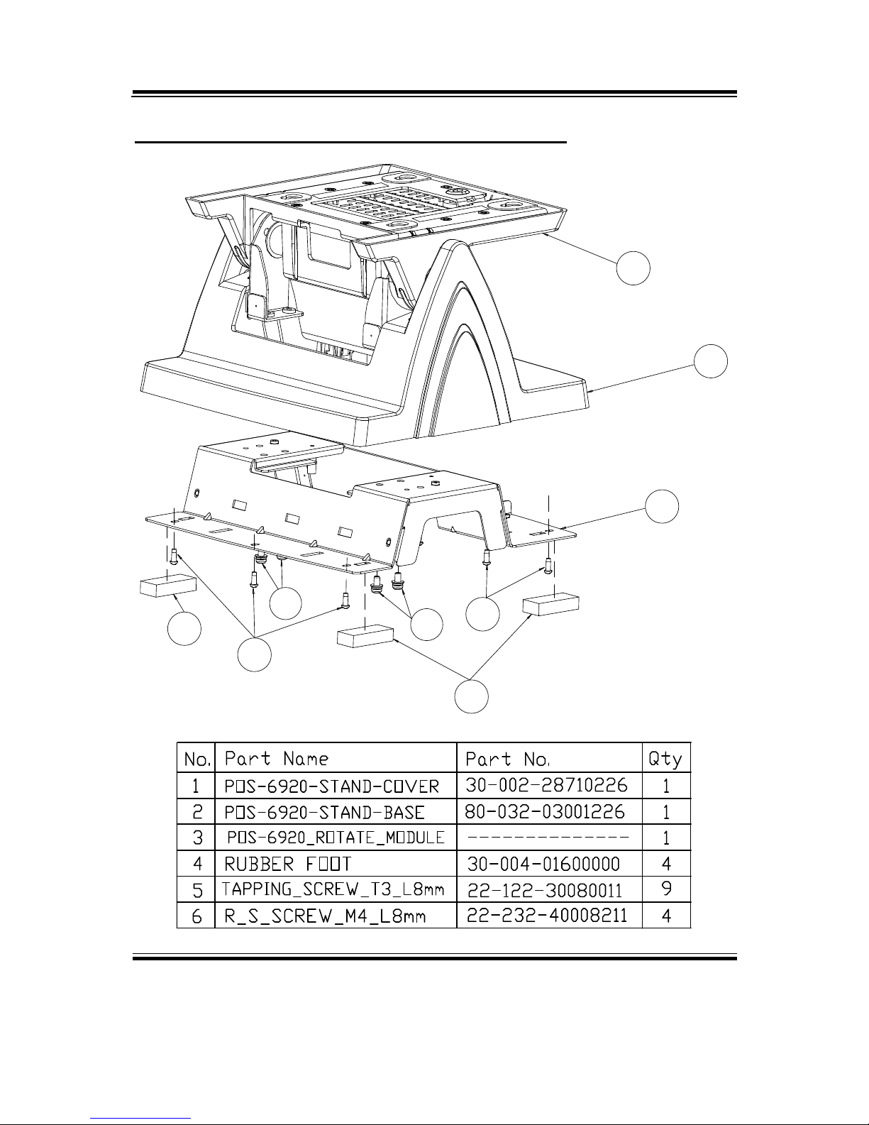
EXPLODED DIAGRAM FOR PA-6970 STAND
01
02
03
04
04
05
05
06
06
Page 92

Appendix A System Assembly
PA-6970 SERIES USER′S MANUAL
Page: A-5
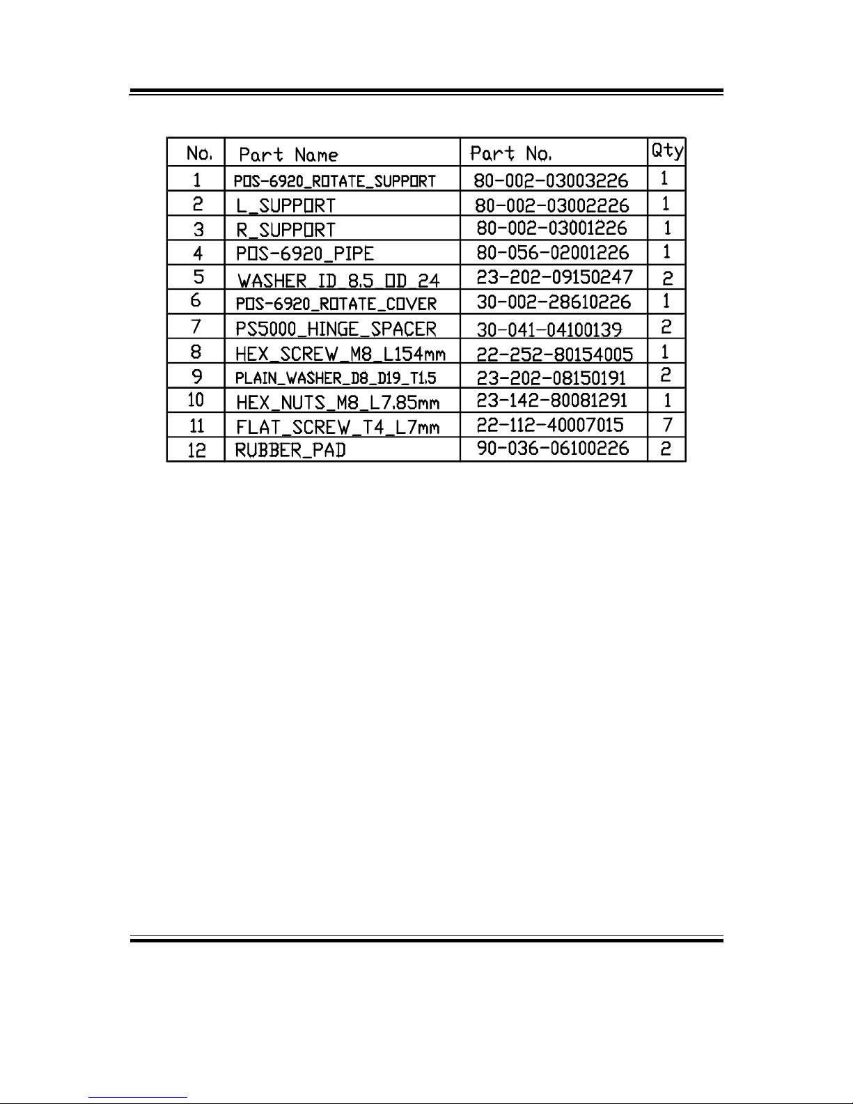
EXPLODED DIAGRAM FOR PA-6970 LCD HOLDER
01
02
03
04
05
06
07
07
08
09
09
10
11
11
12
Page 93
Appendix A System Assembly
PA-6970 SERIES USER′S MANUAL
Page: A-6
Page 94

Appendix A System Assembly
PA-6970 SERIES USER′S MANUAL
Page: A-7
EXPLODED DIAGRAM FOR PA-6970 LCD DISASSEMBLY
01
02
03
04
06
07
05
11
08
10
12
09
09
09
09
Page 95
Appendix A System Assembly
PA-6970 SERIES USER′S MANUAL
Page: A-8
Page 96

Appendix A System Assembly
PA-6970 SERIES USER′S MANUAL
Page: A-9
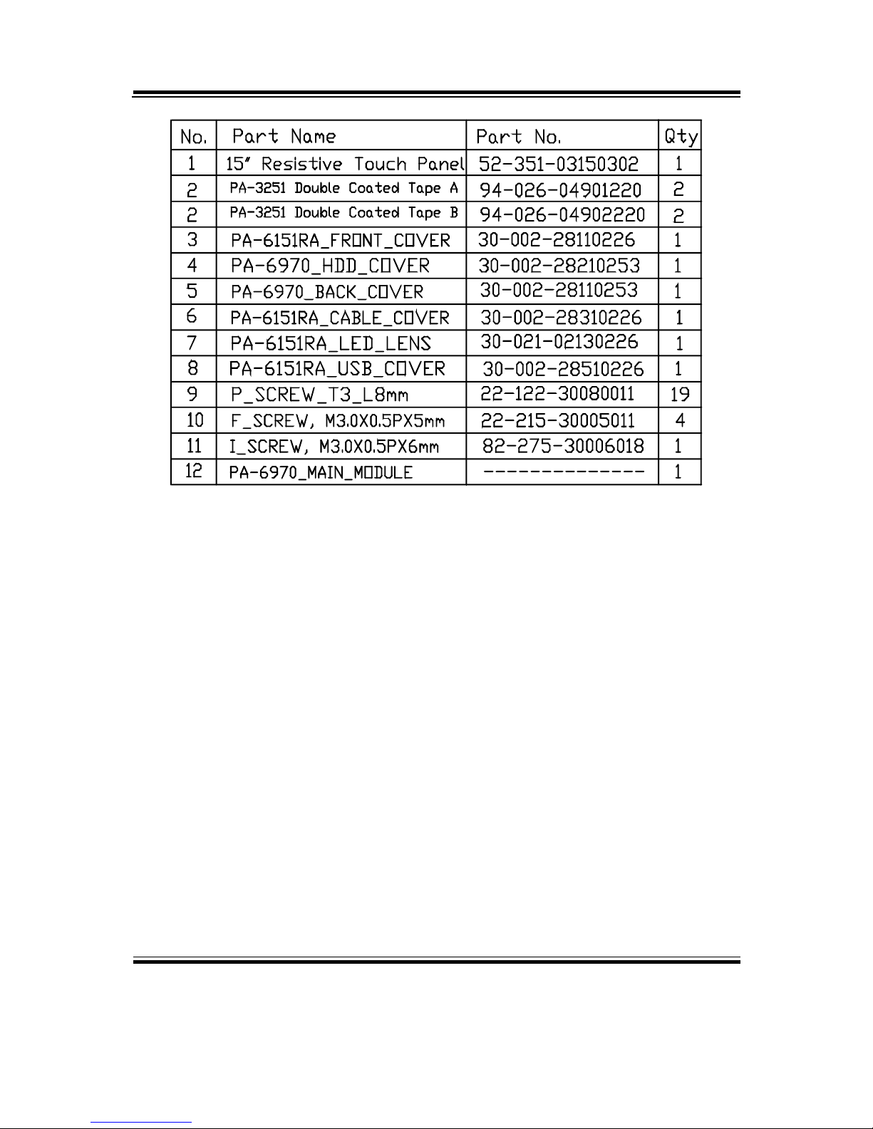
EXPLODED DIAGRAM FOR PA-6970 LCD PANEL
01
01
01
01
02
03
04
05
11
12
21
22
13
14
15
06
08
09
10
16
17
17
17
17
19
20
07
18
Page 97

Appendix A System Assembly
PA-6970 SERIES USER′S MANUAL
Page: A-10
Page 98

Appendix A System Assembly
PA-6970 SERIES USER′S MANUAL
Page: A-11
EXPLODED DIAGRAM FOR PA-6970 INSIDE COVER
01
02
03
04
06
06
07
05
Page 99

Appendix A System Assembly
PA-6970 SERIES USER′S MANUAL
Page: A-12
EXPLODED DIAGRAM FOR PA-6970 MAIN BOARD
01
02
03
04
05
11
11
06
08
07
09
10
Page 100

Appendix A System Assembly
PA-6970 SERIES USER′S MANUAL
Page: A-13
 Loading...