

Page 1
®
PROTECH
1/05
INSTALLATION & OPERATION
MANUAL
MX411 VOICE ACTIVATED RELAY
WWW.PROTECHAUDIO.COM
All Quicktrack products use a consistent ground scheme. The MXT-1 power supply provides the
necessary ground conductor. Power supplies without the 3rd conductor ground should not be used
with Quicktrack products.
CAUTION: Do not plug power supply into AC receptacle until the secondary conductors have been
attached to the Quicktrack module. Doing so may cause the power supply conductors to short and
damage the supply.
Installion steps for the Quicktrack modules are as follows;
1- Remove the cover screw (All modules except MX410) and cover.
2- Press down on the lower edge of the Quicktrack mounting extrusion until the lower edge of the
printed circuit assembly comes free.
3- Slip the printed circuit assembly out of the upper edge of the mounting extrusion.
4- Mount the Quicktrack mounting extrusion in an appropriate location, away from moisture, heat
sources, and AC fields.
5- Connect all audio connections to the barrier connector using double conductor shielded cables
designed for low level audio signals. Do not use multiple solid conductor cables.
6- Connect the 3 power supply conductors to the power supply connection points on the barrier
connector.
7- Plug the power supply into an AC receptacled.
8- Check for proper illumination of the LED power indicator.
9- Adjust all audio levels as necessary.
10- Mount the cover onto the Quicktrack module being careful not to over-tighten the mounting
screw.
Phantom
1
2
25/70V PAD
Relay Controls Threshold and
Dropout Delay
All initial adjustments on the MX411 are made at the factory. If after installing the unit higher or lower output
levels are desired follow the these steps.
Adjust audio levels for desired output before adjusting.
Next adjust threshold and delay trimpots for desired triggering and dropout delay.
Protech Audio Corporation, PO Box 597, 192 Cedar River Road, Indian Lake, New York, 12842, Voice 518-648-6410 Fax 518-648-6395
+15V
M
L
MODEL MX411
S
L
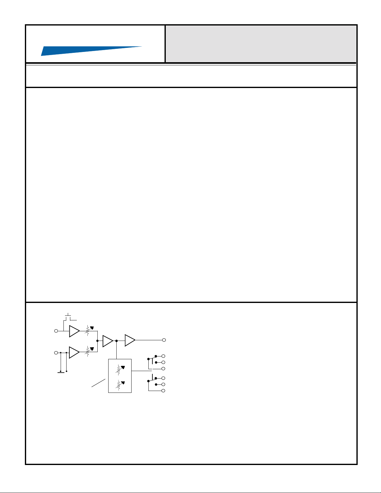
The Model MX411 has one mic input, and one line input,
mixed to a common signal, and sent to the output. Both
inputs have adjustable gain. The mic input has a pushon jumper for internal 15 volt phantom power. The line
input has a switchable pad to allow either st andard line
level signals (0dBv Ref.), or 25/70 Volt signals.
The threshold and the dropout delay for the relay are
adjustable. Audio signals entering either input can be
used to activate the relay.
Both inputs and the output are electronically balanced.
The output may be used in either a balanced or
unbalanced configuration. Requires low voltage AC power
(See MXT-1).
Page 2
PROTECH
WWW.PROTECHAUDIO.COM
®
9/02
INSTALLATION & OPERATION
MANUAL
MX411 VOICE ACTIVATED RELAY
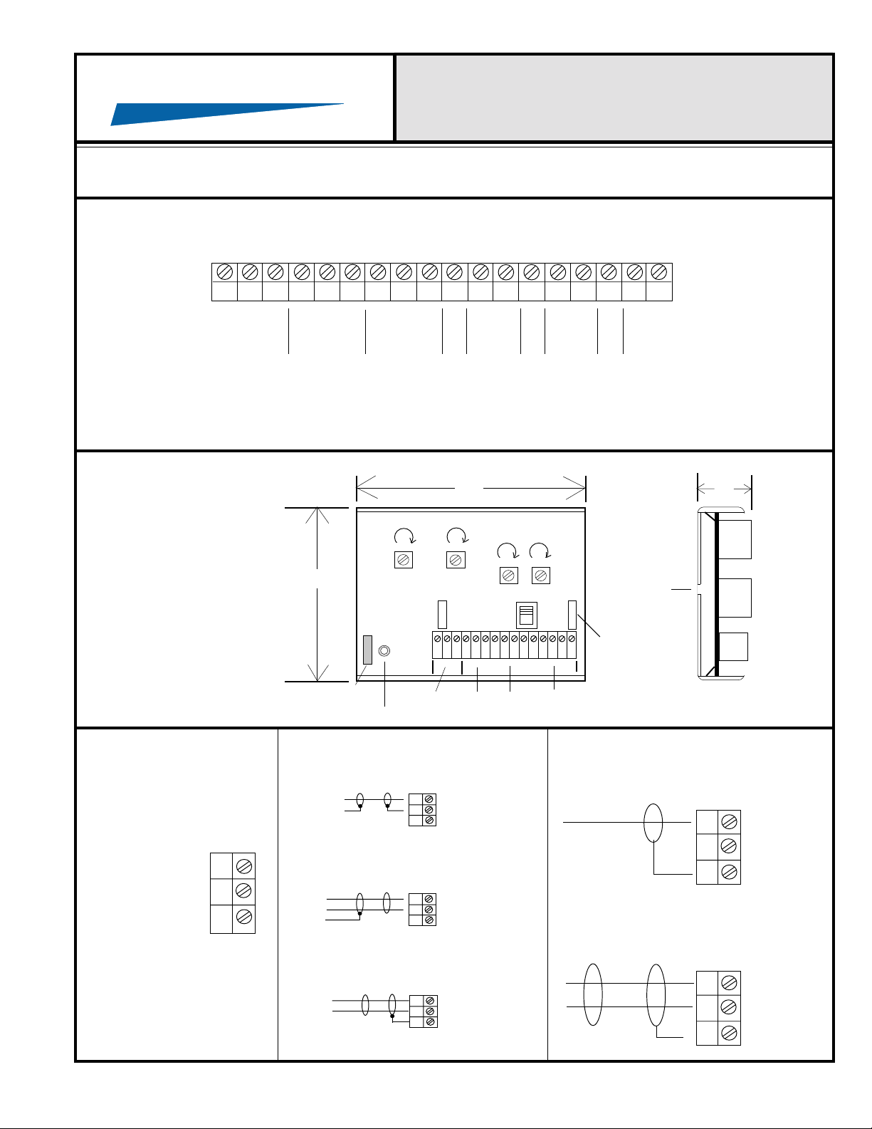
18
VAC
ALL
QUICKTRACK
PRODUCTS
USE
CONSISTENT
GROUNDING
SCHEMES
AND
PACKAGING
18
VAC
G
N
NO COM NC
D
RELAY
NO COM NC
CONNECTIONS
3.375"
FUSE
POWER ON INDICATOR
RELAY
LONGER
DELAY
GROUND LIFT
POWER RELAY OUTPUT INPUTS
LINE OUT
N
C
4.5"
LOWER
THRESHOLD
PAD
N
C
MORE
IN
OUT
- +
GAIN ADJUSTMENTS
LINE IN
- +
MIC IN
N
C
MOUNTING
HOLES
PHANTOM
POWER
- +
1.0"
POWER FROM
MXT
TRANSFORMER
RED - AC
BLACK - AC
GREEN - (GND)
UNBALANCED LINE INPUT
CONNECTION
HI
LO
SH
BALANCED LINE INPUT
CONNECTION
HI
LO
SH
UNBALANCED LINE OUTPUT
CONNECTION
HI
LO
SH
BALANCED LINE OUTPUT
CONNECTION
MICROPHONE INPUT
CONNECTION
HI
LO
SH
HI
LO
SH
Protech Audio Corporation, PO Box 597, 192 Cedar River Road, Indian Lake, New York, 12842, Voice 518-648-6410 Fax 518-648-6395
Page 3

PROTECH
Paging
Mic
®
Juke Box and Page Automatically Override Radio.
MODEL MX411
Model MX411
Audio Activated Relay Module
Radio
1
2
Juke
Box
M
L
Gain
Adjustments
S
Control
L
Speaker(s)
Relay
Power
Amp
When patrons play the juke box, the MX411 automatically switches from the radio to the juke
box.
If a page is made, while the radio is playing, the MX411 automatically switches from the radio
to the page signal.
If a page is made while the juke box is playing, the page is heard while the juke box plays.
When the page is over, or the juke box stops playing, the MX411 automatically switches back
to the radio.
The radio is used as an example music source. It could be a cassette or CD player.
This set-up frees restaurant employees from having to do the switching.
WWW.PROTECHAUDIO.COM
Protech Audio Corporation, PO Box 597, 192 Cedar River Road, Indian Lake, New York, 12842, Voice 518-648-6410 Fax 518-648-6395
 Loading...