

Page 1
®
PROTECH
1/05
INSTALLATION & OPERATION
MANUAL
MX405 AUDIO DISTRIBUTION AMPLIFIER, Rev. A
WWW.PROTECHAUDIO.COM
All Quicktrack products use a consistent ground scheme. The MXT-1 power supply provides the
necessary ground conductor. Power supplies without the 3rd conductor ground should not be used
with Quicktrack products.
CAUTION: Do not plug power supply into AC receptacle until the secondary conductors have been
attached to the Quicktrack module. Doing so may cause the power supply conductors to short and
damage the supply.
Installion steps for the Quicktrack modules are as follows;
1- Remove the cover screw (All modules except MX410) and cover.
2- Press down on the lower edge of the Quicktrack mounting extrusion until the lower edge of the
printed circuit assembly comes free.
3- Slip the printed circuit assembly out of the upper edge of the mounting extrusion.
4- Mount the Quicktrack mounting extrusion in an appropriate location, away from moisture, heat
sources, and AC fields.
5- Connect all audio connections to the barrier connector using double conductor shielded cables
designed for low level audio signals. Do not use multiple solid conductor cables.
6- Connect the 3 power supply conductors to the power supply connection points on the barrier
connector.
7- Plug the power supply into an AC receptacled.
8- Check for proper illumination of the LED power indicator.
9- Adjust all audio levels as necessary.
10- Mount the cover onto the Quicktrack module being careful not to over-tighten the mounting
screw.
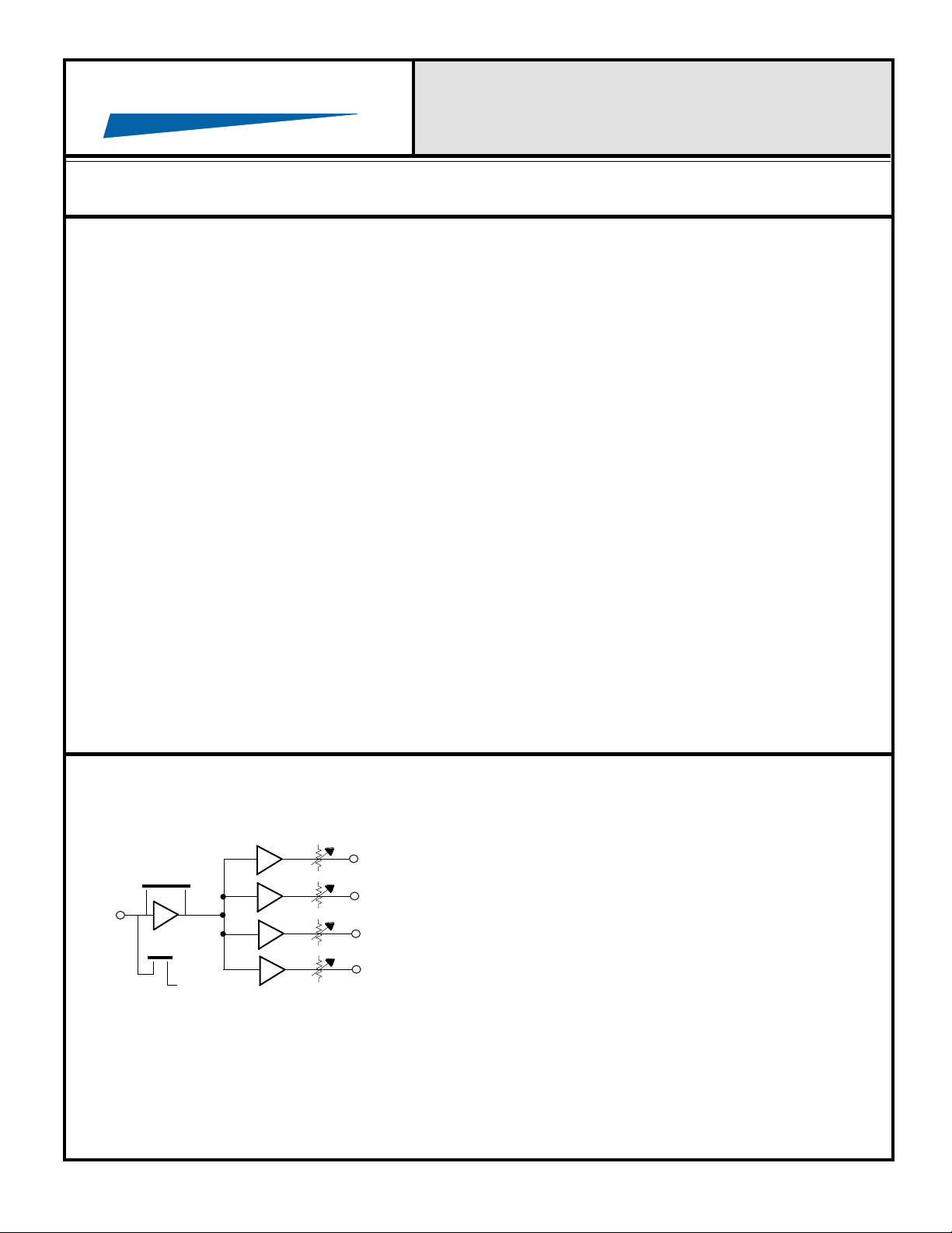
MODEL MX405
The Model MX405 has one microphone input and four line
JP3, Off = +10dB
M
PHANTOM
+15VDC
All initial adjustments on the MX405 are made at the factory. If after installing the unit higher or lower output
levels are desired, adjust outputs using trimpots as indicated.
Protech Audio Corporation, PO Box 597, 192 Cedar River Road, Indian Lake, New York, 12842, Voice 518-648-6410 Fax 518-648-6395
L
L
L
L
1
2
3
4
outputs. The microphone input incorporates a 15 volt phantom
power circuit, which is activated by a push-on jumper. The
input gain can be increased by 10dB by removing push-on
shunt at JP3. The outputs have adjustable gain.
All inputs and the output are electronically balanced. The
outputs may be used in either a balanced or unbalanced
configuration. Requires low voltage AC power (See MXT-1).
Page 2
PROTECH
WWW.PROTECHAUDIO.COM
®
INSTALLATION & OPERATION
MANUAL
MX405 AUDIO DISTRIBUTION AMPLIFIER, Rev. A
ALL
QUICKTRACK
PRODUCTS
USE
CONSISTENT
GROUNDING
SCHEMES
AND
PACKAGING
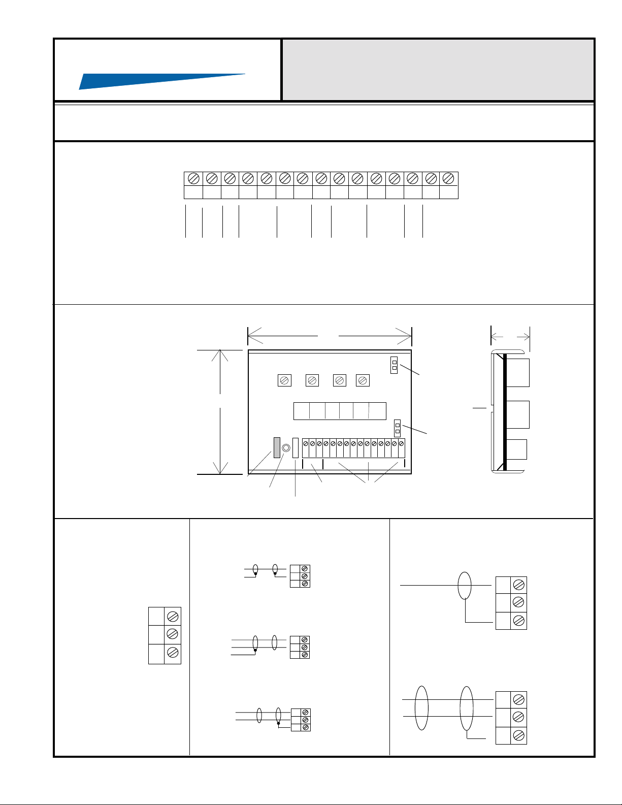
18
VAC18VAC
3.375"
POWER ON INDICATOR
G
OUT #4
N
- +
D
OUT #3
- +
OUT #2
S
- +
H
OUT #1
- +
S
H
INPUT #1
- +
CONNECTIONS
FUSE
POWER INPUTS AND OUTPUTS
GROUND LIFT
4.5"
SOCKETED IC'S
JP3
On = 0dB
Off = +10dB
MOUNTING
HOLES
PHANTOM
POWER
JUMPER
1.0"
POWER FROM
MXT
TRANSFORMER
RED - AC
BLACK - AC
GREEN - (GND)
UNBALANCED LINE
INPUT
CONNECTION
BALANCED LINE INPUT
CONNECTION
HI
LO
SH
HI
LO
SH
UNBALANCED LINE OUTPUT
CONNECTION
HI
LO
SH
BALANCED LINE OUTPUT
CONNECTION
MICROPHONE INPUT
CONNECTION
HI
LO
SH
HI
LO
SH
Protech Audio Corp. 192 Cedar River Road, Indian Lake, New York 12842 Voice 518-648-6410 Fax 518-648-6395
 Loading...