

Page 1

USER
MANUAL
BS-W025
Intel 6th/7th Gen. Core
TM
/
Pentium / Celeron Industrial
Wallmount System with DC
Power Input
BS-W025 M2
Page 2

BS-W025
Intel 6th/7th Gen. Core
TM
/ Pentium /
Celeron® Industrial Wallmount System
with DC Power Input
COPYRIGHT NOTICE & TRADEMARK
All trademarks and registered trademarks mentioned herein are the
property of their respective owners.
This manual is copyrighted in September 2017. You may not
reproduce or transmit in any form or by any means, electronic, or
mechanical, including photocopying and recording.
DISCLAIMER
This user’s manual is meant to assist users in installing and setting up
the system. The information contained in this document is subject to
change without any notice.
CE NOTICE
This is a class A product. In a domestic environment this product may
cause radio interference in which case the user may be required to take
adequate measures.
FCC NOTICE
This equipment has been tested and found to comply with the limits for
a Class A digital device, pursuant to part 15 of the FCC Rules. These
Page 3
limits are designed to provide reasonable protection against harmful
interference when the equipment is operated in a commercial
environment. This equipment generates, uses, and can radiate radio
frequency energy and, if not installed and used in accordance with the
instruction manual, may cause harmful interference to radio
communications. Operation of this equipment in a residential area is
likely to cause harmful interference in which case the user will be
required to correct the interference at his own expense.
You are cautioned that any change or modifications to the equipment
not expressly approve by the party responsible for compliance could
void your authority to operate such equipment.
CAUTION: Danger of explosion may occur when the battery
is incorrectly replaced. Replace the battery only with the
same or equivalent type recommended by the manufacturer.
Dispose of used batteries according to the manufacturer’s
instructions.
WARNING: Some internal parts of the system may have high
electrical voltage. We strongly recommend that only qualified
engineers are allowed to service and disassemble the
system. If any damages should occur on the system and are
caused by unauthorized servicing, it will not be covered by
the product warranty.
Page 4

i
Contents
1 Introduction ......................................................................................... 1-1
1.1 About This Manual .................................................................... 1-2
2 Getting Started .................................................................................... 2-1
2.1 Packing List ............................................................................... 2-2
2.2 System Overview ...................................................................... 2-3
Front View ......................................................................................... 2-3
Rear View.......................................................................................... 2-3
Top View ........................................................................................... 2-4
Side View .......................................................................................... 2-4
Quarter View ..................................................................................... 2-5
2.3 BS-W025 Specifications ............................................................ 2-6
2.4 Safety Precautions .................................................................... 2-8
3 Hardware Configuration ..................................................................... 3-1
3.1 External System I/O Ports Diagrams ........................................ 3-2
Front I/O Ports Diagram .................................................................... 3-2
Rear I/O Ports Diagram .................................................................... 3-2
3.2 Jumper & Connector Quick Reference Table ............................ 3-3
3.3 Component Locations ............................................................... 3-4
3.4 How To Set Jumpers ................................................................. 3-6
3.5 COM Port and Connectors ........................................................ 3-8
3.6 Clear CMOS Data Selection ................................................... 3-10
3.7 COM Port RI / Voltage Selection ............................................. 3-11
3.8 Digital I/O Port Connector ....................................................... 3-12
Page 5

ii
3.9 Keyboard & Mouse Port .......................................................... 3-13
3.10 DVI (Digital Video Interface) Port ............................................ 3-14
3.11 VGA Port ................................................................................. 3-15
3.12 Front Panel Connector ............................................................ 3-16
3.13 LAN & USB Port ...................................................................... 3-17
3.14 Line-in, Line-out, Mic-in Port ................................................... 3-19
3.15 RS-232/422/485 (COM2) Selection ........................................ 3-20
3.16 COM2 Auto Detection Selection.............................................. 3-21
3.17 Hardware Power Failure Selection.......................................... 3-22
3.18 Flash Descriptor Override Selection ....................................... 3-23
3.19 LAN2 Enable / Disable Selection ............................................ 3-24
3.20 Mini PCIE Voltage Selection ................................................... 3-25
3.21 VCCIO Voltage Selection ........................................................ 3-26
3.22 MINI PCI Express Slot ............................................................ 3-27
3.23 PCI Express Slots ................................................................... 3-28
3.24 CPU / System Fan Connectors ............................................... 3-32
3.25 Serial ATA (SATA) Connectors ................................................ 3-33
3.26 Internal USB 3.0 Connector .................................................... 3-34
3.27 Internal USB 2.0 Conncetors .................................................. 3-34
3.28 Display Port Connector ........................................................... 3-35
3.29 Power Input Connectors .......................................................... 3-36
3.30 Speaker Connector ................................................................. 3-37
Page 6

iii
3.31 LPC Connector ........................................................................ 3-37
4 Software Utilities ................................................................................. 4-1
4.1 Introduction ................................................................................ 4-2
4.2 Installing Intel RST Driver Utility (For Q170/C236 SKU) ........... 4-7
4.3 Intel® RapidStorage Technology Option ROM .......................... 4-7
5 BIOS SETUP ........................................................................................ 5-1
5.1 Introduction ................................................................................ 5-2
5.2 Accessing Setup Utility .............................................................. 5-3
5.3 Main ........................................................................................... 5-6
5.4 Advanced .................................................................................. 5-7
Advanced - Trusted Computing ........................................................ 5-8
Advanced - ACPI Settings .............................................................. 5-10
Advanced – PCH-FW Configuration ............................................... 5-11
Advanced – F81866 Super IO Configuration .................................. 5-12
Advanced – Hardware Monitor ....................................................... 5-19
Advanced - Smart Fan Mode Configuration ................................... 5-21
Advanced - F81866 Watchdog Configuration ................................. 5-22
Advanced - CPU Configuration ....................................................... 5-23
Advanced - SATA Configuration (AHCI Mode) ............................... 5-25
Advanced - Network Stack Configuration ....................................... 5-27
Advanced - USB Configuration ....................................................... 5-29
5.5 Chipset .................................................................................... 5-30
Chipset - System Agent (SA) Configuration.................................... 5-31
Chipset - Graphics Configuration .................................................... 5-33
Chipset - SA Configuration > PEG Port Configuration ................... 5-35
Chipset – SA Configuration > Memory Configuration ..................... 5-36
Page 7

iv
Chipset – PCH-IO Configuration ..................................................... 5-37
Chipset - PCI Express Configuration .............................................. 5-38
5.6 Security ................................................................................... 5-47
5.7 Boot ......................................................................................... 5-49
BOOT > CSM Configuration .............................................................. 5-52
5.8 Save & Exit .............................................................................. 5-54
Appendix A System Diagram ...................................................... A-1
BS-W025 System Exploded Diagram ......................................................A-2
Appendix B Technical Summary ................................................ B-1
Block Diagram ..........................................................................................B-2
Interrupt Map ............................................................................................B-3
I/O MAP ..................................................................................................B-17
Memory Map ...........................................................................................B-20
Configuring WatchDog Timer .................................................................B-23
Flash BIOS Update .................................................................................B-25
Page 8

v
Revision History
The revision history of BS-W025 User Manual is described below:
Version No.
Revision History
Date
M1
Initial Release
2017/09/20
M2
• Revised the operating voltage for the power supply
as DC 24V in the Safety Precaution section.
• Modified Chapter 4 Software Utilities.
• Modified Chapter 5 BIOS Setup.
• Modified Appendix B.
• Corrected typos in BS-W025 User Manual.
2017/10/03
Page 9

BS-W025 SERIES USER MANUAL
Page: 1-1
1 Introduction
This chapter provides the introduction for BS-W025 system
as well as the framework of the user manual.
The following topic is included:
• About This Manual
Page 10

Chapter 1 Introduction
BS-W025 SERIES USER MANUAL
Page: 1-2
1.1 About This Manual
Thank you for purchasing our BS-W025 system. The BS-W025 provides faster
processing speed, greater expandability and can handle more tasks than before. This
manual is designed to assist you how to install and set up the whole system. It
contains 5 chapters and 2 appendixes. Users can configure the system according to
their own needs. This user manual is intended for service personnel with strong
hardware background. It is not intended for general users.
The following section outlines the structure of this user manual.
Chapter 1 Introduction
This chapter provides the introduction for the BS-W025 system as well as the
framework of the user manual.
Chapter 2 Getting Started
This chapter describes the package contents and outlines the system specifications.
Read the safety reminders carefully on how to take care of your system properly.
Chapter 3 System Configuration
This chapter describes the external I/O ports, outlines the locations of the
motherboard components and their respective functions. You will learn how to set the
jumpers and configure the system to meet your own needs.
Chapter 4 Software Utilities
This chapter contains helpful information for proper installations of the Intel Chipset
Software Installation Utility, VGA Driver Utility, LAN Driver Utility, RAID Driver
Utility and Sound Driver Utility.
Chapter 5 BIOS Setup
This chapter indicates you how to change the BIOS configurations.
Appendix A System Assembly
This appendix gives you the system exploded diagram and part numbers of the
BS-W025.
Appendix B Technical Summary
This appendix provides the information about the allocation maps for the system
resources, Watchdog Timer Configuration and Flash BIOS Update.
.
Page 11

BS-W025 SERIES USER MANUAL
Page: 2-1
2 Getting Started
This chapter provides the information for the BS-W025
system. It describes the package contents and outlines the
system specifications.
The following topics are included:
• Package List
• System Overview
• System Specification
• Safety Precautions
Experienced users can go to Chapter 3 System
Configuration on page 3-1 for a quick start.
Page 12

Chapter 2 Getting Started
BS-W025 SERIES USER MANUAL
Page: 2-2
2.1 Packing List
If you discover any of the items listed below are damaged or lost,
please contact your local distributor immediately.
Item
Q’ty
BS-W025
1
Quick Reference Guide
1
Manual / Driver DVD
1
Mini Jumper (2.0 mm)
6
Page 13
Chapter 2 Getting Started
BS-W025 SERIES USER MANUAL
Page: 2-3
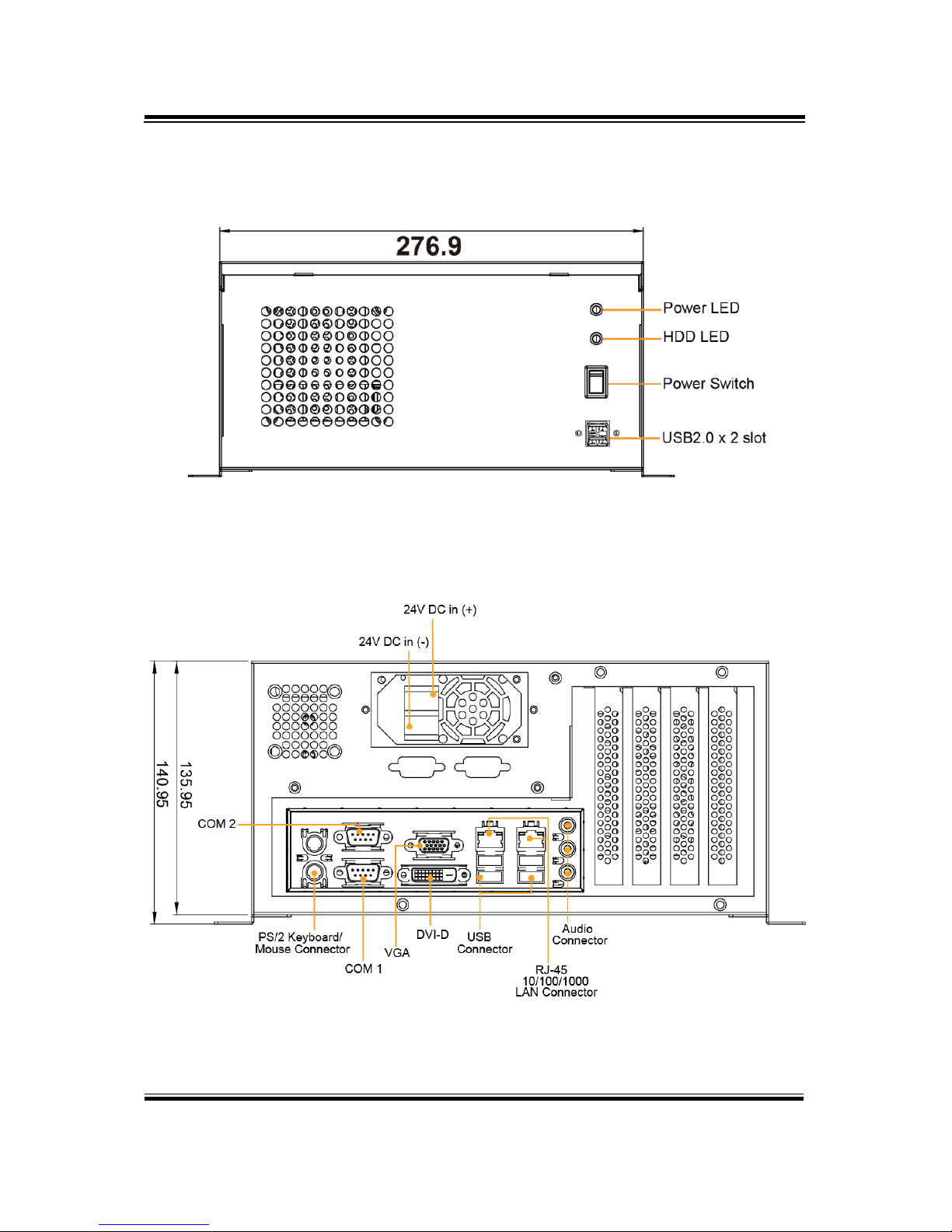
2.2 System Overview
Unit: mm
Front View
Rear View
Page 14
Chapter 2 Getting Started
BS-W025 SERIES USER MANUAL
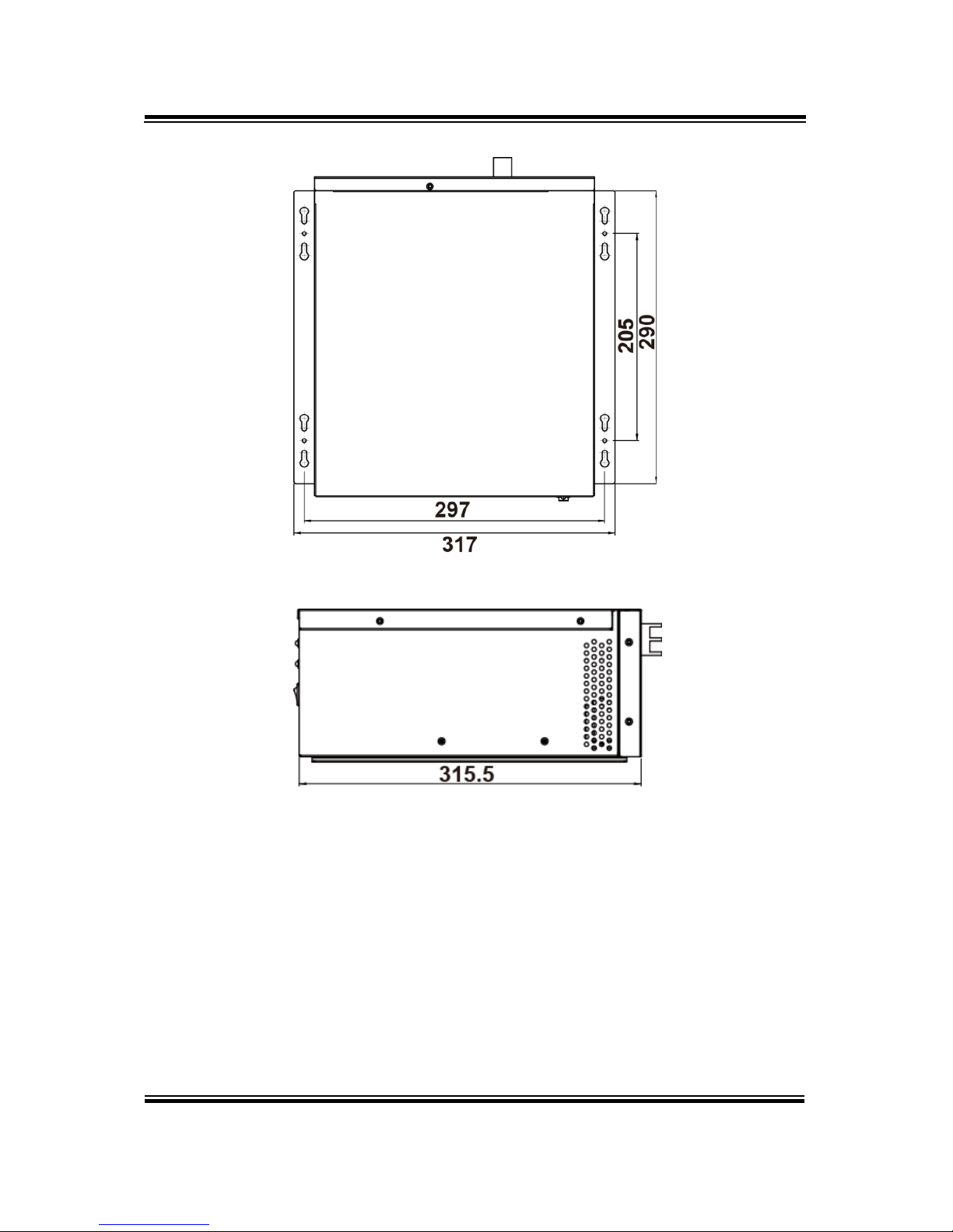
Page: 2-4
Top View
Side View
Page 15
Chapter 2 Getting Started
BS-W025 SERIES USER MANUAL
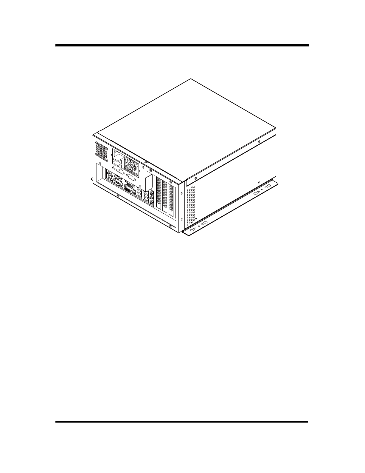
Page: 2-5
Quarter View
Page 16

Chapter 2 Getting Started
BS-W025 SERIES USER MANUAL
Page: 2-6
2.3 BS-W025 Specifications
System
CPU Support
6th/7th Gen. Intel® Core™ i7/i5/i3 & Pentium/Celeron
®
processor
Socket type: LGA 1151
Chipset
Intel® Q170 / H110 / C236
Memory Support
Up to 4 x DDR4 2133MHz UDIMM (H110 SKU only 2
UDIMM)
Drive Bay for Storage
Supports 2 x 2.5” HDD/SSD
Watchdog
1~255 seconds watchdog timer selectable
Power Supply
Supports DC 24V input
System Fan
2 x system fans
Dimension (W x H x D)
277mm(W) x 135.95mm(H) x 315.5mm(D)
Certificate
FCC/CE
OS Support
Windows 10(64) / Windows 8.1(64) /
Windows 7 Pro(32/64)
I/O Ports (Internal)
SATA
6 x SATA3.0 (supports RAID 0/1 in Q170/C236 SKU)
Serial Port
4 x COM (internal)
COM 3-6 for RS232,
COM3/4 supports 5V/12V(selectable by BIOS)
USB
1 x USB2.0 port
Digital IO
8in/8out(onboard wafer)
LPC
1 x LPC pin header (for optional TPM module)
Mini PCIe
1 x mini-PCIe slot
I/O Ports (Front Side)
USB
2 x USB 2.0
Power Switch
1 x Power Switch
I/O Ports (Rear Side)
Display
1 x VGA up to 1920x1200 @60Hz
1 x DVI-D up to 1920x1200@60Hz
Serial Port
2 x COM ports
COM1 for RS232,
COM2 for RS232/422/485 (selectable by BIOS)
USB
4 x USB 3.0
Page 17

Chapter 2 Getting Started
BS-W025 SERIES USER MANUAL
Page: 2-7
Keyboard / Mouse
2 x PS/2 with mini DIN connectors
LAN
2 x GbE LAN, Wake-On-LAN, PXE
LAN 1: Intel® PHY-I219 LM (10/100/1000 Mbps)
LAN 2: Intel® LAN I210 AT (10/100/1000 Mbps)
Audio
1 x Line-in / 1 x Line-out / 1 x Mic-in
Expansion Slot
Q170/C236 SKU: 1 x PCIe (x16), 2 x PCIe (x4),
1 x PCIe (x1)
H110 SKU: 1 x PCIe (x16), 1 x PCIe (x4),1 x PCIe (x1)
Power Input
DC 24V Power Input Connector
Environment
Operating Temp.
0°C ~ 40°C (32°F ~ 104°F) ; Humidity: 20% ~ 90%
Storage Temp.
-20°C ~ 80°C (-4°F ~ 176°F); Humidity: 20% ~ 90%
Note: BS-W025RA-01B uses motherboard BU-2509R*-00N, which uses PCH Q170.
Page 18

Chapter 2 Getting Started
BS-W025 SERIES USER MANUAL
Page: 2-8
2.4 Safety Precautions
Before operating this system, read the following information carefully to protect your
systems from damages, and extend the life cycle of the system.
1. Check the Line Voltage
• The operating voltage for the power supply should be DC 24V; otherwise
the system may be damaged.
2. Environmental Conditions
• Place your BS-W025 on a sturdy, level surface. Be sure to allow enough
space around the system to have easy access needs.
• Avoid installing your BS-W025 system in extremely hot or cold places.
• Avoid direct sunlight exposure for a long period of time (for example, in a
closed car in summer time. Also avoid the system from any heating device.).
Or do not use BS-W025 when it has been left outdoors in a cold winter day.
• Avoid moving the system rapidly from a hot place to a cold place, and vice
versa, because condensation may occur inside the system.
• Protect your BS-W025 from strong vibrations which may cause hard disk
failure.
• Do not place the system too close to any radio-active device. Radio-active
device may cause signal interference.
• Always shut down the operating system before turning off the power.
3. Handling
• Avoid placing heavy objects on the top of the system.
• Do not turn the system upside down. This may cause the hard drive to
malfunction.
• Do not allow any objects to fall into this device.
• If water or other liquid spills into the device, unplug the power cord
immediately.
4. Good Care
• When the outside case gets stained, remove the stains using neutral washing
agent with a dry cloth.
• Never use strong agents such as benzene and thinner to clean the surface of
the case.
• If heavy stains are present, moisten a cloth with diluted neutral washing
agent or alcohol and then wipe thoroughly with a dry cloth.
• If dust is accumulated on the case surface, remove it by using a special
vacuum cleaner for computers.
Page 19

BS-W025 SERIES USER MANUAL
Page: 3-1
3 Hardware Configuration
This chapter contains helpful information about the
external I/O Ports diagrams, and jumper & connector
settings, and component locations for the main board.
The following topics are included:
• External I/O Ports Diagrams
• Main Board Jumper Settings and Component
Locations
• How to Set Jumpers
• Setting Main Board Connectors and Jumpers
Page 20

Chapter 3 Hardware Configuration
BS-W025 SERIES USER MANUAL
Page: 3-2
3.1 External System I/O Ports Diagrams
Front I/O Ports Diagram
Rear I/O Ports Diagram
Page 21

Chapter 3 Hardware Configuration
BS-W025 SERIES USER MANUAL
Page: 3-3
3.2 Jumper & Connector Quick Reference Table
The jumpers and connectors are arranged alphabetically below:
JUMPER/CONNECTOR
NAME
Power Input Connectors
ATX_PWR1, ATX_PWR2
Line-In, Line-Out and MIC-In Port
AUDIO1
COM Port and Connectors
COM1, COM2, COM3, COM4,
COM5, COM6
CPU / System FAN Connectors
CPU_FAN1, SYS_FAN1,
SYS_FAN2
Display Port Connector
DP1
DVI (Digital Video Interface) Port
DVI-D
Front Panel Connector
FP1
Clear CMOS Data Selection
JCMOS1
Digital Input / Output Connector
JDIO1
LPC Connector
JLPC1
COM Port RI/Voltage Selection
JPCOM3, JPCOM4
Speaker Connector
JSPEAKER
Keyboard / Mouse Connector
KB_MS1
LAN + USB Connectors
LAN1_USB1, LAN2_USB1
Mini PCI Express Slot
MPCIE1
PCI Express Slots
PCI_E1, PCI_E2, PCI_E3, PCI_E4
SATA Connectors
SATA1, SAT2, SATA3, SATA4,
SATA5, SATA6, SATA7, SATA8
Universal Serial Bus 3.0 Connector
USB1
Universal Serial Bus 2.0 Connectors
USB2, USB3
VGA Port
VGA
RS-232/422/485 (COM2) Selection
JP2
COM2 Auto Detection Selection
JP4
Hardware Power Failure Selection
JP1
Flash Descriptor Override Selection
JP3
LAN2 Enable / Disable Selection
JP5
Mini PCI Express Voltage Selection
JP13
VCCIO Voltage Selection
JP10
Page 22
Chapter 3 Hardware Configuration
BS-W025 SERIES USER MANUAL
Page: 3-4
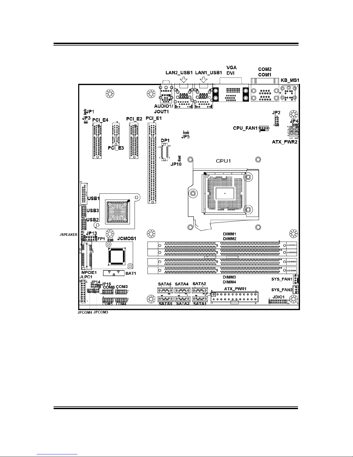
3.3 Component Locations
BU-2509 Connector, Jumper and Component Locations (Top Side)
Note 1: BS-W025 uses motherboard BU-2509
Note 2: C236 SKU has SATA1~6, JDIMM1~4, PCI_E1~4 available. Q170
SKU has SATA1~6, JDIMM1~4, PCI_E1~4 available. H110 SKU only
has SATA1~4, JDIMM2, 4, PCI_E1~3 available. USB1 is not
available for H110 SKU. DP1 is not available for BU-2509RA-D0P /
D1P / D6P.
Page 23
Chapter 3 Hardware Configuration
BS-W025 SERIES USER MANUAL
Page: 3-5
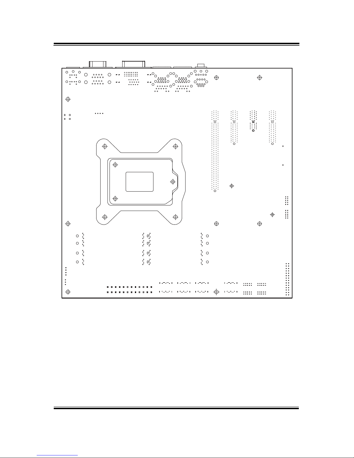
BU-2509 Connector, Jumper and Component Locations (BOT Side)
Page 24
Chapter 3 Hardware Configuration
BS-W025 SERIES USER MANUAL
Page: 3-6
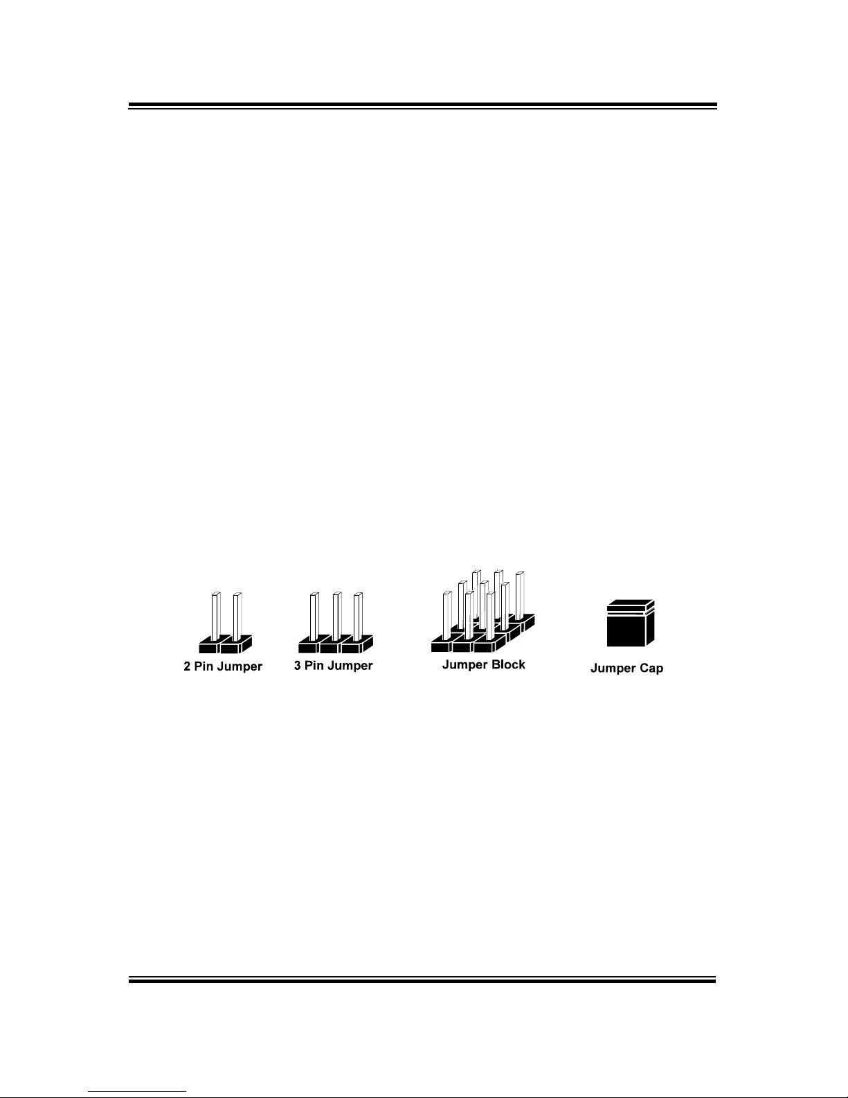
3.4 How To Set Jumpers
You can configure your board by setting jumpers. Jumper is consists of two
or three metal pins with a plastic base mounted on the card, and by using a
small plastic "cap", Also known as the jumper cap (with a metal contact
inside), you are able to connect the pins. So you can set-up your hardware
configuration by "open" or "close" pins.
The jumper can be combined into sets that called jumper blocks. When the
jumpers are all in the block, you have to put them together to set up the
hardware configuration. The figure below shows how this looks like.
Jumpers and Caps
If a jumper has three pins (for examples, labelled PIN1, PIN2, and PIN3),
you can connect PIN1 & PIN2 to create one setting by shorting. You can
either connect PIN2 & PIN3 to create another setting. The same jumper
diagrams are applied all through this manual. The figure below shows what
the manual diagrams look and what they represent.
Page 25

Chapter 3 Hardware Configuration
BS-W025 SERIES USER MANUAL
Page: 3-7
Jumper Diagrams
2 pin Jumper
looks like this
Jumper Cap
looks like this
3 pin Jumper
looks like this
Jumper Block
looks like this
Jumper Settings
Looks like this
3 pin Jumper
2-3 pin close(enabled)
Looks like this
Jumper Block
1-2 pin close(enabled)
2 pin Jumper close(enabled)
1
1
1
2
1 2
1
1
Looks like this
Page 26
Chapter 3 Hardware Configuration
BS-W025 SERIES USER MANUAL
Page: 3-8
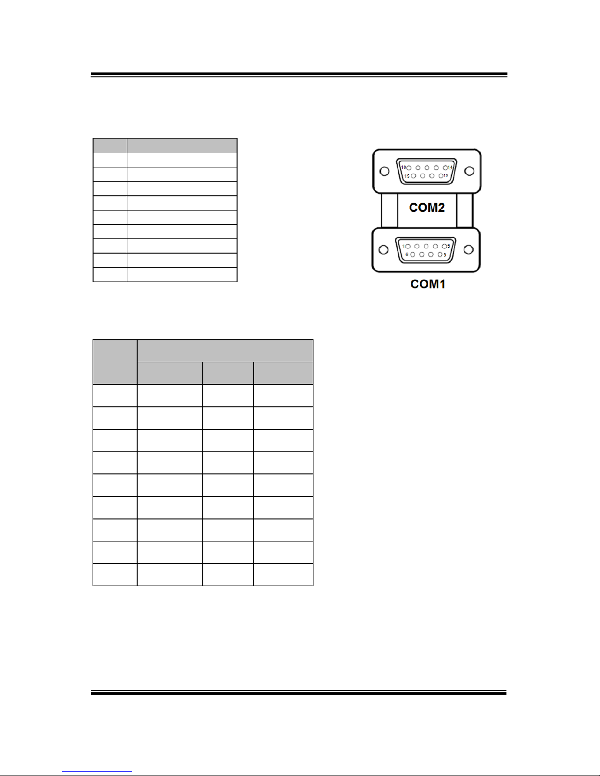
3.5 COM Port and Connectors
COM1: COM1 Connector, fixed as RS-232.
PIN
ASSIGNMENT
1
DCD#
2
RX
3
TX
4
DTR#
5
GND
6
DSR#
7
RTS#
8
CTS#
9
RI#
COM2: COM2 Connector selectable as RS-232/422/485.
The pin assignments are as follows:
PIN
Signal
RS-232
RS-422
RS-485
10
DCD#
TX-
RS-485-
11
RX
TX+
RS-485+
12
TX
RX+
NC
13
DTR#
RX-
NC
14
GND
GND
GND
15
DSR#
NC
NC
16
RTS#
NC
NC
17
CTS#
NC
NC
18
RI#
NC
NC
COM2/
Page 27

Chapter 3 Hardware Configuration
BS-W025 SERIES USER MANUAL
Page: 3-9
COM3/COM4/COM5/COM6 Connector
COM3, COM4, COM5, COM6: COM Connector, fixed as RS-232.
PIN
ASSIGNMENT
PIN
ASSIGNMENT
1
DCD#
6
DSR#
2
RX
7
RTS#
3
TX
8
CTS#
4
DTR#
9
RI#
5
GND
10
Note: Pin 9 is selectable for RI, +5V or +12V for COM3
and COM4 only.
COM3/
COM4/
COM5/
COM6
Page 28
Chapter 3 Hardware Configuration
BS-W025 SERIES USER MANUAL
Page: 3-10
3.6 Clear CMOS Data Selection
JCMOS1: Clear CMOS Data Selection
Selection
Jumper Setting
Jumper Illustration
Normal
1-2
JCMOS1
Clear CMOS
2-3
JCMOS1
Note 1: Manufacturing Default is Normal.
Note 2: To clear CMOS data, users must power off the computer and set the jumper
to “Clear CMOS” as shown above. After 5 to 6 seconds, set the jumper back
to “NC” and power on the computer.
Page 29
Chapter 3 Hardware Configuration
BS-W025 SERIES USER MANUAL
Page: 3-11
3.7 COM Port RI / Voltage Selection
COM3 and COM4 RI & Voltage Selection
Selection
Jumper Setting
Jumper Illustration
RI
1-2
JPCOM3/JPCOM4
12V
3-4
JPCOM3/JPCOM4
5V
5-6
JPCOM3/JPCOM4
Note: Manufacturing default is RI.
Page 30

Chapter 3 Hardware Configuration
BS-W025 SERIES USER MANUAL
Page: 3-12
3.8 Digital I/O Port Connector
JDIO1: Digital Input / Output Port Connector:
PIN
ASSIGNMENT
PIN
ASSIGNMENT
1
VCC5
2
VCC12
3
DIN1
4
DOUT1
5
DIN2
6
DOUT2
7
DIN3
8
DOUT3
9
DIN4
10
DOUT4
11
DIN5
12
DOUT5-
13
DIN6
14
DOUT6
15
DIN7
16
DOUT7
17
DIN8
18
DOUT8
19
GND
20
GND
JDIO1
1
20
2
19
Page 31

Chapter 3 Hardware Configuration
BS-W025 SERIES USER MANUAL
Page: 3-13
3.9 Keyboard & Mouse Port
KB_MS1: PS/2 Keyboard & Mouse Port
Mouse:
PIN
ASSIGNMENT
PIN
ASSIGNMENT
12
NC
11
MSCLK
10
VCC5
9
GND
8
NC
7
MSDATA
Keyboard:
PIN
ASSIGNMENT
PIN
ASSIGNMENT
6
NC
5
KBCLK
4
VCC5
3
GND
2
NC
1
KBDATA
KB_MS1
3
12
4
56
9
78
10
1112
MS
KB
Page 32

Chapter 3 Hardware Configuration
BS-W025 SERIES USER MANUAL
Page: 3-14
3.10 DVI (Digital Video Interface) Port
DVI-D: DVI-D (Digital Video Interface – Digital) function is supported.
The pin assignments are as follows:
PIN
ASSIGNMENT
PIN
ASSIGNMENT
1
TMDS_D2-
13
NC
2
TMDS_D2+
14
VCC5
3
GND
15
GND
4
NC
16
TMDS_HPD
5
NC
17
TMDS_D0-
6
TMDS_CLK
18
TMDS_D0+
7
TMDS_DATA
19
GND
8
NC
20
NC
9
TMDS_D1-
21
NC
10
TMDS_D1+
22
GND
11
GND
23
TMDS_D3+
12
NC
24
TMDS_D3-
A DVI-D connector transfer only digital signals, providing faster transfer rates and
better quality than their predecessor, the VGA cable. It is most commonly used to
connect computer video cards to LCD monitors.
DVI-D
Page 33

Chapter 3 Hardware Configuration
BS-W025 SERIES USER MANUAL
Page: 3-15
3.11 VGA Port
VGA: VGA (Video Graphics Array) Connector
The pin assignments are as follows:
PIN
ASSIGNMENT
1
CRT_RED
2
CRT_GREEN
3
CRT_BLUE
4
NC
5
GND
6
NC
7
GND
8
GND
9
CRT_VCC
10
GND
11
NC
12
CRT_SDA
13
CRT_HSYNC
14
CRT_VSYNC
15
CRT_SCL
VGA
Page 34

Chapter 3 Hardware Configuration
BS-W025 SERIES USER MANUAL
Page: 3-16
3.12 Front Panel Connector
FP1: Front Panel Connector
PIN
ASSIGNMENT
PIN
ASSIGNMENT
1
HDD_LED+
2
PWR_LED+
3
HDD_LED-
4
PWR_LED-
5
GND
6
PWR_BTN
7
RST_BTN
8
GND
9
VCC5 - -
FP1
1
9
2
Page 35

Chapter 3 Hardware Configuration
BS-W025 SERIES USER MANUAL
Page: 3-17
3.13 LAN & USB Port
LAN1_USB1: LAN1 & Two USB 3.0 Ports
LAN1 signals:
PIN
ASSIGNMENT
PIN
ASSIGNMENT
1
MDI_P0
5
MDI_P2
2
MDI_N0
6
MDI_N2
3
MDI_P1
7
MDI_P3
4
MDI_N1
8
MDI_N3
LAN LED Indicator:
Left Side LED
Green Color On7
10/100Mbps LAN Speed Indicator
Orange Color On8
Giga LAN Speed Indicator
Off
No LAN Switch/HUB connected
Right Side LED
Yellow Color Blinking
LAN Message Active
Off
No LAN Message Active
USB 3.0 signals:
PIN
ASSIGNMENT
PIN
ASSIGNMENT
A1
VCC
B1
VCC
A2
USB_N1
B2
USB_N2
A3
USB_P1
B3
USB_P2
A4
GND
B4
GND
A5
USB3_RX_N1
B5
USB3_RX_N2
A6
USB3_RX_P1
B6
USB3_RX_P2
A7
GND
B7
GND
A8
USB3_TX_N1
B8
USB3_TX_N2
A9
USB3_TX_P1
B9
USB3_TX_P2
Green/Orange Yellow
LAN1_USB1
B1 B4
B9 B5
A1 A4
A9 A5
8 1
Page 36

Chapter 3 Hardware Configuration
BS-W025 SERIES USER MANUAL
Page: 3-18
LAN2_USB1: LAN2 & Two USB 3.0 Ports
LAN2 signals:
PIN
ASSIGNMENT
PIN
ASSIGNMENT
1
MDI_P0
5
MDI_P2
2
MDI_N0
6
MDI_N2
3
MDI_P1
7
MDI_P3
4
MDI_N1
8
MDI_N3
LAN LED Indicator:
Left Side LED
Green Color On7
10/100 LAN Speed Indicator
Orange Color On8
Giga LAN Speed Indicator
Off
No LAN Switch/HUB connected
Right Side LED
Yellow Color Blinking
LAN Message Active
Off
No LAN Message Active
USB 3.0 signals:
PIN
ASSIGNMENT
PIN
ASSIGNMENT
A1
VCC
B1
VCC
A2
USB_N3
B2
USB_N4
A3
USB_P3
B3
USB_P4
A4
GND
B4
GND
A5
USB3_RX_N3
B5
USB3_RX_N4
A6
USB3_RX_P3
B6
USB3_RX_P4
A7
GND
B7
GND
A8
USB3_TX_N3
B8
USB3_TX_N4
A9
USB3_TX_P3
B9
USB3_TX_P4
Green/Orange Yellow
LAN2_USB1
B1 B4
B9 B5
A1 A4
A9 A5
8 1
Page 37

Chapter 3 Hardware Configuration
BS-W025 SERIES USER MANUAL
Page: 3-19
3.14 Line-in, Line-out, Mic-in Port
AUDIO1: Line-In, Line-Out & Microphone
The connector can also support only Microphone.
Line-In:
PIN
ASSIGNMENT
32
HD_LINE-IN-L
33
GND
34
GND
35
HD_LINE-IN-R
Line-Out:
PIN
ASSIGNMENT
22
LINE-OUT-L
23
GND
24
GND
25
LINE-OUT-R
MIC-In:
PIN
ASSIGNMENT
1
GND
2
HD_MIC1-L_L
3
GND
4
GND
5
HD_MIC1-R_L
AUDIO1
1 2345
22232425
32333435
424344
Page 38

Chapter 3 Hardware Configuration
BS-W025 SERIES USER MANUAL
Page: 3-20
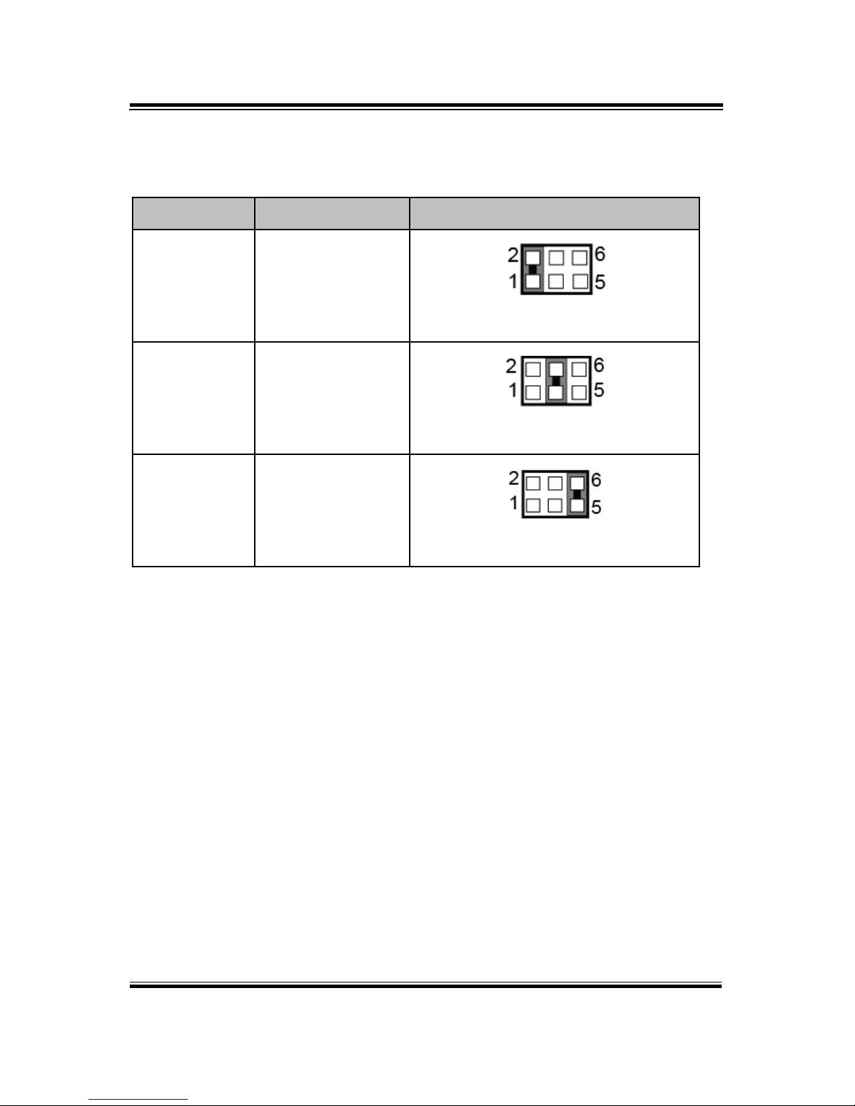
3.15 RS-232/422/485 (COM2) Selection
JP2: RS-232/422/485 (COM2) Selection
The selections are as follows:
***Manufacturing Default – RS-232.
Selection
Jumper Setting
(Pin Closed)
Jumper Illustration
RS-232
Open
JP2
RS-422
1-2, 3-4, 9-10
JP2
RS-485
1-2, 5-6, 7-8
JP2
Page 39

Chapter 3 Hardware Configuration
BS-W025 SERIES USER MANUAL
Page: 3-21
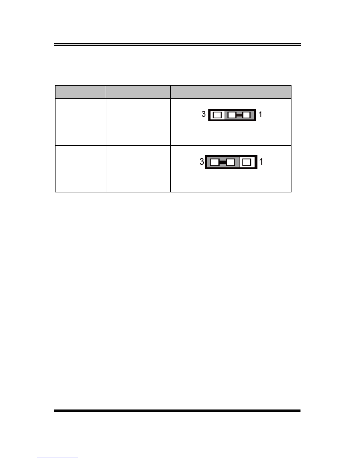
3.16 COM2 Auto Detection Selection
JP4: COM2 Auto Detection Selection
The selections are as follows:
***Manufacturing Default – Auto.
Selection
Jumper Setting
(Pin Closed)
Jumper Illustration
Normal
1-2
JP4
Auto
2-3
JP4
Page 40

Chapter 3 Hardware Configuration
BS-W025 SERIES USER MANUAL
Page: 3-22
3.17 Hardware Power Failure Selection
JP1: Hardware Power Failure Selection
Selection
Jumper Setting
Jumper Illustration
Enable
1-2
JP1
Disable
2-3
JP1
Note: Manufacturing default is Disable.
Page 41

Chapter 3 Hardware Configuration
BS-W025 SERIES USER MANUAL
Page: 3-23
3.18 Flash Descriptor Override Selection
JP3: Flash Descriptor Override Selection
Description: Jumper for enable or disable the permission to updating BIOS ME
firmware.
The selections are as follows:
***Manufacturing Default – Disable.
Selection
Jumper Setting
(Pin Closed)
Jumper Illustration
Disable
Open
JP3
Enable
1-2
JP3
Page 42

Chapter 3 Hardware Configuration
BS-W025 SERIES USER MANUAL
Page: 3-24
3.19 LAN2 Enable / Disable Selection
JP5: LAN2 Enable / Disable Selection
The selections are as follows:
***Manufacturing Default – Enable.
Selection
Jumper Setting
(Pin Closed)
Jumper Illustration
Enable
1-2
JP5
Disable
2-3
JP5
Page 43

Chapter 3 Hardware Configuration
BS-W025 SERIES USER MANUAL
Page: 3-25
3.20 Mini PCIE Voltage Selection
JP13: Mini PCIE Voltage Selection
The selections are as follows:
***Manufacturing Default –3.3V_AUX.
Selection
Jumper Setting
(Pin Closed)
Jumper Illustration
3.3V
1-2
JP13
3.3V_AUX
2-3
JP13
Page 44

Chapter 3 Hardware Configuration
BS-W025 SERIES USER MANUAL
Page: 3-26
3.21 VCCIO Voltage Selection
JP10: VCCIO Voltage Selection
The selections are as follows:
***Manufacturing Default – 0.95V.
Selection
Jumper Setting
(Pin Closed)
Jumper Illustration
1.0V
1-2
JP10
0.95V
2-3
JP10
Page 45

Chapter 3 Hardware Configuration
BS-W025 SERIES USER MANUAL
Page: 3-27
3.22 MINI PCI Express Slot
MPCIE1: Mini-PCI Express Slot
PIN
ASSIGNMENT
PIN
ASSIGNMENT
1
WAKE_N
2
3.3V_SB
3
NC
4
GND
5
NC
6
1.5V
7
CLKREQ#
8
NC
9
GND
10
NC
11
REFCLK-
12
NC
13
REFCLK+
14
NC
15
GND
16
NC
17
NC
18
GND
19
NC
20
NC
21
GND
22
PERST#
23
PE_RX_N
24
3.3V_SB
25
PE_RX_P
26
GND
27
GND
28
1.5V
29
GND
30
SMB_CLK
31
PE_TX_N
32
SMB_DATA
33
PE_TX_P
34
GND
35
GND
36
USB_N
37
GND
38
USB_P
39
3.3V_SB
40
GND
41
3.3V_SB
42
NC
43
GND
44
NC
45
NC
46
NC
47
NC
48
1.5V
49
NC
50
GND
51
NC
52
3.3V_SB
MPCIE1
Page 46

Chapter 3 Hardware Configuration
BS-W025 SERIES USER MANUAL
Page: 3-28
3.23 PCI Express Slots
PCI_E1 (X16): PCI_E1 (PCIE X16)
PIN
ASSIGNMENT
PIN
ASSIGNMENT
PIN
ASSIGNMENT
A1
PRSNT#1
A21
HSIP1
A41
GND
A2
+ 12V
A22
HSIN1
A42
GND
A3
+ 12V
A23
GND
A43
HSIP6
A4
GND
A24
GND
A44
HSIN6
A5
NC
A25
HSIP2
A45
GND
A6
NC
A26
HSIN2
A46
GND
A7
NC
A27
GND
A47
HSIP7
A8
NC
A28
GND
A48
HSIN7
A9
+ 3.3V
A29
HSIP3
A49
GND
A10
+ 3.3V
A30
HSIN3
A50
RSVD
A11
PERST#
A31
GND
A51
GND
A12
GND
A32
RSVD
A52
HSIP8
A13
REFCLK+
A33
RSVD
A53
HSIN8
A14
REFCLK-
A34
GND
A54
GND
A15
GND
A35
HSIP4
A55
GND
A16
HSIP0
A36
HSIN4
A56
HSIP9
A17
HSIN0
A37
GND
A57
HSIN9
A18
GND
A38
GND
A58
GND
A19
RSVD
A39
HSIP5
A59
GND
A20
GND
A40
HSIN5
A60
HSIP10
A61
HSIN10
A69
HSIN12
A77
HSIN14
A62
GND
A70
GND
A78
GND
A63
GND
A71
GND
A79
GND
A64
HSIP11
A72
HSIP13
A80
HSIP15
PCI_E1
A1
A11
A12
A82
B1
B11
B12
B82
Page 47

Chapter 3 Hardware Configuration
BS-W025 SERIES USER MANUAL
Page: 3-29
PIN
ASSIGNMENT
PIN
ASSIGNMENT
PIN
ASSIGNMENT
A65
HSIN11
A73
HSIN13
A81
HSIN15
A66
GND
A74
GND
A82
GND
A67
GND
A75
GND - -
A68
HSIP12
A76
HSIP14 - -
PIN
ASSIGNMENT
PIN
ASSIGNMENT
PIN
ASSIGNMENT
B1
+ 12V
B22
GND
B43
GND
B2
+ 12V
B23
HSOP2
B44
GND
B3
+ 12V
B24
HSON2
B45
HSOP7
B4
GND
B25
GND
B46
HSON7
B5
SMB_CLK
B26
GND
B47
GND
B6
SMB_DATA
B27
HSOP3
B48
PRSNT#2
B7
GND
B28
HSON3
B49
GND
B8
+ 3.3V
B29
GND
B50
HSOP8
B9
NC
B30
RSVD
B51
HSON8
B10
+ 3.3V_AXU
B31
PRSNT#2
B52
GND
B11
WAKE#
B32
GND
B53
GND
B12
RSVD
B33
HSOP4
B54
HSOP9
B13
GND
B34
HSON4
B55
HSON9
B14
HSOP0
B35
GND
B56
GND
B15
HSON0
B36
GND
B57
GND
B16
GND
B37
HSOP5
B58
HSOP10
B17
PRSNT#2
B38
HSON5
B59
HSON10
B18
GND
B39
GND
B60
GND
B19
HSOP1
B40
GND
B61
GND
B20
HSON1
B41
HSOP6
B62
HSOP11
B21
GND
B42
HSON6
B63
HSON11
B64
GND
B71
HSON13
B78
HSIP15
B65
GND
B72
GND
B79
HSIN15
B66
HSOP12
B73
GND
B80
GND
B67
HSON12
B74
HSOP14
B81
PRSNT#2
B68
GND
B75
HSIN14
B82
RSVD
B69
GND
B76
GND - -
B70
HSOP13
B77
GND - -
Page 48

Chapter 3 Hardware Configuration
BS-W025 SERIES USER MANUAL
Page: 3-30
PCI_E2, PCI_E4 (X4): PCI_E2, PCI_E4 (PCIE X4)
PCI_E2, PCI_E4 are only supported in C236 and Q170 SKU.
Note1: H110 SKU PCI_E2 only supports PCIE X 1.
PIN
ASSIGNMENT
PIN
ASSIGNMENT
PIN
ASSIGNMENT
A1
PRSNT#1
A12
GND
A23
GND
A2
+ 12V
A13
REFCLK+
A24
GND
A3
+ 12V
A14
REFCLK-
A25
HSIP2
A4
GND
A15
GND
A26
HSIN2
A5
NC
A16
HSIP0
A27
GND
A6
NC
A17
HSIN0
A28
GND
A7
NC
A18
GND
A29
HSIP3
A8
NC
A19
RSVD
A30
HSIN3
A9
+ 3.3V
A20
GND
A31
GND
A10
+ 3.3V
A21
HSIP1
A32
RSVD
A11
PERST#
A22
HSIN1 - -
B1
+ 12V
B12
RSVD
B23
HSOP2
B2
+ 12V
B13
GND
B24
HSON2
B3
+ 12V
B14
HSOP0
B25
GND
B4
GND
B15
HSON0
B26
GND
B5
SMB_CLK
B16
GND
B27
HSOP3
B6
SMB_DATA
B17
PRSNT#2
B28
HSON3
B7
GND
B18
GND
B29
GND
B8
+ 3.3V
B19
HSOP1
B30
RSVD
B9
NC
B20
HSON1
B31
PRSNT#2
B10
+ 3.3V_AXU
B21
GND
B32
GND
B11
WAKE#
B22
GND - -
PCI_E2/PCI_E4
A1
A11
A12
B1
B11
B12
B32
A32
Page 49

Chapter 3 Hardware Configuration
BS-W025 SERIES USER MANUAL
Page: 3-31
PCI_E3 (X1): PCI_E3 (PCIE X1)
PIN
ASSIGNMENT
PIN
ASSIGNMENT
A1
PRSNT#1
A10
+ 3.3V
A2
+ 12V
A11
PERST#
A3
+ 12V
A12
GND
A4
GND
A13
REFCLK+
A5
NC
A14
REFCLK-
A6
NC
A15
GND
A7
NC
A16
HSIP0
A8
NC
A17
HSIN0
A9
+ 3.3V
A18
GND
PIN
ASSIGNMENT
PIN
ASSIGNMENT
B1
+ 12V
B10
+ 3.3V_AXU
B2
+ 12V
B11
WAKE#
B3
+ 12V
B12
RSVD
B4
GND
B13
GND
B5
SMB_CLK
B14
HSOP0
B6
SMB_DATA
B15
HSON0
B7
GND
B16
GND
B8
+ 3.3V
B17
PRSNT#2
B9
NC
B18
GND
PCI_E3
Page 50

Chapter 3 Hardware Configuration
BS-W025 SERIES USER MANUAL
Page: 3-32
3.24 CPU / System Fan Connectors
CPU_FAN1: CPU Fan Connector
SYS_FAN1: System Fan Connector 1
PIN
ASSIGNMENT
1
GND
2
VCC12
3
CPU_FANTAC
4
CPU_FANCTRL
SYS_FAN2: System Fan Connector 2
PIN
ASSIGNMENT
3
NC
2
VCC12
1
GND
CPU_FAN1
SYS_FAN1
4
1
SYS_FAN2
1
3
Page 51

Chapter 3 Hardware Configuration
BS-W025 SERIES USER MANUAL
Page: 3-33
3.25 Serial ATA (SATA) Connectors
SATA1, SATA2, SATA3, SATA4, SATA5,
SATA6: SATA Connectors
SATA1-6 Pin Assignment:
PIN
ASSIGNMENT
1
GND
2
SATA_TX_P
3
SATA_TX_N
4
GND
5
SATA_RX_N
6
SATA_RX_P
7
GND
Notes:
1. C236 SKU supports SATA1~SATA6.
2. Q170 SKU supports SATA1~SATA6.
3. H110 SKU supports SATA1~SATA4.
SATA1/
SATA3/
SATA5/
SATA2/
SATA4/
SATA6/
Page 52

Chapter 3 Hardware Configuration
BS-W025 SERIES USER MANUAL
Page: 3-34
3.26 Internal USB 3.0 Connector
USB1: Internal USB 3.0 Connector
PIN
ASSIGNMENT
PIN
ASSIGNMENT
- - 1
VCC5
19
VCC5
2
USB3_RX_N
18
USB3_RX_N
3
USB3_RX_P
17
USB3_RX_P
4
GND
16
GND
5
USB3_TX_N
15
USB3_TX_N
6
USB3_TX_P
14
USB3_TX_P
7
GND
13
GND
8
USB2_N
12
USB2_N
9
USB2_P
11
USB2_P
10
GND
Note: USB1 is only available for C236/Q170 SKU, not available for
H110 SKU.
3.27 Internal USB 2.0 Conncetors
USB2, USB3: Internal USB 2.0 Connector
PIN
ASSIGNMENT
PIN
ASSIGNMENT
10
GND
9
NC
8
GND
7
GND
6
USB2_P
5
USB2_P
4
USB2_N
3
USB2_N
2
VCC5
1
VCC5
USB1
1
1011
19
USB2/
USB3
10
9
1
2
Page 53

Chapter 3 Hardware Configuration
BS-W025 SERIES USER MANUAL
Page: 3-35
3.28 Display Port Connector
DP1: Display Port Connector
PIN
ASSIGNMENT
PIN
ASSIGNMENT
19
VCC5
20
VCC3
17
AUX
18
VCC3
15
AUX+
16
HPD
13
AUX_EN#
14
GND
11
GND
12
DATA3-
9
DATA2-
10
DATA3+
7
DATA2+
8
GND
5
GND
6
DATA1-
3
DATA0-
4
DATA1+
1
DATA0+
2
GND
NOTE: BU-2509RA-D0P / D1P / D6P don’t support DP.
DP1
Page 54

Chapter 3 Hardware Configuration
BS-W025 SERIES USER MANUAL
Page: 3-36
3.29 Power Input Connectors
ATX_PWR1: ATX Connector
The pin assignments are as follows:
PIN
ASSIGNMENT
PIN
ASSIGNMENT
13
+ 3.3V
1
+ 3.3V
14
-12V
2
+ 3.3V
15
GND
3
GND
16
PSON
4
+ 5V
17
GND
5
GND
18
GND
6
+ 5V
19
GND
7
GND
20
-5V
8
POK
21
+ 5V
9
+ 5V_SB
22
+ 5V
10
+ 12V
23
+ 5V
11
+ 12V
24
GND
12
+ 3.3V
ATX_PWR2: Power Connector
PIN
ASSIGNMENT
PIN
ASSIGNMENT
4
+12V
1
GND
3
+12V
2
GND
ATX_PWR1
ATX_PWR2
Page 55

Chapter 3 Hardware Configuration
BS-W025 SERIES USER MANUAL
Page: 3-37
3.30 Speaker Connector
JSPEAKER: Speaker Connector
PIN
ASSIGNMENT
4
SPKR_SIGNAL
3
SPKR_SIGNAL
2
SPKR_SIGNAL
1
SPKR_VCC
3.31 LPC Connector
JLPC1: LPC Connector
PIN
ASSIGNMENT
PIN
ASSIGNMENT
20
DREQ0
19
SUS_TAT
18
CLK RUN
17
GND
16
SERIRQ
15
3VSB
14
SMBDATA
13
SMBCLK
12
GND
11
LAD0
10
LAD1
9
VCC3
8
LAD2
7
LAD3
6
VCC5
5
RESET
4
NC 3 FRAME
2
GND
1
CLK
JSPEAKER
1
4
JLPC1
1
20
2
19
Page 56

BS-W025 SERIES USER MANUAL
Page: 4-1
4 Software Utilities
This chapter comprises the detailed information of drivers of
BS-W025.
The following sections are included:
• Introduction.
• Installing Intel RST Driver Utility
• Intel® RapidStorage Technology Option ROM
Page 57

Chapter 4 Software Utilities
BS-W025 SERIES USER MANUAL
Page: 4-2
4.1 Introduction
Enclosed with the BS-W025 Series package is our driver utilities
contained in a DVD-ROM disk. Refer to the following table for driver
locations:
Layer 1
\API Package
Folder
\DRIVER
Folder
\USER MANUAL
Folder
README
PDF file
Layer 2 \API Package folder
\DEMO PROJECT
folder
Demo AP
\Prox API Standard
folder
\Document folder
Guide
Page 58

Chapter 4 Software Utilities
BS-W025 SERIES USER MANUAL
Page: 4-3
Layer 2 \DRIVER folder
\Flash BIOS
folder
BIOS & Updating tool
\Platform
folder
Driver
1. The sequence of setup is as follows:
(1) Main Chip
(2) KMDF(Win7 only)
(3) Intel(R) ME Package
(4) Graphics
(5) RST
(5) LAN
(6) SOUND
(7) USB3.0 (Win7 only)
2. You will be prompted to reboot when installation is
completed.
Main Chip /Intel® Skylake CPU
Main board version: RA
for Windows 7
32bit
10.1.1
64bit
10.1.1
for Windows
Embedded 8.1
32bit
NA
64bit
10.1.1
for Windows 10
32bit
NA
64bit
10.1.1
Page 59

Chapter 4 Software Utilities
BS-W025 SERIES USER MANUAL
Page: 4-4
\Platform
folder
Windows update KMDF & MBI
Main board version: RA
for Windows 7
32bit
kmdf-1.11-Win-6.
1-x86
64bit
kmdf-1.11-Win-6.
1-x64
for Windows Embedded
8.1
32bit
NA
64bit
NA
for Windows 10
32bit
NA
64bit
NA
Intel® ME Package
Main board version: RA
for Windows 7
32bit
11.0.0.1174
64bit
11.0.0.1174
for Windows Embedded
8.1
32bit
NA
64bit
11.0.0.1174
for Windows 10
32bit
NA
64bit
11.0.0.1174
Graphics /Intel® HD Graphics 530
Main board version: RA
for Windows 7
Sky Lake
32bit
20.19.15.4463
64bit
15.45.14.64.4590
for Windows Embedded
8.1
Sky Lake
32bit
NA
64bit
15.45.14.64.4590
for Windows 10
Kaby Lake & Sky Lake
32bit
NA
64bit
15.45.14.64.4590
Page 60

Chapter 4 Software Utilities
BS-W025 SERIES USER MANUAL
Page: 4-5
RST/
Main board version: RA
for Windows 7
32bit
14.8.0.1042
64bit
14.8.0.1042
for Windows Embedded
8.1
32bit
NA
64bit
14.8.0.1042
for Windows 10
32bit
NA
64bit
14.8.0.1042
LAN Chip/ INTEL i219
Main board version: RA
for Windows 7
32bit
12.15.23.1
64bit
12.15.23.1
for Windows Embedded
8.1
32bit
NA
64bit
12.15.23.1
for Windows 10
32bit
NA
64bit
12.15.23.1
INTEL i210
Main board version: RA
for Windows 7
32bit
12.13.27.0
64bit
12.13.27.0
for Windows Embedded
8.1
32bit
NA
64bit
12.14.7.0
for Windows 10
32bit
NA
64bit
12.14.7.0
Page 61

Chapter 4 Software Utilities
BS-W025 SERIES USER MANUAL
Page: 4-6
Sound Codec / Realtek ALC888S
Main board version: RA
for Windows 7
32bit
6.0.1.7541
64bit
6.0.1.7541
for Windows Embedded
8.1
32bit
NA
64bit
6.0.1.7541
for Windows 10
32bit
NA
64bit
6.0.1.7541
USB 3.0
for Windows7
32bit
4.0.4.51
64bit
4.0.4.51
Note1: Install the driver utilities immediately after the OS installation is completed.
Note2: BS-W025RA-01B uses motherboard BU-2509R*-00N which uses PCH
Q170.
Page 62

Chapter 4 Software Utilities
BS-W025 SERIES USER MANUAL
Page: 4-7
4.2 Installing Intel RST Driver Utility (For Q170/C236 SKU)
The Intel® Rapid Storage Technology (Intel® RST) driver supports
RAID 0, 1 in Q170/C236 SKU for 2 x 2.5” SATAIII HDD/SSD. To
install the RAID/RST driver utility, follow the steps below:
1. Insert the driver disk into a DVD-ROM device.
2. Enter the RST folder where the driver is located.
3. Select Windows 7 (32/64-bit) / Windows 8.1 (64-bit) / Windows 10
(64-bit) for your OS platform.
4. Click SetupRST.exe driver installation file for driver installation.
5. Follow the on-screen instructions to complete the installation.
6. Once the installation is completed, shut down the system and
restart BS-W025 for the changes to take effect.
Note: The RAID driver utility is not supported for H110 SKU.
4.3 Intel® RapidStorage Technology Option ROM
The Intel
®
Rapid Storage Technology option ROM provides the
following:
Pre-operating system user interface for RAID volume management
Ability to create, delete and reset RAID volumes
RAID recovery
Accessing Intel
®
Rapid Storage Technology Option ROM User
Interface
To enter the Intel
®
Rapid Storage Technology option ROM user
interface, press Ctrl-I when prompted during the Power-On Self-Test
(POST).
Page 63

Chapter 4 Software Utilities
BS-W025 SERIES USER MANUAL
Page: 4-8
Option ROM prompt:
In the user interface, the hard drive(s) and hard drive information listed
for your system will differ from the example in the figure below:
Option ROM user interface:
Page 64

BS-W025 SERIES USER MANUAL
Page: 5-1
5 BIOS SETUP
This chapter guides users how to configure the basic
system configurations via the BIOS Setup Utilities. The
information of the system configuration is saved in
battery-backed CMOS RAM and BIOS NVRAM so that
the Setup information is retained when the system is
powered off. The BIOS Setup Utilities consist of the
following menu items:
• Main Menu
• Advanced Menu
• Chipset Menu
• Boot Menu
• Security Menu
• Save & Exit Menu
Page 65

Chapter 5 BIOS Setup
BS-W025 SERIES USER MANUAL
Page: 5-2
5.1 Introduction
The BS-W025 System uses an AMI (American Megatrends Incorporated) Aptio BIOS
that is stored in the Serial Peripheral Interface Flash Memory (SPI Flash) and can be
updated. The SPI Flash contains the built-in BIOS setup program, Power-On Self-Test
(POST), PCI auto-configuration utility, LAN EEPROM information, and Plug and
Play support.
Aptio is AMI’s BIOS firmware based on the UEFI (Unified Extensible Firmware
Interface) specifications and the Intel Platform Innovation Framework for EFI. The
UEFI specification defines an interface between the operating system and platform
firmware. The interface consists of data tables that contain platform-related
information, boot service calls, and runtime service calls that are available to the
operating system and its loader. These elements have combined to provide a standard
environment for booting the operating system and running pre-boot applications.
The diagram below shows the Extensible Firmware Interface’s location in the
software stack.
Figure 5-1. Extensible Firmware Interface Diagram
EFI BIOS provides an user interface that allows you to modify hardware
configuration, e.g. change the system date and time, enable/disable a system
component, determine bootable device priority, set up personal password, etc., which
is convenient for engineers to perform modifications and customize the computer
Page 66

Chapter 5 BIOS Setup
BS-W025 SERIES USER MANUAL
Page: 5-3
system and allows technicians to troubleshoot the occurred errors when the hardware
is faulty.
The BIOS setup menu allows users to view and modify the BIOS settings for the
computer. After the system is powered on, users can access the BIOS setup menu by
pressing <Del> or <Esc> immediately while the POST message is running before the
operating system is loading.
Users will need to set up the system configuration from the BIOS Setup Utility when
any of the following conditions occurs:
1. You are starting your system for the first time.
2. You have changed the hardware in your system or the hardware becomes faulty.
3. The system configuration is reset after the user configures to clear CMOS data via
the JP3 jumper.
4. The power of the CMOS RAM became lost and the system configuration has been
erased.
All the menu settings are described in details in this chapter.
5.2 Accessing Setup Utility
After the system is powered on, BIOS will enter the Power-On Self-Test (POST)
routines and the POST message will be displayed:
Figure 5-2. POST Screen with AMI Logo
Press <Del> or <Esc> to access the Setup Utility program and the Main menu of
the Aptio Setup Utility will appear on the screen as below:
Page 67

Chapter 5 BIOS Setup
BS-W025 SERIES USER MANUAL
Page: 5-4
BIOS Setup Menu Initialization Screen
You may move the cursor by <↑> and <↓> keys to highlight the individual menu
items. As you highlight each item, a brief description of the highlighted selection will
appear on the right side of the screen.
The language of the BIOS setup menu interface and help messages are shown in US
English. You may use <↑> or <↓> key to select among the items and press <Enter> to
confirm and enter the sub-menu. The following table provides the list of the
navigation keys that you can use while operating the BIOS setup menu.
Page 68

Chapter 5 BIOS Setup
BS-W025 SERIES USER MANUAL
Page: 5-5
BIOS Setup
Navigation Key
Description
<←> and <→>
Select a different menu screen (move the cursor from the
selected menu to the left or right).
<↑> and <↓>
Select a different item (move the cursor from the
selected item upwards or downwards)
<Enter>
Execute the command or select the sub-menu.
<F2>
Load the previous configuration values.
<F3>
Load the default configuration values.
<F4>
Save the current values and exit the BIOS setup menu.
<Esc>
Close the sub-menu.
Trigger the confirmation to exit BIOS setup menu.
BIOS Messages
This section describes the alert messages generated by the board’s BIOS. These
messages would be shown on the monitor when certain recoverable errors/events
occur during the POST stage. The table bellow gives an explanation of the BIOS alert
messages:
BIOS Message
Explanation
A first boot or NVRAM
reset condition has been
detected.
BIOS has been updated or the battery was replaced.
The CMOS defaults
were loaded.
Default values have been loaded after the BIOS was
updated or the battery was replaced.
The CMOS battery is
bad or has been recently
replaced.
The battery may be losing power and users should
replace the battery immediately. Also, this message is
displayed once the new battery is replaced.
Page 69

Chapter 5 BIOS Setup
BS-W025 SERIES USER MANUAL
Page: 5-6
5.3 Main
Menu Path Main
The Main menu allows you to view the BIOS Information and change the system
date and time. Use tab to switch between date elements. Use <↑> or <↓> arrow keys
to highlight the item and enter the value you want in each item. This screen also
displays the BIOS version (project) and BIOS Build Date and Time.
Main Screen
BIOS Setting
Options
Description/Purpose
BIOS Vendor
No changeable options
Displays the name of the BIOS vendor.
Core Version
No changeable options
Displays the current BIOS core version.
Compliancy
No changeable options
Displays the current UEFI version.
Project Version
No changeable options
Displays the version of the BIOS currently
installed on the platform.
Build Date and
Time
No changeable options
Displays the date that the current BIOS
version is built.
System Date
Month, day, year
Sets the system date. The format is [Day
Month/ Date/ Year]. Users can directly
enter values or use <+> or <-> arrow keys
to increase/decrease it. The “Day” is
automatically changed.
System Time
Hour, minute, second
Sets the system time. The format is [Hour:
Page 70

Chapter 5 BIOS Setup
BS-W025 SERIES USER MANUAL
Page: 5-7
BIOS Setting
Options
Description/Purpose
Minute: Second]. Users can directly enter
values or use <+> or <-> arrow keys to
increase/decrease it.
5.4 Advanced
Menu Path Advanced
This menu provides advanced configurations such as Trusted Computing, ACPI
Settings, PCH-FW Configuration, F81866 Super IO Configuration, Hardware Monitor,
F81866 Watchdog, CPU Configuration, SATA Configuration, Network Stack
Configuration and USB Configuration.
Advanced Menu Screen
BIOS Setting
Options
Description/Purpose
Trusted Computing
Sub-Menu
Trusted Computing Settings.
ACPI Settings
Sub-Menu
System ACPI Parameters.
PCH-FW
Configuration
Sub-Menu
Management Engine Technology
Parameters.
F81866 Super IO
Configuration
Sub-Menu
System Super IO Chip Parameters.
Page 71

Chapter 5 BIOS Setup
BS-W025 SERIES USER MANUAL
Page: 5-8
BIOS Setting
Options
Description/Purpose
Hardware Monitor
Sub-Menu
Monitor hardware status.
F81866 Watchdog
Sub-Menu
F81866 Watchdog Parameters.
CPU Configuration
Sub-Menu
CPU Configuration Parameters.
SATA Configuration
Sub-Menu
SATA Device Options Settings.
Network Stack
Configuration
Sub-Menu
Network Stack Settings.
USB Configuration
Sub-Menu
USB Configuration Parameters.
Advanced - Trusted Computing
Menu Path Advanced > Trusted Computing
The Trusted Computing allows users to enable/disable BIOS support for security
device. The operating system will not show Security Device. The TCG EFI protocol
and INT1A interface will not be available.
Trusted Computing Screen
BIOS Setting
Options
Description/Purpose
Security Device
Support
- Disabled
- Enabled
Enables or Disables BIOS support for
security device. O.S will not show security
Device. TCG EFI protocol and INT1A
interface will not be available.
Page 72

Chapter 5 BIOS Setup
BS-W025 SERIES USER MANUAL
Page: 5-9
BIOS Setting
Options
Description/Purpose
Security Device
Status
No changeable
options
Security Device Information.
Page 73

Chapter 5 BIOS Setup
BS-W025 SERIES USER MANUAL
Page: 5-10
Advanced - ACPI Settings
Menu Path Advanced > ACPI Settings
The ACPI Settings allows users to configure relevant ACPI (Advanced Configuration
and Power Management Interface) settings, such as enable/disable Hibernation, ACPI
Sleep State, lock legacy resources, etc.
ACPI Settings Screen
BIOS Setting
Options
Description/Purpose
Enable Hibernation
(S4)
- Disabled
- Enabled (default)
Enables or Disables System ability to
Hibernate (OS/S4 Sleep State). This option
may be not effective with some OS.
ACPI Sleep State
- Suspend Disabled
- S3 (Suspend to
RAM)
Selects the highest ACPI sleep state the
system will enter when the SUSPEND button
is pressed.
Lock Legacy
Resources
- Disabled
- Enabled
Enables or Disables Lock of Legacy
Resources.
S3 Video Repost
- Disabled
- Enabled
Enables or Disables S3 Video Repost.
Page 74

Chapter 5 BIOS Setup
BS-W025 SERIES USER MANUAL
Page: 5-11
Advanced – PCH-FW Configuration
Menu Path Advanced > PCH-FW Configuration
The PCH-FW allows users to view the information about ME (Management Engine)
firmware information, such ME firmware version, firmware mode, firmware type and
firmware SKU.
PCH-FW Configuration Screen
BIOS Setting
Options
Description/Purpose
ME Firmware
Version
No changeable options
Displays the ME Firmware Version.
ME Firmware
Mode
No changeable options
Displays the ME Firmware Mode.
ME Firmware
SKU
No changeable options
Displays the ME Firmware SKU.
Page 75

Chapter 5 BIOS Setup
BS-W025 SERIES USER MANUAL
Page: 5-12
Advanced – F81866 Super IO Configuration
Menu Path Advanced > F81866 Super IO Configuration
F81866 Super IO Configuration Screen
BIOS Setting
Options
Description/Purpose
Serial Port 1
Configuration
Sub-menu
Sets parameters of Serial Port 1
(COMA).
Serial Port 2
Configuration
Sub-menu
Sets parameters of Serial Port 2
(COMB).
Serial Port 3
Configuration
Sub-menu
Sets parameters of Serial Port 3
(COMC).
Serial Port 4
Configuration
Sub-menu
Sets parameters of Serial Port 4
(COMD).
Serial Port 5
Configuration
Sub-menu
Sets parameters of Serial Port 5
(COME).
Serial Port 6
Configuration
Sub-menu
Sets parameters of Serial Port 6
(COMF).
Page 76

Chapter 5 BIOS Setup
BS-W025 SERIES USER MANUAL
Page: 5-13
Menu Path Advanced > F81866 Super IO Configuration > Serial Port 1
Configuration
Serial Port 1 Configuration Screen
BIOS Setting
Options
Description/Purpose
Serial Port
- Disabled
- Enabled
Enables or Disables Serial
Port 1.
Device Settings
No changeable options
Displays the current settings
of Serial Port 1.
Change Settings
- Auto
- IO=3F8h; IRQ=4;
- IO=3F8h; IRQ=3,4,5,6,7,9,10,11,12;
- IO=2F8h; IRQ=3,4,5,6,7,9,10,11,12;
- IO=3E8h; IRQ=3,4,5,6,7,9,10,11,12;
- IO=2E8h; IRQ=3,4,5,6,7,9,10,11,12;
Selects IRQ and I/O
resource settings for Serial
Port 1.
Page 77

Chapter 5 BIOS Setup
BS-W025 SERIES USER MANUAL
Page: 5-14
Menu Path Advanced > F81866 Super IO Configuration > Serial Port 2
Configuration
Serial Port 2 Configuration Screen
BIOS Setting
Options
Description/Purpose
Serial Port
- Disabled
- Enabled
Enables or Disables Serial
Port 2.
Device Settings
No changeable options
Displays the current settings
of Serial Port 2.
Change Settings
- Auto
- IO=2F8h; IRQ=3;
- IO=3F8h; IRQ=3,4,5,6,7,9,10,11,12;
- IO=2F8h; IRQ=3,4,5,6,7,9,10,11,12;
- IO=3E8h; IRQ=3,4,5,6,7,9,10,11,12;
- IO=2E8h; IRQ=3,4,5,6,7,9,10,11,12;
Selects IRQ and I/O
resource settings for Serial
Port 2.
Page 78

Chapter 5 BIOS Setup
BS-W025 SERIES USER MANUAL
Page: 5-15
Menu Path Advanced > F81866 Super IO Configuration > Serial Port 3
Configuration
Serial Port 3 Configuration Screen
BIOS Setting
Options
Description/Purpose
Serial Port
- Disabled
- Enabled
Enables or Disables Serial
Port 3.
Device Settings
No changeable options
Displays the current settings
of Serial Port 3.
Change Settings
- Auto
- IO=3E8h; IRQ=10;
- IO=3E8h; IRQ=3,4,5,6,7,9,10,11,12;
- IO=2E8h; IRQ=3,4,5,6,7,9,10,11,12;
- IO=2F0h; IRQ=3,4,5,6,7,9,10,11,12;
- IO=2E0h; IRQ=3,4,5,6,7,9,10,11,12;
Selects IRQ and I/O
resource settings for Serial
Port 3.
Page 79

Chapter 5 BIOS Setup
BS-W025 SERIES USER MANUAL
Page: 5-16
Menu Path Advanced > F81866 Super IO Configuration > Serial Port 4
Configuration
Serial Port 4 Configuration Screen
BIOS Setting
Options
Description/Purpose
Serial Port
- Disabled
- Enabled
Enables or Disables Serial
Port 4.
Device Settings
No changeable options
Displays the current settings
of Serial Port 4.
Change Settings
- Auto
- IO=2E8h; IRQ=5;
- IO=3E8h; IRQ=3,4,5,6,7,9,10,11,12;
- IO=2E8h; IRQ=3,4,5,6,7,9,10,11,12;
- IO=2F0h; IRQ=3,4,5,6,7,9,10,11,12;
- IO=2E0h; IRQ=3,4,5,6,7,9,10,11,12;
Selects IRQ and I/O
resource settings for Serial
Port 4.
Page 80

Chapter 5 BIOS Setup
BS-W025 SERIES USER MANUAL
Page: 5-17
Menu Path Advanced > F81866 Super IO Configuration > Serial Port 5
Configuration
Serial Port 5 Configuration Screen
BIOS Setting
Options
Description/Purpose
Serial Port
- Disabled
- Enabled
Enables or Disables Serial
Port 5.
Device Settings
No changeable options
Displays the current settings
of Serial Port 5.
Change Settings
- Auto
- IO=2F0h; IRQ=7;
- IO=3E8h; IRQ=3,4,5,6,7,9,10,11,12;
- IO=2E8h; IRQ=3,4,5,6,7,9,10,11,12;
- IO=2F0h; IRQ=3,4,5,6,7,9,10,11,12;
- IO=2E0h; IRQ=3,4,5,6,7,9,10,11,12;
Selects IRQ and I/O
resource settings for Serial
Port 5.
Page 81

Chapter 5 BIOS Setup
BS-W025 SERIES USER MANUAL
Page: 5-18
Menu Path Advanced > F81866 Super IO Configuration > Serial Port 6
Configuration
Serial Port 6 Configuration Screen
BIOS Setting
Options
Description/Purpose
Serial Port
- Disabled
- Enabled
Enables or Disables Serial
Port 6.
Device Settings
No changeable options
Displays the current settings
of Serial Port 6.
Change Settings
- Auto
- IO=2E0h; IRQ=6;
- IO=3E8h; IRQ=3,4,5,6,7,9,10,11,12;
- IO=2E8h; IRQ=3,4,5,6,7,9,10,11,12;
- IO=2F0h; IRQ=3,4,5,6,7,9,10,11,12;
- IO=2E0h; IRQ=3,4,5,6,7,9,10,11,12;
Selects IRQ and I/O
resource settings for Serial
Port 6.
Page 82

Chapter 5 BIOS Setup
BS-W025 SERIES USER MANUAL
Page: 5-19
Advanced – Hardware Monitor
Menu Path Advanced > Hardware Monitor
The Hardware Monitor allows users to monitor the health and status of the system
such as CPU temperature, system temperature, CPU fan speed, system fan speed and
voltage levels in supply.
Hardware Monitor Screen
BIOS Setting
Options
Description/Purpose
Smart Fan Mode
Configuration
Sub-Menu
Smart Fan Mode Selection.
CPU Temperature
No changeable options
Displays the processor's temperature.
System Temperature
No changeable options
Displays the system's temperature.
CPU Fan Speed
No changeable options
Displays CPU Fan speed.
System Fan1 Speed
No changeable options
Displays System Fan 1 speed
VCORE
No changeable options
Displays the VCORE CPU voltage in
supply.
VSB5V
No changeable options
Displays the voltage level of VSB5V
in supply.
VCC5V
No changeable options
Displays the voltage level of VCC5V
in supply.
VCC12V
No changeable options
Displays the voltage level of
Page 83

Chapter 5 BIOS Setup
BS-W025 SERIES USER MANUAL
Page: 5-20
BIOS Setting
Options
Description/Purpose
VCC12V in supply.
VCC3V
No changeable options
Displays the voltage level of VCC3V
in supply.
VSB3V
No changeable options
Displays the voltage level of VSB3V
in supply.
VSB5V
No changeable options
Displays the voltage level of VSB5V
in supply.
Page 84

Chapter 5 BIOS Setup
BS-W025 SERIES USER MANUAL
Page: 5-21
Advanced - Smart Fan Mode Configuration
Menu Path Advanced > Hardware Monitor > Smart Fan Mode
Configuration
Smart Fan Mode Configuration Screen
BIOS Setting
Options
Description/Purpose
CPU Fan Smart Fan
Control
- Manual Duty Mode
- Auto Duty-Cycle Mode
Smart Fan Mode selection for CPU
Fan.
Manual Duty Mode
- Numeric
(from 1 to 100)
Manual mode fan control, users can
write expected duty cycle (PWM fan
type) from 1 to 100.
System Fan Smart
Fan1 Control
- Manual Duty Mode
- Auto Duty-Cycle Mode
Smart Fan Mode selection for system
fan 1.
Manual Duty Mode
- Numeric
(from 1 to 100)
Manual mode fan control. Users can
write the expected duty cycle (PWM
fan type) from 1 to 100.
Page 85

Chapter 5 BIOS Setup
BS-W025 SERIES USER MANUAL
Page: 5-22
Advanced - F81866 Watchdog Configuration
Menu Path Advanced > F81866 Watchdog Configuration
If the system hangs or fails to respond, enable the F81866 watchdog function to
trigger a system reset via the 255-level watchdog timer.
F81866 Watchdog Configuration Screen
BIOS Setting
Options
Description/Purpose
Enable Watchdog
- Enabled
- Disabled
Enables/Disables F81866 Watchdog
timer settings.
Watchdog timer unit
- 1s
- 60s
Selects 1s (second) or 60s (minute) as
the time unit of Watchdog timer.
Count for Timer
(Seconds)
Numeric
(from 1 to 255)
Sets the timeout for Watchdog timer.
(Max. value: 255 seconds or minutes)
Page 86

Chapter 5 BIOS Setup
BS-W025 SERIES USER MANUAL
Page: 5-23
Advanced - CPU Configuration
Menu Path Advanced > CPU Configuration
The CPU Configuration provides advanced CPU settings and some information
about CPU
CPU Configuration Screen
BIOS Setting
Options
Description/Purpose
Type
No changeable options
CPU type information.
ID
No changeable options
CPU ID number
Speed
No changeable options
Displays the CPU Speed.
L1 Data Cache
No changeable options
L1 Data Cache Size
L1 Instruction Cache
No changeable options
L1 Instruction Cache Size
L2 Cache
No changeable options
L2 Cache Size
L3 Cache
No changeable options
L3 Cache Size
L4 Cache
No changeable options
L4 Cache Size
VMX
No changeable options
CPU VMX hardware support for
virtual machines.
SMX/TXT
No changeable options
Secure Mode extensions or TXT
(LT) support. TXT stands for
Trusted Execution Technology.
Page 87

Chapter 5 BIOS Setup
BS-W025 SERIES USER MANUAL
Page: 5-24
BIOS Setting
Options
Description/Purpose
Active Processor
Cores
- All
- 1 to n (depend on CPU)
Number of cores to enable in each
processor package.
Hardware Prefetcher
- Disabled
- Enabled
To turn on/off the MLC streamer
prefetcher.
Adjacent Cache Line
Prefetch
- Disabled
- Enabled
To turn on/off prefetching of
adjacent cache lines.
Intel(R) Speed Shift
Technology
- Disabled
- Enabled
Enabling will expose the CPPC v2
interface to allow for hardware
controlled P-states.
Intel(R)
SpeedStep(tm)
- Disabled
- Enabled
Allows more than two frequency
ranges to be supported.
SW Guard Extensions
(SGX)
- Disabled
- Enabled
Enables/Disables Software Guard
Extensions (SGX)
Hyper-Threading
- Disabled
- Enabled
Enabled for Windows XP and Linux
(OS optimized for Hyper-Threading
Technology) and Disabled for other
OS (OS not optimized for
Hyper-Threading Technology).
Page 88

Chapter 5 BIOS Setup
BS-W025 SERIES USER MANUAL
Page: 5-25
Advanced - SATA Configuration (AHCI Mode)
Menu Path Advanced > SATA Configuration
The SATA Configuration allows users to enable / disable the SATA controller as well
as the operational mode after the SATA controller is enabled. The following screen
indicates the functions available when the SATA controller is enabled and the AHCI
mode is selected.
SATA Configuration Screen
BIOS Setting
Options
Description/Purpose
SATA Controller(s)
- Disabled
- Enabled
Enables or Disables SATA
Device.
SATA Mode Selection
- AHCI
- RAID
Determines how SATA
controller(s) operate.
Serial ATA Port 0 – 3 for H110 sku.
Serial ATA Port 0 – 5 for Q170 sku.
Serial ATA Port 0 – 7 for C236 sku.
No changeable
options
Displays the SATA device’s
name.
Software Preserve
No changeable
options
Indicates whether the connected
SATA device supports Software
Setting Preservation (SSP).
Port 0-3 for H110 sku.
Port 0-5 for Q170 sku.
Port 0-7 for C236 sku.
- Disabled
- Enabled
Enables or Disables SATA Port
Device.
Page 89

Chapter 5 BIOS Setup
BS-W025 SERIES USER MANUAL
Page: 5-26
BIOS Setting
Options
Description/Purpose
Hot Plug
- Disabled
- Enabled
Enables or Disables Hot Plug
function to designate a SATA
port device as hot-pluggable.
Page 90

Chapter 5 BIOS Setup
BS-W025 SERIES USER MANUAL
Page: 5-27
Advanced - Network Stack Configuration
Menu Path Advanced > Network Stack Configuration
The Network Stack Configuration allows users to enable/disable UEFI Network
Stack, IPv4/IPv6 PXE (Pre-Boot Execution) support and configure PXE boot wait
time and detects the media presence.
PXE allows a workstation to boot from a server on a network prior to booting the
operating system on the local hard drive. A PXE-enabled workstation connects its
NIC to the LAN via a jumper, which keeps the workstation connected to the network
even when the power is turned off.
Network Stack Configuration Screen
BIOS Setting
Options
Description/Purpose
Network Stack
- Disabled
- Enabled
Enables or Disables UEFI Network Stack.
Ipv4 PXE
Support
- Disabled
- Enabled
Enables IPv4 PXE Boot Support. If
disabled, IPv4 PXE boot option will not
be created.
Ipv4 HTTP
Support
- Disabled
- Enabled
Enables/Disables IPv4 HTTP boot
support. If disabled, IPv4 HTTP boot
support will not be available.
Page 91

Chapter 5 BIOS Setup
BS-W025 SERIES USER MANUAL
Page: 5-28
BIOS Setting
Options
Description/Purpose
Ipv6 PXE
Support
- Disabled
- Enabled
Enables IPv6 PXE Boot Support. If
disabled, IPv6 PXE boot option will not
be created.
Ipv6 HTTP
Support
- Disabled
- Enabled
Enables/Disables IPv6 HTTP boot
support. If disabled, IPv6 HTTP boot
support will not be available.
IP6
Configuration
Policy
- Automatic
- Manual
Sets IP6 Configuration Policy.
PXE boot wait
time
Numeric (from 0 to 5)
Number of seconds to wait for PXE boot
to abort after the Esc key is pressed.
Media detect
count
Numeric (from 1 to 50)
Number of times that the media presence
will be checked.
Page 92

Chapter 5 BIOS Setup
BS-W025 SERIES USER MANUAL
Page: 5-29
Advanced - USB Configuration
Menu Path Advanced > USB Configuration
The USB Configuration allows users to enable/disable USB mass storage driver
support.
USB Configuration Screen
BIOS Setting
Options
Description/Purpose
USB Mass Storage Driver
Support
- Disabled
- Enabled
Enables/Disables USB mass storage driver
support.
Page 93

Chapter 5 BIOS Setup
BS-W025 SERIES USER MANUAL
Page: 5-30
5.5 Chipset
Menu Path Chipset
This menu allows users to configure advanced Chipset settings such as System Agent
(SA) and PCH-IO configuration parameters.
Chipset Screen
BIOS Setting
Options
Description/Purpose
System Agent (SA)
Configuration
Sub-menu
System Agent (SA) parameters.
PCH-IO Configuration
Sub-menu
PCH parameters.
Page 94

Chapter 5 BIOS Setup
BS-W025 SERIES USER MANUAL
Page: 5-31
Chipset - System Agent (SA) Configuration
Menu Path Chipset > System Agent (SA) Configuration
The System Agent Configuration allows users to configure memory, graphics
settings and PEG Port parameters.
System Agent (SA) Configuration Screen
BIOS Setting
Options
Description/Purpose
System Agent
Bridge Name
No changeable options
Displays the System Agent Bridge Name.
SA PCIe Code
Version
No changeable options
Displays the SA PCIe Code Version.
VT-d
No changeable options
Indicates whether Intel’s VT-d
(Virtualization Technology for Directed
I/O) capability is supported. VT-d extends
Intel's Virtualization Technology (VT)
roadmap by providing hardware assists for
virtualization solution, and helps end users
improve security and reliability of the
systems and also improves performance of
I/O devices in virtualized environment.
Memory
Sub-menu
Displays the DRAM information on the
Page 95

Chapter 5 BIOS Setup
BS-W025 SERIES USER MANUAL
Page: 5-32
BIOS Setting
Options
Description/Purpose
Configuration
platform.
Graphics
Configuration
Sub-menu
Configures Graphics configurations.
PEG Port
Configuration
(PCI_E1)
Sub-menu
PEG Port Configuration
VT-d
- Disabled
- Enabled
Enables or Disables VT-d function.
Page 96

Chapter 5 BIOS Setup
BS-W025 SERIES USER MANUAL
Page: 5-33
Chipset - Graphics Configuration
Menu Path Chipset > System Agent (SA) Configuration > Graphics
Configuration
The Graphics Configuration allows users to configure the display settings for the
LCD panel.
Graphics Configuration Screen
BIOS Setting
Options
Description/Purpose
IGFX VBIOS
Version
No changeable options
Displays the IGFX VBIOS version.
Primary Display
- Auto
- IGFX
- PEG
- PCIE
Selects IGFX, PEG or PCI Graphics
device as the Primary Display or selects
SG for Switchable Gfx.
Internal Graphics
- Auto
- Disabled
- Enabled
Keeps IGFX enabled based on the setup
options.
LCD Control
Sub-menu
LCD Control sub-menu.
Page 97

Chapter 5 BIOS Setup
BS-W025 SERIES USER MANUAL
Page: 5-34
Menu Path Chipset > System Agent (SA) Configuration > Graphics
Configuration > LCD Control
The LCD Control allows users to select the primary and secondary display device.
LCD Control Screen
BIOS Setting
Options
Description/Purpose
Primary IGFX
Boot Display
- VBIOS Default
- DisplayPort
- VGA
- DVI
Selects Primary Display device.
Secondary IGFX
Boot Display
- Disabled
- DisplayPort
- VGA
- DVI
Selects Secondary Display device.
Page 98

Chapter 5 BIOS Setup
BS-W025 SERIES USER MANUAL
Page: 5-35
Chipset - SA Configuration > PEG Port Configuration
Menu Path Chipset > System Agent (SA) Configuration > PEG Port
Configuration (PCI_E1)
The PEG Port Configuration allows users to display the PEG status, enable Root
Port and configure the maximum link speed, and detect non-compliance device.
PEG Port Configuration Screen
BIOS Setting
Options
Description/Purpose
PEG 0:1:0
No changeable options
Displays the PEG Status.
Enable Root Port
- Disable
- Enable
- Auto
Enables or Disables to the Root Port.
Max Link Speed
- Auto
- Gen 1
- Gen 2
- Gen 3
Configures PEG 0:1:0 maximum speed.
Detect
Non-Compliance
Device
- Disable
- Enable
Detects Non-Compliance PCI Express
Device in PEG.
Page 99

Chapter 5 BIOS Setup
BS-W025 SERIES USER MANUAL
Page: 5-36
Chipset – SA Configuration > Memory Configuration
Menu Path Chipset > System Agent (SA) Configuration > Memory
Configuration
The Memory Configuration allows users to check for the information about the
memory frequency, DIMM size, and memory (RAM) timings and latency.
Memory Configuration Screen
BIOS Setting
Options
Description/Purpose
Memory RC Version
No changeable options
Displays the Memory RC Version.
Memory Frequency
No changeable options
Displays the Frequency of Memory.
Memory Timings
(tCL-tRCD-tRP-tRAS)
No changeable options
Display the Memory Timings.
Channel 0 Slot 0
No changeable options
Displays the information of Channel 0
Slot 0.
Channel 0 Slot 1
No changeable options
Displays the information of Channel 0
Slot 1.
Channel 1 Slot 0 for
Q170 and C236 sku.
No changeable options
Displays the information of Channel 1
Slot 0.
Channel 1 Slot 1 for
Q170 and C236 sku.
No changeable options
Displays the information of Channel 1
Slot 1.
Page 100

Chapter 5 BIOS Setup
BS-W025 SERIES USER MANUAL
Page: 5-37
Chipset – PCH-IO Configuration
Menu Path Chipset > PCH-IO Configuration
The PCH-IO Configuration allows users to view the information of PCH name, Intel
PCH SKU name and the stepping of Intel PCH Revision ID, configure PCI Express
settings, enable/disable Wake-On-LAN function and determine the power on/off state
that the system will go to following a power failure (G3 state).
PCH-IO Configuration Screen
BIOS Setting
Options
Description/Purpose
Name
No changeable options
Displays the PCH name.
PCH SKU
No changeable options
Displays the Intel PCH SKU Name.
Stepping
No changeable options
Displays the stepping of Intel PCH
Revision ID.
PCI Express
Configuration
Sub-menu
PCI Express Configuration settings.
Wake On LAN
- Disabled
- Enabled
Enables or Disables integrated LAN to
wake up the system.
State After G3
- Power On
- Power Off
Specifies what state to go to when power
is re-applied following a power failure
(G3 state).
 Loading...