

Page 1

BFS-180
User Guide
EV Works Dual Power Supply Version
Product of:
143A Hepburn Road Tel +64 (0) 9 818 5115
Glendene Fax +64 (0) 9 8185119
Auckland 0602 www.ProTechNZ.com
New Zealand info@ProTechNZ.com
Page 2

BFS-180
User Manual
Phone: +64 9 818 5115 Page: 2 of 32 Web: www.ProTechNZ.com
Table of Contents
Specifications ........................................................................................................... 4
Features .................................................................................................................... 4
Connecting the charger .......................................................................................... 5
Connecting Single Phase ..................................................................................... 5
Connecting Three Phase ....................................................................................... 5
Connecting and Disconnecting the Battery ....................................................... 5
User Inputs and Outputs ..................................................................................... 5
User Interface .......................................................................................................... 6
The Charger Buttons ........................................................................................... 6
The Menu Basics .................................................................................................... 6
Backlight Time-Out ................................................................................................ 7
Starting a Charge................................................................................................. 7
Stopping a Charge ................................................................................................ 7
Lithium Ion Charging ................................................................................................ 8
How a Lithium Ion Charge Works ......................................................................... 8
How to Setup a Lithium Ion Charge..................................................................... 8
How to Start/Stop a Lithium Ion Charge ............................................................ 9
Lead Acid Charging ................................................................................................ 10
How a Lead Acid Charge Works ......................................................................... 10
How to Setup a Lead Acid Charge ..................................................................... 10
How to Start/Stop a Lead Acid Charge ............................................................ 11
Power Limits ............................................................................................................ 11
How Power Limits Work ...................................................................................... 11
How to Setup Power Limits ................................................................................ 11
Data Logging........................................................................................................... 12
How the Data Logging Works ............................................................................ 12
How to Setup the Data Logging ........................................................................ 12
Misc Setup............................................................................................................... 13
How to Lock/Unlock the System ........................................................................ 13
How to Change the Lock Password .................................................................. 13
How Auto Charge Works .................................................................................... 13
How to Enable/Disable the Auto Charge .......................................................... 13
Trouble Shooting ................................................................................................... 14
Error Conditions ................................................................................................ 14
Retrieving Software Revision Number .............................................................. 14
Reprogramming Firmware .................................................................................... 15
Appendix A, Boot Screens ..................................................................................... 17
Appendix B, Lithium Charge Screens .................................................................... 18
Appendix C, Lead Acid Charge Screens ................................................................ 19
Appendix D, Main Menu Screens ............................................................................ 20
Page 3

BFS-180
User Manual
Phone: +64 9 818 5115 Page: 3 of 32 Web: www.ProTechNZ.com
Appendix E, Charge Profiles Menu Screens ........................................................ 21
Appendix F, Edit Lithium Profile Screens ............................................................ 22
Appendix G, View Lithium Profile Screens ............................................................ 23
Appendix H, Edit Lead Acid Profile Screens ........................................................ 24
Appendix I, View Lead Acid Profile Screens ......................................................... 25
Appendix J, Data Logging Screens ....................................................................... 26
Appendix K, Power Limits Screens ........................................................................ 26
Appendix L, User Interface Screens .................................................................... 27
Appendix M, Input / Output Screens ..................................................................... 27
Appendix N, Error Screens ................................................................................... 28
Appendix O, Other Options Screens ..................................................................... 29
Appendix P, Software Version Screen .................................................................. 29
Appendix Q, Device Manager .................................................................................. 30
Appendix R, User Inputs/ Outputs Layout............................................................ 30
Appendix S, Programming Firmware ....................................................................... 31
Page 4

BFS-180
User Manual
Phone: +64 9 818 5115 Page: 4 of 32 Web: www.ProTechNZ.com
Specifications
- Automatic dual mode operation
- Adjustable Output: 120-180VDC
- Adjustable Power: 300W-5400W
- Adjustable Current: 10A-30A
- Weight: 10.4kg (including 5m Mains Cables)
- Size: 370 x 160 x 170mm
- Efficiency: Maximum of 92% (under full load conditions)
- 2 x Inputs suitable for interfacing with a BMS
- 2 x Dry Contact Outputs for Status/Alarm signalling
- 1 x RS232 Comprehensive Data Logging Output
- Fully power factor corrected (PF = 0.99)
- Operating temperature: -40 to +70 deg C
Features
- User interface via LCD screen and buttons to provide user feedback
and programming interface
- Over temperature protected
- Short circuit protected
- Reverse Polarity Protected
- Fan forced cooling
- Industry standard Grey) SB-50 'Anderson' output connector
- Firmware Upgradable
- 1 year warranty
Page 5

BFS-180
User Manual
Phone: +64 9 818 5115 Page: 5 of 32 Web: www.ProTechNZ.com
Connecting the charger
Both mains cables should be terminated in a suitable fashion before use.
- Five core cable = three phase, neutral and earth connection
- Three core cable = single phase, neutral and earth connection
The three phase connection MUST be connected with the neutral wire in place
(ie. All 5 wires must be connected) and must be rated to at least 30A. The
single phase connection must be rated to at least 10A.
Connecting Single Phase
- Blue - Phase 1
- Grey - Phase 2
- Brown - Phase 3
- Black - Neutral
- Green - Earth
Connecting Three Phase
- Brown - Phase
- Blue - Neutral
- Green - Earth
Connecting and Disconnecting the Battery
The battery stack gets connected through the Anderson connector on the
right side of the charger. An active charge profiles must be stopped (by
holding the “Back” button and waiting for the charge sequence to finish as
shown in
Appendix B, Lithium Charge Screens
and
Appendix C, Lead Acid
Charge Screens
) before disconnecting the battery stack. Once finished, the
battery stack can be safely removed. The charger will not start a charge
without a battery connected so it is impossible to connect the battery at the
„wrong time‟.
User Inputs and Outputs
The ProTechNZ BFS-180 has a RS232 port and a 12 pin connector for user
inputs and outputs. These inputs provide BMS Inputs for current limiting and
shut down as well as dry contact outputs for two alarms. These features
are setup in the menu as displayed in
Appendix M, Input / Output Screens
on
page 27. The connections to the connector are as follows.
1. Temperature Probe One Positive
2. Temperature Probe Ground
3. Temperature Probe Two Positive
4. Power On Relay, Normally Open
5. Power On Relay, Normally Closed
6. Power On Relay, Common
7. User Defined Relay, Normally Open
8. User Defined Relay, Normally Closed
9. User Defined Relay, Common
10. BMS Shutdown Input
11. BMS Input Ground
12. BMS Current Limit Input
A visual representation of the layout and pin numbers can be found in
Appendix R, User Inputs/ Outputs Layout
on page 30
Page 6

BFS-180
User Manual
Phone: +64 9 818 5115 Page: 6 of 32 Web: www.ProTechNZ.com
Temperature Probes
The temperature probe feature is not currently implemented but will be used
for temperature compensation on Lead Acid batteries as well as general data
logging. The temperature probes will be available from ProTechNZ at a later
date.
Power On Relay
This relay will turn on when the ProTechNZ BFS-180 charger turns on. This
feature can be enabled and disabled as seen in
Appendix M, Input / Output
Screens
on page 27.
User Defined Relay
This relay can be setup to enable on a start of charge and/or on any errors.
The setup for this is done as explained in
Appendix M, Input / Output Screens
on page 27.
BMS Inputs
The BMS inputs are designed to be shorted to the available ground using a
Dry Contact Relay, Silicon Device (MOSFET, BJT), SSR, Button or Switch.
When the BMS inputs are shorted to ground, the feature is active. These
features can be enabled and disabled as seen in
Appendix M, Input / Output
Screens
on page 27.
User Interface
The Charger Buttons
There are four buttons on the ProTechNZ BFS-180 charger. The four
buttons are, from left to right, Back, Enter, Down and Up. These buttons
help you navigate through the menu of the ProTechNZ BFS-180 charger. The
Back and Enter buttons also have a second use; they start or stop a charge.
This is covered in the
Starting a Charge
section on page 7 and
Stopping a
Charge
section on page 7
The Menu Basics
Menu Navigation
The menu is based on a simple structure that lets you navigate and setup the
ProTechNZ BFS-180 charger with ease. To enter the menu, press the Enter
button once the unit has powered on and has completed its initialization as
shown in
Appendix A, Boot Screens
on page 17. Once you are in the menu, you
can press the up and down button to select a menu. Once a menu is selected
you can go deeper into that menu to select a sub function or to save a
variable by pressing the Enter button. To go back up a level, simply press the
Back button and you will go back up to the previous menu of the ProTechNZ
BFS-180 charger.
The main menu items are laid out as in
Appendix D, Main Menu Screens
on page
20. For specific menu items, see the appropriate appendix at the end of the
document.
Page 7

BFS-180
User Manual
Phone: +64 9 818 5115 Page: 7 of 32 Web: www.ProTechNZ.com
ProTechNZ BFS-180 boot up
The charger will boot up when power is applied to the mains. When the unit
boots up, it will display what the settings for the current profile are and
what power mode it is in. Sample boot screens are shown in
Appendix A, Boot
Screens
on page 17 and High power and Low power mode are explained in the
Power Limits
section on page 11.
Backlight Time-Out
The timeout of the backlight can be set from zero to ten minutes. On top of
this it can also be set to always on. This menu is shown in
Appendix L, User
Interface Screens
on page 27. The backlight will time out based on the last
button press. The menu will time out and return to the ProTechNZ BFS-180
main menu thirty seconds after the last button press, or ten seconds after
the backlight turns off, whichever is longest. If the backlight is set to
always on, the menu will time out thirty seconds after the last button press.
Starting a Charge
To start a charge, the ProTechNZ BFS-180 charger must first be connected
to a battery and have the charge settings initialized. The factory shipped
settings may damage your batter stack.
The first charge is started by going into the menu and selecting the “Start
Profile” option in the menu of the charge profile you wish to use. This profile
becomes the default profile and the charge will begin. The charge profiles
menu is shown in
Appendix E, Charge Profiles Menu Screens
on page 21
Once a default profile is set, the ProTechNZ BFS-180 charger can start a
charge by pressing and holding the Enter button until the Start Charge
screen appears as shown in
Appendix B, Lithium Charge Screens
on page 18
and
Appendix C, Lead Acid Charge Screens
on page 19.
Stopping a Charge
A lithium charge profile has a defined end so it will eventually stop charging
on its own accord. A Lead Acid charge does not have a defined end. To end
any charge before it comes to its own finish, hold the Back button until the
disconnect sequence is started as shown in
Appendix B, Lithium Charge
Screens
on page 18
Appendix C, Lead Acid Charge Screens
on page 19. The
ProTechNZ BFS-180 will now equalize the voltages between the unit itself
and the battery stack and once that is done, it will disconnect the battery
stack so that it is safe to remove. Alternatively, turning off the AC mains
will completely depower the unit and make it safe for disconnection.
Page 8

BFS-180
User Manual
Phone: +64 9 818 5115 Page: 8 of 32 Web: www.ProTechNZ.com
Lithium Ion Charging
How a Lithium Ion Charge Works
The ProTechNZ BFS-180 charger uses the Constant Current, Constant
Voltage charge profile (CC-CV). A CC-CV charge profile will charge a battery
by setting up a voltage and a charge current. Once the battery stack
reaches this voltage, the current will start to fall away and after a set
amount of time, the charge will finish.
How to Setup a Lithium Ion Charge
To setup a Lithium Ion charge, you must setup a number of parameters before
you can use the charge profile in the ProTechNZ BFS-180 charger. These
settings can be found in the menu under
Charge Profiles/Lithium CC CV x/Edit
Settings/.
The ProTechNZ BFS-180 can hold four different Lithium CC-CV
profiles. The menu screens are shown in
Appendix D
, Main Menu Screens
,
Appendix E
, Charge Profiles Menu Screens and
Appendix F
, Edit Lithium
Profile Screens.
Number of Cells
The number of cells in your battery stack. This value is automatically limited
so that the stack voltage (number of cells x voltage per cell) stays within
the available range of the BFS-180. If you cannot select the right number of
cells, please set the Voltage per Cell as instructed below first.
Voltage per Cell
The voltage per cell of your battery stack. This value is automatically limited
so that the stack voltage (number of cells x voltage per cell) stays within
the available range of the BFS-180. If you cannot select the right voltage
per cell, please set the Number of Cells as instructed above first.
Current Limit
The current limit during Constant Current charging. This value is adjustable
from 10A to 30A. The Current Limit may not be in obtainable if
Power Limits
on page 11 is set lower than the Current Limit required.
Page 9

BFS-180
User Manual
Phone: +64 9 818 5115 Page: 9 of 32 Web: www.ProTechNZ.com
End of Charge
The time spent in Constant Voltage mode. The total time of this step of the
profile is set by adding both
Percentage of Constant Current Time
and
Fixed
Time
together.
Percentage of Constant Current Time
A percentage of the amount of time spent in Constant Current mode can be
used to determine the time spent in constant voltage mode. If not required,
simply set to 0%. E.g. if the constant Current took one hour and this setting
is set to 75%, the unit will stay in Constant Voltage mode for 45 minutes.
Fixed Time
A set time can be used to determine how long to remain in Constant Voltage
mode. The set time is adjustable from one minute to four hours. If not
required, simply set to 1 minute.
Profile Name (optional)
You can name each profile in the ProTechNZ BFS-180 with your own 7
character name. This it to be able to easily select the correct charge profile
when using the ProTechNZ BFS-180 charger on multiple battery stacks.
Maintain Voltage (optional)
The ProTechNZ BFS-180 can automatically restart a charge when the battery
voltage drops below a set voltage. This is suitable for maintaining a battery
stack if it will not be used for an extended period of time. When this is setup,
the unit will continuously monitor the battery after a charge. To cancel this
feature temporarily, simply hold the Back button if the ProTechNZ BFS-180
displays the maintain battery screen as shown in
Appendix B, Lithium Charge
Screens
on page 18.
How to Start/Stop a Lithium Ion Charge
Starting a Lithium Ion charge is done by going into the menu and navigating
to the desired charge profile and selecting Start Profile as shown in
Appendix E, Charge Profiles Menu Screens on page 21. Entering this menu
will start the charge and save the selected profile as its default profile.
This menu is displayed in
Appendix E, Charge Profiles Menu Screens
on page
21.
The default profile can now be quick started using the Enter and Back
buttons as explained in sections
Starting a Charge
and
Stopping a Charge
under the
User
Interface on page 6.
Page 10
BFS-180
User Manual
Phone: +64 9 818 5115 Page: 10 of 32 Web: www.ProTechNZ.com
Lead Acid Charging
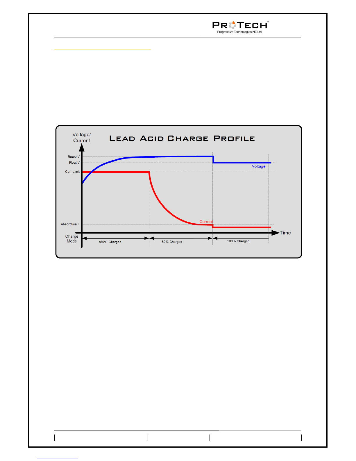
How a Lead Acid Charge Works
The lead acid charging of the ProTechNZ BFS-180 charger is done using a
three stage boost, absorption, float profile. The boost stage brings the
battery stack up to voltage and equalizes the cells in the stack. Once the
boost voltage has been reached, it will go into absorption mode. In this mode
we will wait for the current draw to drop below a specific value. Once that is
reached, we will lower the voltage of the charger to the float voltage, the
charge is then effectively complete and the battery can be left connected
indefinitely as a maintenance charge.
How to Setup a Lead Acid Charge
To set up a Lead Acid charge, you must setup a number of parameters before
you can use the charge profile in the ProTechNZ BFS-180 charger. These
settings can be found in the menu under
Charge Profiles/3St. Lead Acid x/Edit
Settings/.
The ProTechNZ BFS-180 can hold two different Lead Acid profiles.
The menu screens are shown in
Appendix D, Main Menu Screens
, Appendix E,
Charge Profiles Menu Screens and Appendix H, Edit Lead Acid Profile
Screens.
Boost Voltage
This is the voltage we will boost the battery to. A recommended value for
this is 2.4V per cell, or 57.6V for a 48V battery.
Boost Current
The current limit during Boost charging. This value is adjustable from 10A
to 30A. The Current Limit may not be in obtainable if
Power Limits
on page 11
is set lower than the Boost Current required. A recommended value for a
fast charge is C/4 and a regular charge is C/8, where C is the capacity of the
battery stack in Amp Hours.
Absorption End Current
If the battery stack drops below this value, we move into float mode. A
recommended value for this is C/50 where C is the capacity of the battery
stack in Amp Hours.
Page 11

BFS-180
User Manual
Phone: +64 9 818 5115 Page: 11 of 32 Web: www.ProTechNZ.com
Float Voltage
This is the voltage at which we float the battery stack. A recommended value
for this is 2.25V per cell.
Profile Name (optional)
You can name each profile in the ProTechNZ BFS-180 with your own 7
character name. This it to be able to easily select the correct charge profile
when using the ProTechNZ BFS-180 charger on multiple battery stacks.
Maintain Voltage (optional)
The ProTechNZ BFS-180 can automatically restart a charge when the battery
voltage drops below a set voltage. This is suitable for maintaining a battery
stack if it has a load running off the battery during float conditions where
it may flatten the battery. When this is setup, the unit will continuously
monitor the battery after a charge. To cancel this feature temporarily,
simply hold the Back button if the ProTechNZ BFS-180 displays the maintain
battery screen as shown in
Appendix C, Lead Acid Charge Screens
on page 19.
How to Start/Stop a Lead Acid Charge
Starting a Lead Acid charge is done by going into the menu and navigating to
the
Charge Profiles/3St. Lead Acid x/Start Profile
menu. Entering this menu
will start the charge and save the selected profile as its default profile.
The default profile can now be quick started using the Enter and Back
buttons as explained in sections
Starting a Charge
and
Stopping a Charge
under the
User
Interface on page 6.
Power Limits
How Power Limits Work
The power limits are set to limit the amount of power the ProTechNZ BFS-180
draws from the AC mains. This value is not 100% accurate due to the
different efficiency of the charger at different voltages and currents. It is
however perfectly suitable for matching the power consumption to the
capabilities of the mains wiring. There is a power limit that can be set for
both Low Power and High Power. The ProTechNZ BFS-180 automatically
switches from high power to low power depending on what supply it is running
off. If the unit is connected to both supplies it defaults to high power. It
will however fail to low power for safety. This is completely automatic and is
checked during run time as well as on unit boot up.
How to Setup Power Limits
The power limits can be set in the “
Power Limits
” menu of the ProTechNZ BFS-
180 charger which is shown in
Appendix K, Power Limits Screens
on page 26.
There are options to set the Power Limit of both a single phase (Low Power)
and a three phase (High Power) connection. The Power Limits can be set from
300 to 5400 Watts.
Page 12

BFS-180
User Manual
Phone: +64 9 818 5115 Page: 12 of 32 Web: www.ProTechNZ.com
Data Logging
How the Data Logging Works
The Data Logging is a feature that is not fully implemented at this stage. The
Data Logging will currently only be useful for on-site fault finding for a
technician. Users may use the Data Logging feature if they wish but no
information as to what the data represents is provided.
How to Setup the Data Logging
The Data Logging is setup in the “
Data Logging
” part of the menu. The Data
Logging of the ProTechNZ BFS-180 has a few settings that can be changed as
shown in
Appendix J, Data Logging Screens
on page 26.
Enable/Disable Data Logging
Enabling or disabling the Data Logging can be done by selecting this option
from the menu.
Message Rate
This simply sets how often a data packet is sent to the PC/Data Logger. This
is adjustable from one second to ten minutes.
BAUD Rate
The BAUD rate of the RS232 on the ProTechNZ BFS-180 charger can be set
to a range of different settings to make it compatible with virtually any
system.
Page 13

BFS-180
User Manual
Phone: +64 9 818 5115 Page: 13 of 32 Web: www.ProTechNZ.com
Misc Setup
How to Lock/Unlock the System
The system can be locked so that none of the settings are changeable
without unlocking the system with a secure 4 digit password. This is useful if
the charger is to be permanently installed or will be used by non technical
people. To lock or unlock the system, go to “Other Options/Lock Menu” or
“Other Options/Unlock Menu” and enter the password if unlocking the menus.
How to Change the Lock Password
The password default of the ProTechNZ BFS-180 is “1-2-3-4”. To change this,
go to the “
Other Options/Change Password
” menu and enter the old
password, followed by the new one. This is shown in
Appendix O, Other
Options Screens
on page 29.
How Auto Charge Works
The Auto Charge feature allows the charger to start a charge upon power
up. This makes it perfect to charge electric vehicles where the charger is
permanently installed in the vehicle. It is also great for if there is a power
cut and if the charge is interrupted, it will automatically start a new charge
when the power comes back on.
The Auto Charge has a 5 second window where it can be manually concelled
before it connects to the battery. This can easily be canceled by
Stopping a
Charge
as explained on page 7.
How to Enable/Disable the Auto Charge
To enable or disable the auto charge, simply go to the “
Other Options/Charge
on Boot
” menu. In this menu you can enable or disable the auto boot feature.
This is shown in
Appendix O, Other Options Screens
on page 29.
Page 14

BFS-180
User Manual
Phone: +64 9 818 5115 Page: 14 of 32 Web: www.ProTechNZ.com
Trouble Shooting
Error Conditions
The ProTechNZ BFS-180 charger has a number of error conditions that are
checked to ensure safe operation. The error conditions are checked on a
regular basis and the unit will try to rectify the errors when they occur. The
errors are as follows.
Internal Error
An internal error will occur when one of the three internal power modules
fails to respond. When this happens the unit will attempt to reset the power
module to regain control.
Battery Error
A battery error can occur when a battery is either not connected, too low in
voltage, too high in voltage or reverse polarized. When this happens, the
user must check that the battery is connected properly and within 120 and
180 volts before attempting to use the charger.
Settings Reset
This means that the ProTechNZ BFS-180 charger has been reset to its
factory defaults. This happens if the internal memory of the unit has been
compromised. If this happens, contact the manufacturer for further
instructions.
Settings Error
This error occurs when the unit is unable to save your settings to the
internal memory. If this happens, please return the unit back to the
manufacturer for further inspection.
Supply Voltage Error
This is a problem with the AC mains supply to the ProTechNZ BFS-180
charger. Check that all AC mains connections are correct and secure.
Voltage Matching Error
During battery connection and disconnection, the ProTechNZ BFS-180 will
match the voltage of the charger to the voltage of the battery. If the unit is
unable to match to the voltage of the battery to safely connect and
disconnect from the battery stack then this error will appear. If this
happens, turn the unit off at the mains and manually test the battery
voltage to ensure it hasn‟t risen or fallen above or below the 125-179 volt
range that the ProTechNZ BFS-180 will operate at.
Reconnect Error
A reconnect error will occur when there is a problem with the
communications between the control unit and the power modules inside the
ProTechNZ BFS-180 charger. This will occur if there has been an internal
error for five minutes or more. Please stop the charge as explained in the
Stopping a Charge
section on page 7 and send the unit back to the
manufacturer for further inspection.
Retrieving Software Revision Number
When making contact with ProTechNZ about issues with the charger, please
have the software revision number available. To obtain the revision number
and revision date, hold both the Up and Down buttons at the same time and
the revision number and date will appear on the screen, as shown in
Appendix
P, Software Version Screen
on page 29.
Page 15

BFS-180
User Manual
Phone: +64 9 818 5115 Page: 15 of 32 Web: www.ProTechNZ.com
Reprogramming Firmware
Hardware Requirements
1. A fully disconnected BFS-180 charger (located near enough to a
computer to connect a serial cable to the unit)
2. A computer that runs Windows with an available serial port (also
called a COM or RS232 port)
3. A serial cable to connect the 9-pin connector on the ProTechNZ BFS-
180 to the 9-pin serial port connector on the computer (this must be a
'straight through' cable) You will additionally need a number of files as
supplied by ProTechNZ either with the charger or via an online source.
This documentation is written for use on a Windows XP computer. The same
basic process is applicable to other versions of Windows however; please
contact ProTechNZ if you are having trouble getting this to work on another
version.
Preparing the Hardware
- The charger should be fully disconnected, from both mains and the
battery.
- Connect the ProTechNZ BFS-180 charger to the PC using a straight
through serial cable.
- Hold down the Back and Up keys on the ProTechNZ BFS-180 charger
and keep them pressed while turning on the unit.
- When the screen flashes three times in quick succession, turn the unit
back off.
Preparing the PC
- Unzip the supplied files to a handy location (C:\protech\ is
recommended).
- You should now have a folder called 'protech' in C:\ with the following
files in it:
avrdude.conf
avrdude.exe
libusb0.dll
ProgramFirmware.bat
eeprom.eep
flash.hex
- Navigate to the folder and ensure that this is the case.
- The next thing you need to do is determine what COM port the
programming dongle is attached to. Click 'Start' and then right click on
'My Computer'. A drop down menu will appear. Click 'Properties'. In the
dialog box that appears click on the 'Hardware' tab and then click the
'Device Manager' button.
- The device manager will open. To find the list of COM ports in use
expand the 'Ports (COM & LPT)' list by clicking the small '+' sign next to
it. The com port to use will be one of the ones listed here. See the
screenshot in
Appendix Q, Device Manager
on page 30.
- Now open a Command Prompt by clicking 'Start', then click 'Run'. Type
'cmd' in the box that appears. Press 'Enter' or click 'OK'.
- In the Command Prompt type 'cd c:\protech' and press 'Enter'.
- Type 'ProgramFirmware' but do not press enter yet.
Page 16

BFS-180
User Manual
Phone: +64 9 818 5115 Page: 16 of 32 Web: www.ProTechNZ.com
Programming the Firmware
- Hold down the Back and Up buttons of the ProTechNZ BFS-180
charger and apply power. Once the screen flashes three times in quick
succession release the buttons and turn back to the computer.
- Press „Enter‟ to initiate the programming process. You have 10s from
the time the power lead is plugged in to press 'Enter'. Any longer and
the system will time out and programming will not be possible. If this
happens simply unplug the power lead, hold down the buttons and plug
it back in.
- You will be prompted to enter the COM port number that the
ProTechNZ BFS-180 charger is connected to. Enter this (eg. '1') and
press enter. This will start the programming process.
- A number of progress bars will scroll across the screen and
eventually the command prompt will reappear (ie. 'C:\protech>')
- Scroll up through the messages and search for
'XXXX bytes of flash
verified
' and '
XX bytes of eeprom verified
'. This confirms that the
programming has been completed successfully. A sample screen is
provided in
Appendix S, Programming Firmware
on page 31
Page 17

BFS-180
User Manual
Phone: +64 9 818 5115 Page: 17 of 32 Web: www.ProTechNZ.com
Appendix A, Boot Screens
_ _
Page 18

BFS-180
User Manual
Phone: +64 9 818 5115 Page: 18 of 32 Web: www.ProTechNZ.com
Appendix B, Lithium Charge Screens
Page 19

BFS-180
User Manual
Phone: +64 9 818 5115 Page: 19 of 32 Web: www.ProTechNZ.com
Appendix C, Lead Acid Charge Screens
Page 20

BFS-180
User Manual
Phone: +64 9 818 5115 Page: 20 of 32 Web: www.ProTechNZ.com
Appendix D, Main Menu Screens
Page 21

BFS-180
User Manual
Phone: +64 9 818 5115 Page: 21 of 32 Web: www.ProTechNZ.com
Appendix E, Charge Profiles Menu Screens
Page 22

BFS-180
User Manual
Phone: +64 9 818 5115 Page: 22 of 32 Web: www.ProTechNZ.com
Appendix F, Edit Lithium Profile Screens
_
_
_
_
_
_
_
_
Page 23

BFS-180
User Manual
Phone: +64 9 818 5115 Page: 23 of 32 Web: www.ProTechNZ.com
Appendix G, View Lithium Profile Screens
_
_
_
_
_
_
Page 24

BFS-180
User Manual
Phone: +64 9 818 5115 Page: 24 of 32 Web: www.ProTechNZ.com
Appendix H, Edit Lead Acid Profile Screens
_
_
_
_
_
_
_
_
Page 25

BFS-180
User Manual
Phone: +64 9 818 5115 Page: 25 of 32 Web: www.ProTechNZ.com
Appendix I, View Lead Acid Profile Screens
_
_
_
_
_
Page 26

BFS-180
User Manual
Phone: +64 9 818 5115 Page: 26 of 32 Web: www.ProTechNZ.com
Appendix J, Data Logging Screens
Appendix K, Power Limits Screens
Page 27

BFS-180
User Manual
Phone: +64 9 818 5115 Page: 27 of 32 Web: www.ProTechNZ.com
Appendix L, User Interface Screens
Appendix M, Input / Output Screens
Page 28

BFS-180
User Manual
Phone: +64 9 818 5115 Page: 28 of 32 Web: www.ProTechNZ.com
Appendix N, Error Screens
Page 29

BFS-180
User Manual
Phone: +64 9 818 5115 Page: 29 of 32 Web: www.ProTechNZ.com
Appendix O, Other Options Screens
_ _ _
_ _ _
_ _ _
Appendix P, Software Version Screen
Page 30

BFS-180
User Manual
Phone: +64 9 818 5115 Page: 30 of 32 Web: www.ProTechNZ.com
Appendix Q, Device Manager
Appendix R, User Inputs/ Outputs Layout
Page 31

BFS-180
User Manual
Phone: +64 9 818 5115 Page: 31 of 32 Web: www.ProTechNZ.com
Appendix S, Programming Firmware
Microsoft Windows XP [Version 5.1.2600]
(C) Copyright 1985-2001 Microsoft Corp.
C:\Documents and Settings\Cam>cd c:\protech
C:\protech>ProgramFirmware
Please select the COM port number, or enter 'q' to quit [1,2,3,4,5,6,7,8,9,q] 1
avrdude: AVR device initialized and ready to accept instructions
Reading | ################################################## |
100% 0.02s
avrdude: Device signature = 0x1e9508
avrdude: NOTE: FLASH memory has been specified, an erase cycle will be
performed
To disable this feature, specify the -D option.
avrdude: erasing chip
avrdude: reading input file "flash.hex"
avrdude: input file flash.hex auto detected as Intel Hex
avrdude: writing flash (7522 bytes):
Writing | ################################################## |
100% 2.09s
avrdude: 7522 bytes of flash written
avrdude: verifying flash memory against flash.hex:
avrdude: load data flash data from input file flash.hex:
avrdude: input file flash.hex auto detected as Intel Hex
avrdude: input file flash.hex contains 7522 bytes
avrdude: reading on-chip flash data:
Reading | ################################################## |
100% 1.55s
avrdude: verifying ...
avrdude: 7522 bytes of flash verified
avrdude: safemode: Fuses OK
avrdude done. Thank you.
avrdude: AVR device initialized and ready to accept instructions
Reading | ################################################## |
100% 0.02s
avrdude: Device signature = 0x1e9508
Page 32

BFS-180
User Manual
Phone: +64 9 818 5115 Page: 32 of 32 Web: www.ProTechNZ.com
avrdude: reading input file "eeprom.eep"
avrdude: input file eeprom.eep auto detected as Intel Hex
avrdude: writing eeprom (70 bytes):
Writing | ################################################## |
100% 0.28s
avrdude: 70 bytes of eeprom written
avrdude: verifying eeprom memory against eeprom.eep:
avrdude: load data eeprom data from input file eeprom.eep:
avrdude: input file eeprom.eep auto detected as Intel Hex
avrdude: input file eeprom.eep contains 70 bytes
avrdude: reading on-chip eeprom data:
Reading | ################################################## |
100% 0.09s
avrdude: verifying ...
avrdude: 70 bytes of eeprom verified
avrdude: safemode: Fuses OK
avrdude done. Thank you.
C:\protech>
This completes the programming procedure. Unplug the power lead and the
programming dongle. The
charger is now ready to be re-installed in the car.
 Loading...