

Page 1
PROTECH
MODELS COVERED
901
®
INTEGRA III SYSTEM
1/02
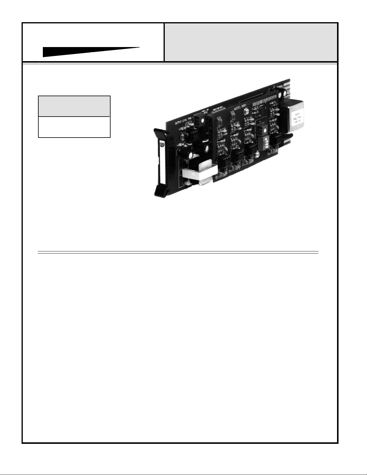
MODEL 901
MODULAR MATRIX MIXING CARD
INSTALLATION & OPERATION MANUAL
Model 901 Shown
www.protechaudio.com
The Model 901 Modular Matrix Mixing Card is
designed for use in professional audio applications. Each
unit features four (4) selectable music inputs, three (3)
paging inputs, one (1) line level output, and a switch
closure circuit for control of priority bypass relays.
Typical applications are public address systems in buildings such as airports, factories, hospitals, courthouses,
casinos, convention centers, libraries, hotels, racetracks,
and office buildings.
The mechanical construction of the Model 901 allows
mounting of up to ten (10) units in a standard Model 857B
Card Frame, or 9 units in a Model 858B Card Frame. Each
Model 901 card unplugs from the front of the card frame,
without the need for removing any wires from the rear of the
card frame. Spare units may be placed into service in a
matter of minutes.
Each Model 901 has four user adjustable features, in
addition to the actual wiring hierarchy. There are two level
adjustments, one for the page output level, and one for the
music output level. There is one four position DIP switch
for selecting any of four music input channels, or no music
input at all. The fourth adjustment is the push-on jumper
which allows public paging to enter a zone.
The Model 901 Modular Matrix Mixing Card is built using two
separate printed circuit board assemblies. The two boards are
connected together using a high quality, gold-plated 15 pin
connector. The main printed circuit board contains all audio
input and output connection points, the page output level
adjustment, the public add enable jumper, and all relay control
circuitry. The smaller printed circuit board is piggy-backed to
the main printed circuit board, and contains all background
music channel circuitry, including the channel selector switch
and the background music level adjusting trimpot.
All integrated circuits used in the Model 901are mounted in
plug-in IC sockets, to facilitate maintenance of the system.The
DC power supply connections are protected by self-resetting
electronic fuses. If a card should malfunction, the electronic
fuses will disconnect the card from the power supply. The
same type of fusing is provided in the priority bypass relay
control circuit.
Other INTEGRA III SYSTEM cards, such as distribution
amplifiers or compressors, may be used in the same card frame
assembly, to allow construction of complete audio systems.
Each of these products is designed to provide the user
with high quality audio, for years of uninterrupted
service.
Protech Audio Corporation, PO Box 597, 192 Cedar River Road, Indian Lake, New York, 12842, Voice 518-648-6410 Fax 518-648-6395
Page 2

INSTALLATION
The Model 901 Modular Matrix Mixing Card is designed
to be mounted in the Model 857B Card Frame, or the Model
858B Card Frame. The Model 857B Card Frame will accomodate
up to 10 audio cards, and requires an external power supply
(Model 66708). The Model 858B Card Frame will accomodate
up to 9 audio cards (depending upon AC current requirements),
and has a built-in, unpluggable power supply card.
All card frame assemblies bus the DC power to the individual
card slots, and provide screw-type barrier termination points for
audio and DC connections.
The determination as to which backplane assembly to use in
your project, was made prior to our factory receiving the
order. The backplane assembly you have received will
accommodate the group of cards you or your designer have
specified.
The actual steps necessary for installation of the
INTEGRA III SYSTEM Modular Matrix Mixing Cards, are
comparable to those necessary for any of the system cards.
They are as follows:
1 - Mount the card frame in an appropriate EIA 19" width
rack, using 4 screws of sufficient tensile strength to provide
secure mounting.
2 - A determination has been made as to which type of power
supply will be used on your system. Follow the instructions
for the type of power supply you will be installing.
4- Unpack each individual card, inspect for shipping
damage, and assuming none is found, slide the card
half-way into the appropriate slot. After all cards have
been installed half-way into the card frame, plug in one card
at a time and turn on the power supply. Make sure no unusual
loading is noticed at the power supply. If loading is noticed,
unplug the card and recheck terminations. If no loading is
noticed, continue inserting each card in the card frame, checking
power supply loading as each card is plugged in. When all the
cards have been plugged in, the installation is complete, and
all that remains is the alignment.
ALIGNMENT
Each Model 901 Modular Matrix Mixing Card with has been
shipped from the factory aligned for unity gain on both the
background music and paging channels. The public page function on the card is active as shipped from the factory. If the
public page is not to be allowed in the zone being set-up,
remove the red push-on jumper located on the lower pc board
assembly. If gain adjustment is required, the following
procedure is recommended:
1-
Remove the Model 901 card from the card slot, and
place a Model 516 extender card in the slot.
2-
Select the background music input to be used by
turning on one of the DIP switch channels on the top
PC board assembly.
3-
Place the Model 901 into the mating connector on
the model 516 extender card.
EXTERNAL POWER SUPPLY. If an external power
supply is to be used, terminate the proper supply
connections to pins 1, 2, & 3 of the 3 pin barrier connector, as
shown in the card frame layout drawing. Turn on the power
supply, and using a DC voltmeter, check for correct voltage and
polarity at pins 1, 2, & 3 of the 3 pin barrier connector.
INTERNAL POWER SUPPLY. If a plug-in power supply
card is to be used, plug in the supply card, , and check for
proper illumination of both DC voltage green LED's.
3 - Terminate all audio input and output connections, using
the card connection drawing on the facing page. Double
conductor shielded cable is recommended for all audio
connections.
4-
Apply background music to the selected channel, and
adjust output level by turning trimpot mounted on the
top pc board assembly.
5-
Actuate any on the 3 paging channel input relays,
apply a signal representative of the page input level
to the selected channel, and adjust the output level
by turning the trimpot mounted on the lower (main)
pc board assembly.
6-
Remove the Model 901 from the Model 516 Extender
card, remove the extender card from the card slot, and
place the Model 9001 into the card slot, making sure it is
seated properly.
This completes the installation and alignment of your
INTEGRA III SYSTEM Modular Matrix Mixing. The cards
may be expected to deliver year of uninterrupted service.
Page 2
Page 3

PROTECH
857B & 858B Backplane Connections
®
INTEGRA III SYSTEM
CONNECTOR DRAWING
Modular Matrix Mixing Card
Model 901
Music 1 Input Hi
Music 1 Input Lo
Music 2 Input Hi
Music 2 Input Lo
Music 3 Input Hi
Music 3 Input Lo
Music 4 Input Hi
Music 4 Input Lo
Code Blue Relay Control
TIC Relay Control
Public Page Relay Control
16
17
18
19
20
21
22
23
24
25
26
27
28
29
30
1
2
3
4
5
6
7
8
9
10
11
12
13
14
15
Public Page Input Hi
Public Page Input Lo
Ground
TIC Input Hi
TIC Input Lo
Code Blue Input Hi
Code Blue Input Lo
Ground
Bypass Relay Control Output
Bypass Relay Control Input
Ground
Zone Output Hi
Zone Output Lo
BACKGROUND MUSIC BOARD
MAIN PAGE BOARD
BACKGROUND MUSIC OUTPUT LEVEL CONTROL
MODEL 901
PAGE OUTPUT
LEVEL CONTROL
- Page 3 -
HIGHER
1
ON
BACKGROUND MUSIC INPUT SELECTOR SWITCH
PUBLIC PAGE ENABLE JUMPER
HIGHER
2
OFF
3
4
Page 4

MODEL 901
MODULAR MATRIX SWITCHING CARD
BLOCK DIAGRAM
MUSIC 1
PINS 18 & 19
MUSIC 2
PINS 20 & 21
MUSIC 3
PINS 22 & 23
MUSIC 4
PINS 24 & 25
PUBLIC PAGE
AUDIO INPUT
PINS 1 & 2
TIC AUDIO
INPUT
PINS 4 & 5
CODE BLUE, ALL CALL &
WIDE AREA AUDIO INPUT
PINS 6 & 7
1
2
3
4
PUBLIC ADD
JUMPER
5
6
7
PUBLIC
PAGING
RELAY
PIN NUMBERS SHOWN ARE CONNECTION
POINTS ON CORRESPONDING MODEL 857B AND 858B
CARD FRAME ASSEMBLYIES
TO PRIORITY
BY-PASS RELAYS
PIN 12
OUTPUT AMPLIFIER
WITH LEVEL
CONTROL
AND TRANSFORMER
LOCAL
TIC
RELAY
CODE BLUE
ALL CALL &
WIDE AREA
RELAY
ISOLATED OUTPUT
PIN 11
PINS
14 & 15
CODE BLUE, ALL CALL &
WIDE AREA RELAY CONTROL
PIN 28
LOCAL TIC
RELAY CONTROL
PIN 29
PUBLIC PAGING
RELAY CONTROL
PIN 30
- Page 4 -
NOTE 1:
THIS CARD TO BE USED IN CONJUNCTION WITH
PRIORITY PAGING SWITCHER CARD.
STANDARD INTEGRA III SYSTEM CARD FRAME
NOTE 2:
MOUNTING.
 Loading...