

Page 1
PROTECH
857B & 858B Backplane Connections
®
1/06
INSTALLATION & OPERATION MANUAL
®
INTEGRA III SYSTEM
REMOTE CONTROLLED AUDIO CARDS
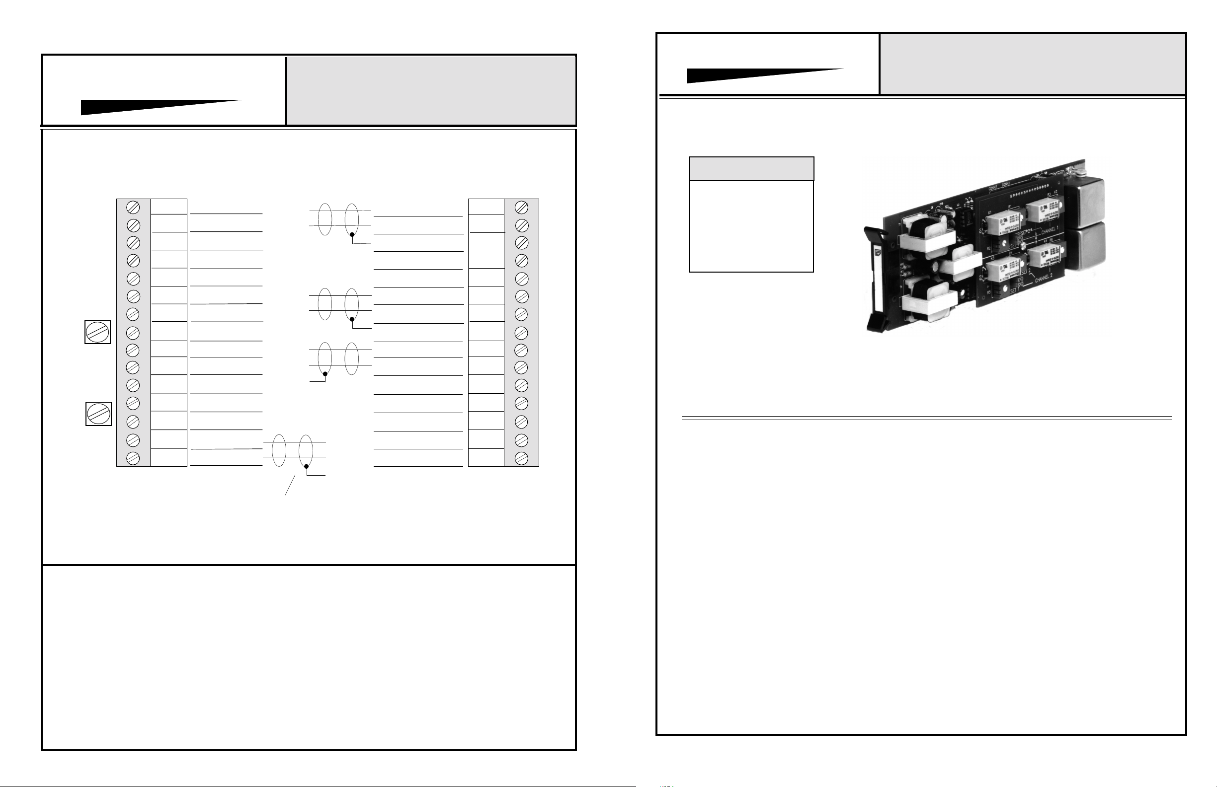
CONNECTOR & TRIMPOT DRAWING
MODELS 892, 893, 894, 896, 897, 898
INTEGRA III SYSTEM
MODELS COVERED
PROTECH
MODEL 891 - 898
CH #1
GAIN
CH #2
GAIN
NOTES:
16
17
18
19
20
21
22
23
24
25
26
27
28
29
30
OUTPUT #1 HI
OUTPUT #1 LO
OUTPUT #2 HI
OUTPUT #2 LO
TYPICAL OF EACH OUTPUT
H
L
H
L
H
L
INPUT #1 HI
INPUT #1 LO
SHIELD
POT #1 ARM
POTS (2) HI
INPUT #2 HI
INPUT #2 LO
SHIELD
SUMMED OUTPUT
HI
SUMMED OUTPUT
LO
1
2
3
4
5
6
7
8
9
10
891
892
893
894
*Microphone Level Inputs
895*
896*
897*
898*
Model 894A Shown
11
LINK OUT
POTS (2) LO
H
L
POT #2 ARM
12
13
14
15
The Models 891 to 898 Remote Controlled Audio Cards are
designed to operate with either microphone or line level
input signals, with remote volume control, and are intended
for use in professional audio systems.
Typical applications are public address systems, courtrooms, sales presentation rooms, headphone listening
systems, and recording systems. The actual application of the
amplifiers is found in buildings such as airports, factories,
courthouses, casinos, convention centers, libraries, hotels,
racetracks, training systems, corporate boardrooms, etc.
The models 891, 892, 893, and 894 have line level inputs.
The models 895, 896, 897, and 898 have microphone
level inputs. All inputs are transformer isolated. The gain of
each input stage is adjustable via a trimpot mounted on the
backplane assembly. The gain adjustment is independent of
the attenuation adjustment.
The attenuation is accomplished using an on-board VCA
(voltage controlled amplifier) circuit in each input section.
The VCA is controlled via a 0-5 volt DC control signal,
generated on-board, which is adjusted by a remotely mounted 10K linear potentiometer. The default for the attenuation
is zero volts = zero attenuation. This default prevents loss of
signal if the control wires are accidentally cut.
www.protechaudio.com
The overall attenuation range of the VCA cards may be
modified in the field, by using a series resistor and changing the
value of the remote potentiometer.
The input sections are followed by a summing amplifier, on
mixing units, and then by a line amplifier circuit (on all models)
depending on the model selected. The output section is
transformer isolated with a high quality, 600 ohm line
transformer.
All units may be linked together to create larger mixing
networks. Both the audio output, and the link output may be
strapped for PRE or POST VCA. This feature allows the audio
output level to be remotely controlled, while the link output is
fed to other units at full volume, or the link output level may be
post VCA while the main output remains at full volume. This
PRE/POST VCA feature is particularly useful when logging
recorders are used.
Both models are designed to mount in the Models 857B or the
858B Card Frame Packages. The all VCA units may be mixed
or matched with other INTEGRA III SYSTEM cards to create
a complete audio system. The Model 858B will allow mounting of 9 cards and an internal power supply. The Model 857B
will allow mounting of up to 10 cards with an external power
supply.
Protech Audio Corporation, PO Box 597, 192 Cedar River Road, Indian Lake, New York, 12842, Voice 518-648-6410 Fax 518-648-6395
Page 2
INSTALLATION
The Models 891 - 898 Remote Controlled Audio Cards are
designed to be mounted in the Models 858B Card Frame
Package or the Model 857B Card Frame Package. The
Model 858B will hold up to 9 cards and an internal power
supply. The Model 857B will hold up to 10 cards with an
external power supply.
3- Terminate all audio input and output connections, using
the card connection drawing on the facing page. Double
conductor shielded cable is recommended for all audio
connections.
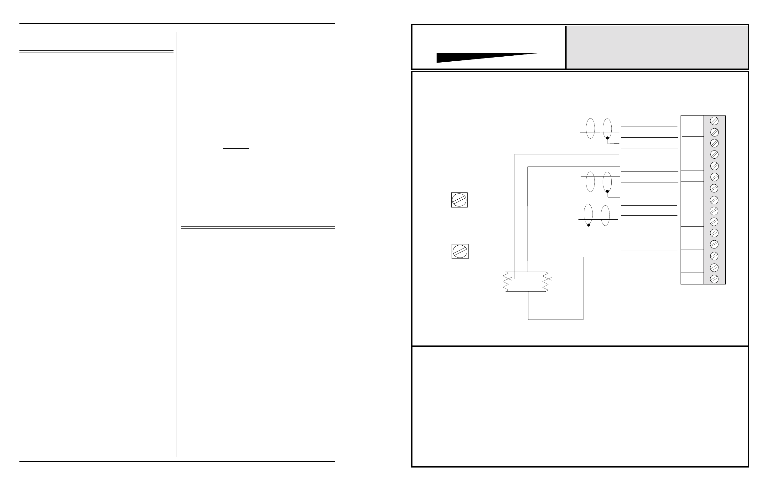
4- Terminate the remote potentiometer leads as shown on
the facing page. If a restricted attenuation range is
desired, install selected resistor in series with potentiometer LO connection, and use potentiometer value as shown
on facing page.
PROTECH
®
CONNECTOR & TRIMPOT DRAWING
INTEGRA III SYSTEM
MODEL 891 & 895
857B & 858B Backplane Connections
The backplane assemblies bus the DC power to the
individual card slots, and provide screw-type barrier termination points for audio and DC connections. They also
allow mounting of the gain control trimpots.
The determination as to which backplane assembly to use
in your project, was made prior to our factory receiving the
order. The backplane assembly you have received will
accommodate the group of cards you or your designer
have specified.
The actual steps necessary for installation of the
Remote Control Audio Cards 891 and 895 are
comparable to those necessary for any of the
INTEGRA III SYSTEM cards. They are as follows:
1- Mount the card frame in an appropriate EIA 19" width
rack, using 4 screws of sufficient strength to provide
secure mounting.
2- A determination has been made as to which type of
power supply will be used on your system. Follow the
instructions for the type of power supply you will be
installing.
EXTERNAL POWER SUPPLY. If an external power
supply is to be used, terminate the proper supply
connections to pins 1, 2, & 3 of the 3 pin barrier connector
on the left hand side of the backplane assembly. Turn on
the power supply, and using a DC voltmeter, check for
correct voltage and polarity at pins 1, 2, & 3 of the barrier
connector.
INTERNAL POWER SUPPLY. If a plug-in power supply
card is to be used, plug in the supply card, and observe the
two green LED's for proper illumination.
5- Unpack each individual card, inspect for shipping
damage, and assuming none is found, slide the
card
half-way into the appropriate slot. After all cards have
been installed half-way into the card frame, plug in one
card at a time and turn on the power supply. Make sure no
unusual loading is indicated at the power supply . If
loading is noticed, turn off the power supply, unplug the
card and recheck terminations. If no loading is noticed,
continue inserting each card in the card frame, checking
power supply loading as each card is plugged in. When all
the cards have been plugged in, the installation is
complete, and all that remains is the alignment.
ALIGNMENT
Each line level card has been shipped from the factory
with the gain trimpot installed in the backplane , and
aligned for unity gain. Each microphone level card has
been shipped with the gain trimpot installed in the
backplane, and aligned for 45 dB of Gain.
This alignment level helps prevent overload upon initial
system turn-on, and maximizes headroom. If additional
gain is required, the following alignment procedure
is recommended;
1- Turn the remote control pots to the minimum attenuation position.
2- Apply a signal representative of the actual signal level
to be used, to input #1.
3- While monitoring the output, turn the input #1gain
trimpot, mounted on the backplane assembly, until the
output signal reaches the desired level.
4- Repeat steps 1 to 3 for input channel #2.
Note #1The alignment procedures for INTEGRA III SYSTEM
Cards, differ from card type to card type. Therefore it is
necessary to consult the alignment procedure for each
type of card being installed, to properly align a card frame
using fifferent card types.
NOTES:
CH #1
GAIN
CH #2
GAIN
H
L
H
L
H
L
INPUT #1 HI
INPUT #1 LO
SHIELD
POT #1 ARM
POTS (2) HI
INPUT #2 HI
INPUT #2 LO
SHIELD
OUTPUT HI
OUTPUT LO
1
2
3
4
5
6
7
8
9
10
11
LINK OUT
POTS (2) LO
POT #2 ARM
LINK IN
12
13
14
15
Page 2
 Loading...