

Page 1

PROTECH
MODELS COVERED
®
1/02
LIMITER/PREAMPLIFIERS & LINE AMPLIFIERS
INSTALLATION & OPERATION MANUAL
INTEGRA III SYSTEM
INTEGRA III SYSTEM
800 SERIES
822B
823B
824B*
*Microphone Preamplifier
830B
831B
832B*
www.protechaudio.com
www.protechaudio.com
The 800 Series Limiter/Preamplifier and Line Amplifiers are designed for use in professional audio
appplications. Each model has either one or two
channels, designed to operate as a discrete microphone preamplifier or line amplifier. Dual channel
cards will have two identical channels constructed on
one printed circuit board.
Typical applications a r e public address systems,
broadcast studios, sales presentation rooms
headphone listening systems, multi-room audio
systems, and recording systems. The actual
application of the amplifiers is found in buildings
such as airports, factories, courthouses, casinos,
convention centers, libraries, hotels, racetracks, training systems, corporate boardrooms, etc...
The 800 Series Limiter/Preamplifiers come in two
different models. There is a single channel model,
and a dual channel model. Both models have low
impedance transformer isolated inputs. The gain of
each model is adjustable, via trimpots mounted on
the backplane assembly, from 17 to 56dB. The
output section is available in either unbalanced
direct, or balanced transformer isolated versions.
Model 832B Shown
The 800 Series Limiter/Line Amplifiers offer 4 different models, 2 single channel versions, and 2 dual
channel versions.
The input section of the line amplifiers is available in
two different impedances. They are; bridging
balanced-transformer isolated, and 600 Ohm
balanced-transformer isolated. This allows the user
to match the line amplifiers to a variety of
professional audio equipment.
The trimpots used to adjust the gain levels and the
threshold of limiting, are mounted on the backplane
assembly. This feature allows replacement of a card,
without the need to readjust gains and thresholds.
The limiting ratio is 40:1. The output section of the
line amplifiers is balanced transformer. On page 3 of
this manual, you will find a table showing the model
numbers, and features of each of the microphone
preamplifier/limiters, and the line amplifier/limiters.
Each of these products is designed to provide the
user with high quality audio, for years of
uninterrupted service.
Protech Audio Corporation, PO Box 597, 192 Cedar River Road, Indian Lake, New York, 12842, Voice 518-648-6410 Fax 518-648-6395
Page 2
INSTALLATION
The 800 Series Limiter/Preamplifiers and Limiter/Line
Amplifiers are designed to be mounted in the Model 857B Card
Frame Package or the Model 858B Card Frame Package. The
Model 857B Card Frame Package will accomodate up to 10
audio cards, and requires an external power supply, Model
66708.
The Model 858B Card Frame Package will accomodate up to 9
audio cards, and has a built-in, unpluggable power supply card.
Both card frame assemblies buss the DC power to the individual
card slots, and provide screw-type barrier termination points for
audio and DC connections.
After receiving an order for 800 audio cards, and prior to
shipping the order, the factory has requested from you or
your firm, a card file layout sketch. Using this drawing, the
factory has mounted the necessary trimpots in the backplane
assembly. This service allows the factory to test each card
in the card frame assembly, and saves the installer time when
assembling the complete audio system. Also, the installer can
be confident that each card received has been tested in the
actual slot used.
The actual steps necessary for installation of the 800 Series
Microphone Preamplifier/Limiter and Line Amplifier/Limiter
cards, are comparable to those necessary for any of the 800
series cards. They are as follows:
1- Mount the card frame in an appropriate EIA 19" width rack,
using 4 screws of sufficient tensile strength to provide secure
mounting.
2- A determination has been made as to which type of power
supply will be used on your system. Follow the instructions for
the type of power supply you will be installing.
EXTERNAL POWER SUPPLY. If an external power supply
is to be used, terminate the proper supply connections to
pins 1, 2, & 3 of the DC barrier connector, as shown in the card
frame layout drawing. Turn on the power supply, and using
a DC voltmeter, check for correct voltage and polarity at pins 1,
2, & 3 of the barrier connector.
INTERNAL POWER SUPPLY. If a plug-in power supply card
is to be used, plug in the supply card, turn it on, and check for
proper illumination of the positive and negative voltage LED's,
on the front of the power supply card.
3- Terminate all audio input and output connections, using
the card connection drawing on page 3. Double conductor
shielded cable is recommended for all audio connections.
Terminate each unused input with a 1K ohm resistor.
4- Unpack each individual card, inspect for shipping
damage, and assuming none is found, slide the card
half-way into the appropriate slot. After all cards have been
installed half-way into the card frame, plug in one card at a time
and turn on the power supply. Make sure no unusual loading is
noticed at the power supply. If loading is noticed, turn off the
power supply, unplug the card and recheck terminations. If no
loading is noticed, continue inserting each card in the card
frame, checking power supply loading as each card is plugged
in. When all the cards have been plugged in, the installation is
complete, and all that remains is the alignment.
ALIGNMENT
Each 800 Series card with microphone level inputs has been
shipped from the factory aligned for 45dB of gain. Each Line
Amplifier card has been shipped with the gain set for unity. The
threshold of limiting is set to 0dB on all limiter cards. This
alignment optimizes headroom. If additional gain is required,
the following alignment procedure is recommended;
1 - Turn all threshold trimpots fully clockwise.
2 - Apply a signal representative of the actual signal level to be
used, to channel #1.
3 - While monitoring the output channel, turn the output
gain trimpot until the output signal
reaches the desired level.
4 - Increase the audio input 5dB. Turn the threshold
trimpot counterclockwise until the output level returns to the
original setting.
5 - Decrease the input level 5dB and check to make sure the
output returns to the original level.
6 - Repeat steps 1 thru 5 for each channel on your
preamplifier or line amplifier.
This completes the installation and alignment of your 800 Series
Limiter/Preamplifiers and Line Amplifiers. The cards may be
expected to deliver years of uninterrupted service.
Note 1The alignment procedures for 800 Series cards, differ from
card type to card type. Therefore it is necessary to consult the
alignment procedure for each type of card being installed, to
properly align a card frame using different card types.
Note 2- The levels mentioned in the alignment procedure are
used for demonstration purose only. Only the factory adjusted
levels prior to shipment are actual. The installer may use
whatever levels are necessary, as long as they are within the
specified parameters on the type of card used, as defined in the
product specifications.
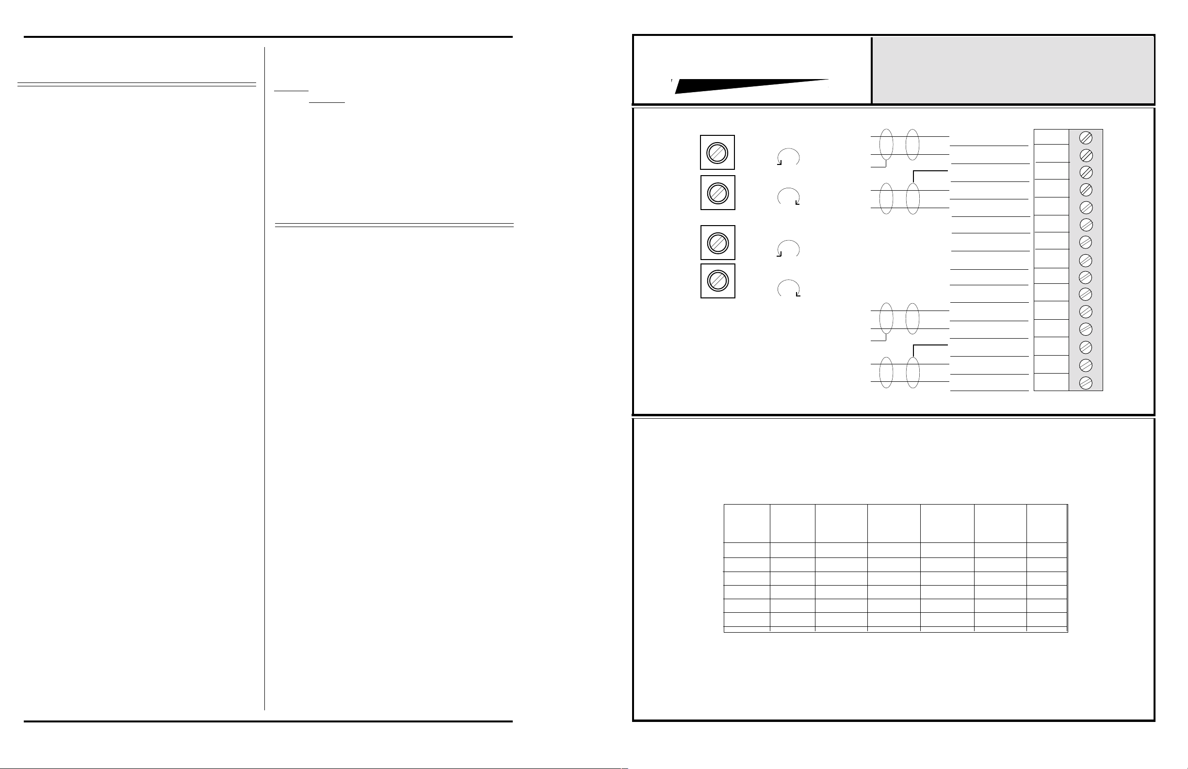
PROTECH
THRESHOLD CHANNEL #1
LOWER
CCW
GAIN CHANNEL #1
MORE
CW
THRESHOLD CHANNEL #2
LOWER
CCW
GAIN CHANNEL #2
MORE
CW
Model
Number
822B
823B
824B
830B
831B
832B
Channels
1
1
1
2
2
2
®
600 Ohm
Transformer
Input
*
*
H
L
H
L
H
L
H
L
10K Ohm
Transformer
Input
*
*
INTEGRA III SYSTEM
CONNECTOR & TRIMPOT DRAWING
MODELS 822B-832B
USING 857B & 858B BACKPLANES
INPUT #1 HI
INPUT #1 LO
GROUND
OUTPUT #1
OUTPUT #1 LO
HI
1
2
3
4
5
6
7
GROUND
8
9
10
INPUT #2 HI
INPUT #2 LO
GROUND
OUTPUT #2 HI
OUTPUT #2 LO
150 Ohm
Transformer
Input
*
*
17-56dB
Gain
*
*
11
12
13
14
15
-10 To
25dB
Gain
*
*
*
*
Page 2
 Loading...