

Page 1
PROTECH
MODELS COVERED
704-IN
704-OP
®
3/02
INTEGRA III SYSTEM
Modular Matrix Mixer
INSTALLATION & OPERATION MANUAL
www.protechaudio.com
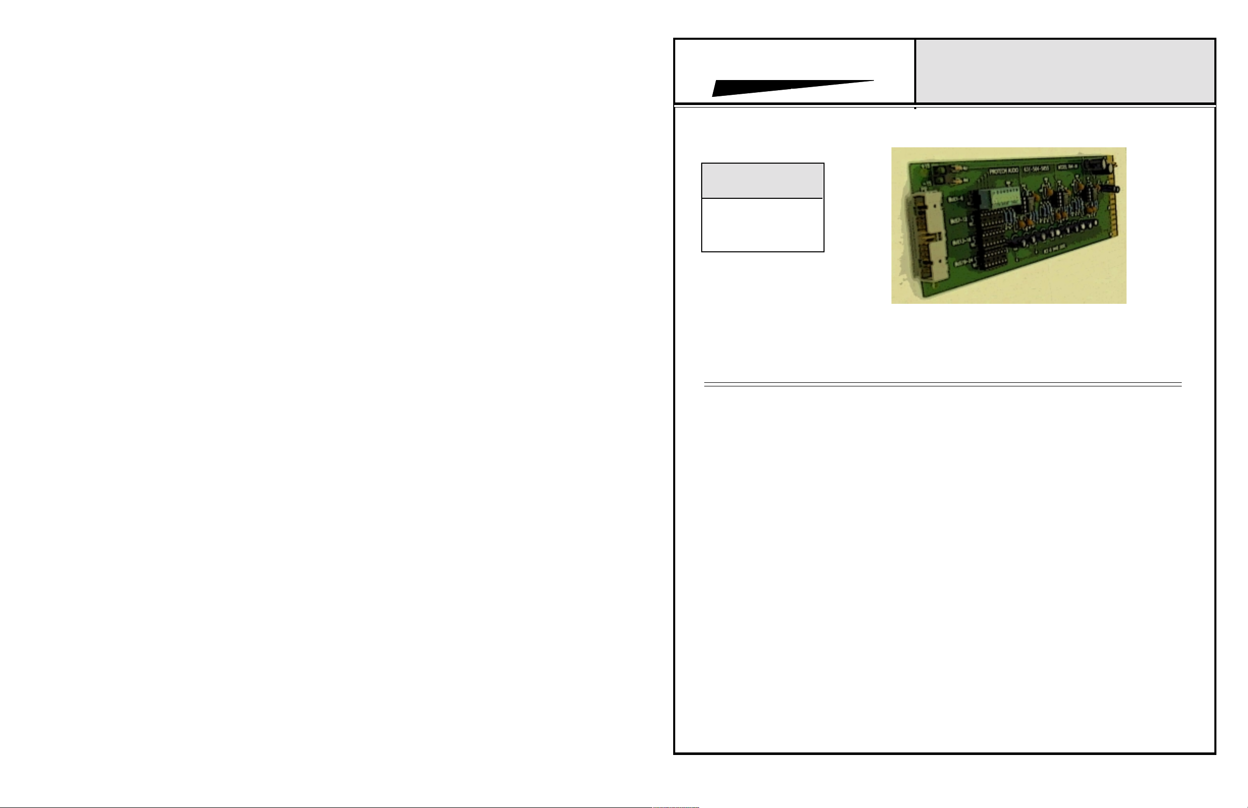
The Models 704-IN and 704-OP Modular Matrix
Mixers are designed to provide low cost, incremental matrix mixing of audio signals in professional,
fixed installations.
Inputs can be added, in increments of 6, up to a
maximum of 24 (Model 704-IN). Outputs can be
added, in increments of 6, up to a maximum of
36 (Model 704-OP).
The design o f t h e Model 704 is elegantly s i m p le.
Input circuits buffer the incoming signal, and pass
the signal thru to a series of summing amplifiers.
Each input may be assigned, via on-board DIP
switches, to any or all summing amplifiers. Each
summing amplifier will accept up to 24 separate,
line level signals.
Matrixes, from as small as 6 x 6, all the way up
to 24 x 36, may be created. Other switching cards
in the INTEGRA III SYSTEM, for example the
Model 703-4 Remote Push-Button Program Selector
and Volume Control, may be used to remotely select
between custom matrix outputs.
Inputs may be used in balanced or unbalanced
configuration. Outputs may be used in balanced or
unbalanced configuration. Selection of balanced or
unbalanced operation of outputs, is made via pushon jumpers.
A 26 pin ribbon cable straps input and output cards
together, on the front edge, to complete the matrix
assembly.
Each module is individually fused, with auto-resetting electronic fuses. In the event of a component
failure, the module will remove itself from the power
supply bus, allowing the remainder of the system
to continue operating
As one of the INTEGRA III SYSTEM cards,
the Model 704 Modular Matrix Mixer cards may
be mounted in any of the system enclosures
manufactured by P rotech Audio. Th e Mo del 858B
Card Frame allows mounting of up to 9 cards
in just 3.5" of vertical rack space. The Model
857B Card Frame allows mounting of 10 cards in
the same rack space, and requires an external
power supply (Model 66708). The Model 704
Modular Matrix Mixers may be mixed and
matched with other INTEGRA III SYSTEM cards
within the same card frame.
For additional information contact:
APPLICATIONS ASSISTANCE
Protech Audio Corporation, PO Box 597, 192 Cedar River Road, Indian Lake, New York, 12842, Voice 518-648-6410 Fax 518-648-6395
Page 2

INSTALLATION
The Model 704 cards are designed to be mounted in the
Models 857B or 858B Card Frame Assemblies. The Model
857B will accomodate up to 10 audio cards, using an
external power supply (Model 66708), and the Model 858B
will accomodate or up to 9 audio cards, and uses a plug in power supply card The power supply card used in the
Model 858B card frame assembly is designed to deliver
600ma of power to a card frame.
The actual steps necessary for installation of the Modular
Matrix Mixer cards, are comparable to those necessary for any
of the Integra III System cards, with the exception of the linking
ribbon cable. They are as follows;
1- Mount the card frame in an appropriate EIA 19" width
rack, using 4 screws of sufficient strength to provide
secure mounting.
2- A determination has been made as to which type of power
supply will be used on your system. Follow the instructions for
the type of power supply you will be installing.
EXTERNAL POWERED CARD FRAME Model 857B.
If an external power supply (Model 66708) is being used,
terminate the supply connections to pins 1, 2, & 3 of the
DC barrier connector, as shown in the card frame layout
drawing, and the Model 66708 Installation and Operation
Manual. Turn on the power supply, and using a DC
voltmeter, check for correct voltage and polarity at pins 1,
2, & 3 of the DC barrier connector.
INTERNALLY POWERED CARD FRAME Model 858B
Plug in the external power transformer, and connect to card
frame. Plug in the power supply card, , and check for proper
illumination of both the positive and negative voltage LED's, on
the front of the power supply card.
3- Terminate all audio input and output connections, using the
card connection drawing on the facing page. Double conductor
shielded cable is recommended for all audio connections.
Output connections should be made using 22AWG wire or
heavier.
4- Unpack each individual card, inspect for shipping
damage, and assuming none is found, slide the card
half-way into the appropriate slot. After all cards have been
installed half-way into the card frame, plug in one card at a time
and turn on the power supply. Make sure no unusual loading is
indicated at the power supply . If loading is noticed, turn off
the power supply, unplug the card and recheck terminations.
If no loading is noticed, continue inserting each card in the card
frame, checking power supply loading as each card is plugged
in. When all the cards have been plugged in, the installation
is complete, and all that
remains is the alignment.
ALIGNMENT
Each Modular Matrix Mixer card has been shipped from the
factory set for balanced line operation. If unbalanced operation
is desired, move red push-on jumpers on output cards.
1- On the input cards, place the bus selector DIP switch into the
desired bus group IC socket.
2- On the output cards, select inputs to appear on each output by
selecting that channel on the 8 position DIP switches.
3- On the output cards, if unbalanced operation is desired,
move the red push-on jumpers, over one pin.
4- Place the ribbon cable/connector assembly onto the front of
all Modular Matrix Mixer cards in the system.
This completes the installation and alignment of your Modular
Matrix Mixer Cards. The mixers may be expected to deliver
years of uninterrupted service.
Page 2
3/02
Page 3

PROTECH AUDIO
®
INTEGRA III SYSTEM
CONNECTOR & TRIMPOT DRAWING
MODEL 704-CA Link Cable
I
N
P
U
T
I
N
P
U
T
O
U
T
P
U
T
O
U
T
P
U
T
Drawing shows 12 x 12 system. Link cable simply pushes onto front of
input and output cards, after DIP switches and balanced/unbalanced
jumpers have been set.
Factory provides exact cable length for the system ordered (6 x 6, 12 x
12, etc.).
Page 4

PROTECH AUDIO
®
CONNECTOR & TRIMPOT DRAWING
INTEGRA III SYSTEM
PROTECH AUDIO
®
CONNECTOR & TRIMPOT DRAWING
MODEL 704-IN Input Card
INTEGRA III SYSTEM
MODEL 704-OP Output Card
Models 857B, & 858B Backplane Connections
L
H
L
H
L
H
L
H
L
H
L
H
INPUT #1 LO
INPUT #1 HI
SHIELD
INPUT #2 LO
INPUT #2 HI
INPUT #3 LO
INPUT #3 HI
SHIELD
INPUT #4 LO
INPUT #4 HI
INPUT #5 LO
INPUT #5 HI
SHIELD
INPUT #6 LO
INPUT #6 HI
1
2
3
4
5
6
7
8
9
10
11
12
13
14
15
Models 857B, & 858B Backplane Connections
L
H
L
H
L
H
L
H
L
H
L
H
OUTPUT #1 LO
OUTPUT #1
HI
SHIELD
OUTPUT #2 LO
OUTPUT #2
HI
OUTPUT #3 LO
OUTPUT #3
HI
SHIELD
OUTPUT #4 LO
OUTPUT #4
HI
OUTPUT #5 LO
OUTPUT #5
HI
SHIELD
OUTPUT #6 LO
OUTPUT #6
HI
1
2
3
4
5
6
7
8
9
10
11
12
13
14
15
Ribbon Cable
Connector
DIP Switch
BUS1-6
BUS7-12
BUS13-18
BUS19-24
IC Sockets
Placing DIP Switch in IC Socket Selects
Bus Assignment.
Only One Input Card Can Be Assigned To
Each Bus Group.
Ribbon Cable
Connector
Output 1
Output 2
Output 3
Channel Selection
DIP Switches
Output 4
Output 5
Output 6
BAL = Balanced Output
UNB = Unbalanced Output
Jumper between top and middle pin for balanced
output.
Jumper between middle pin and bottom pin for
unbalanced output.
 Loading...