

Page 1
PROTECH
MODELS COVERED
702-LL
702-ML
702-MM
®
1/06
INTEGRA III SYSTEM
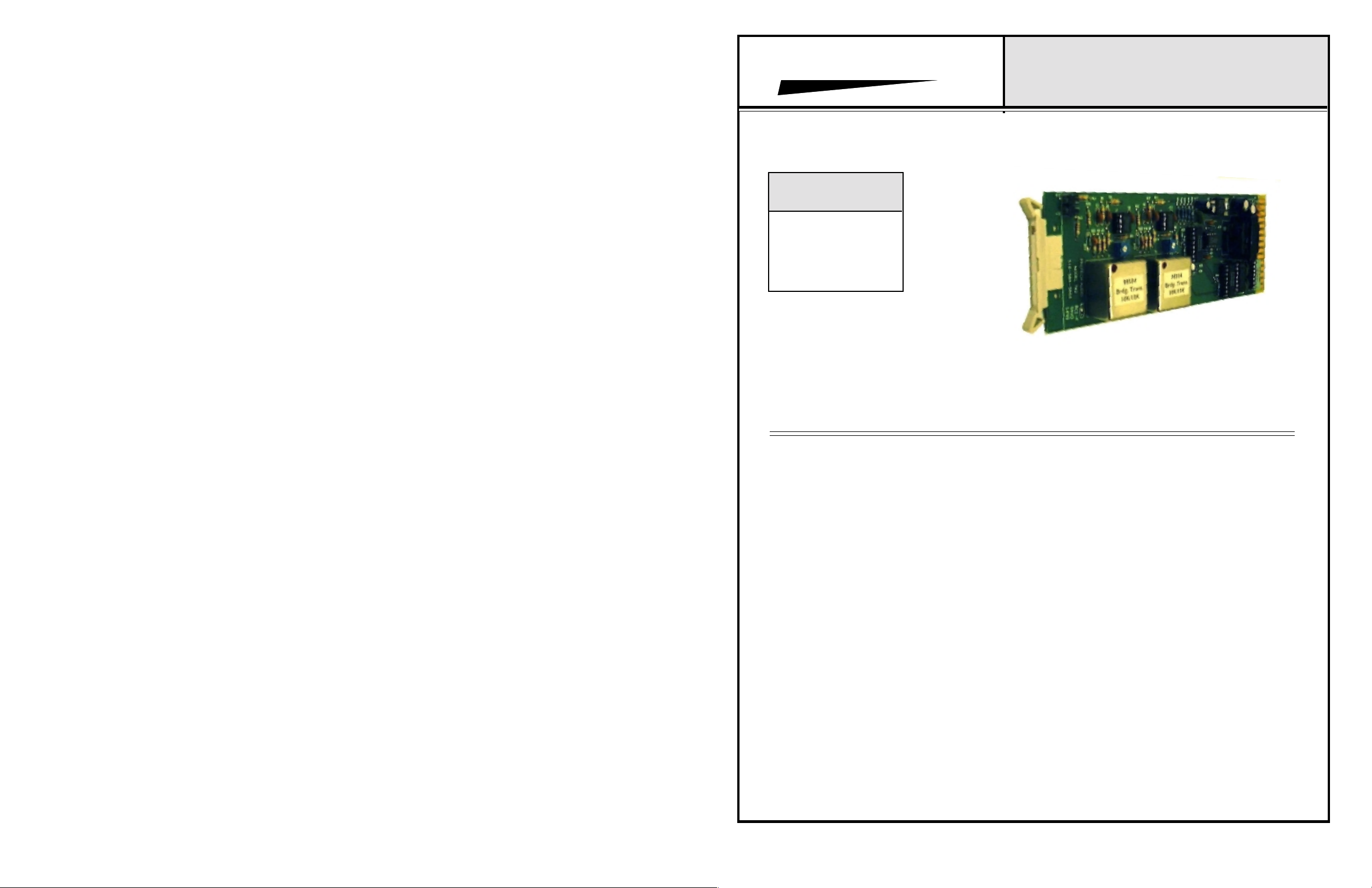
Switchable Input Mixer Cards
INSTALLATION & OPERATION MANUAL
INTEGRA III SYSTEM
Model 702-LL Shown
www.protechaudio.com
The Protech Audio Switchable Input Mixer cards
are designed for use by audio professionals.
Each unit is carefully designed and constructed
to provide highly reliable, quiet switching of
audio signals to an on-board output, and a link
output. The unit may be used to control paging
systems, provide signal routing in broadcast
facilities, or sound system configuration in live
venues.
All 3 models are configured as a two input
mixer cards. Different input combinations (mic
or line) are available as follows;
Model 702LL = 2 Line Inputs.
Model 702ML = 1 Mic Input, 1 Line Input.
Model 702MM = 2 Mic Inputs.
The Model 702 cards are linkable, allowing larger
systems to be configured. By applying ground
to the individual channel control pins, each input
channel may be assigned to the on-board
output, or the link out. The on-board output is
balanced, transformer-isolated. The output is
designed to drive 600-15K ohm loads.
The link output for each input channel has a
separate switch from the on-board output switch.
This feature allows the input channel signal to
be assigned to the link output, or the on-board
output, separately.
The gain of each input channel is adjustable,
via on-board, or backplane mounted trimpots. For
backplane mounted trimpots, simply add the suffix
"BP" to the part number (see back page of this
sheet for additional part number information).
As one of the INTEGRA III SYSTEM modules, the
Mod el 70 2 Mix er ca rds ma y b e m ounte d i n a ny
of the system enclosures manufactured by
Protech Audio. The Model 858B Card Frame
Package will allow up to 9 plug-in cards plus a
plug-in power supply, in just 3.5" of vertical rack
space. The Model 857B allows mounting of up to
10 cards in 3.5" of rack space, and requires an
external power supply (Model 66708).
For additional information, or applications
assistance, contact:
SALES-ENGINEERING
Protech Audio Corporation, PO Box 597, 192 Cedar River Road, Indian Lake, New York, 12842, Voice 518-648-6410 Fax 518-648-6395
Page 2
INSTALLATION
The Model 702 cards are designed to be mounted in
the Models 857B or 858B Card Frame Assemblies. The
Model 857B will accomodate up to 10 audio cards,
using an external power supply (Model 66708), and the
Model 858B will accomodate or up to 9 audio cards,
and uses a plug-in power supply card The power
supply card used in the Model 858B card frame
assembly is designed to deliver 600ma of power to
a card frame.
The actual steps necessary for installation of the
Switchable Input Mixer cards, are comparable to those
necessary for any of the Integra III System cards. They are
as follows;
1- Mount the card frame in an appropriate EIA 19" width
rack, using 4 screws of sufficient strength to
provide secure mounting.
2- A determination has been made as to which type of
power supply will be used on your system. Follow the
instructions for the type of power supply you will be
installing.
EXTERNAL POWERED CARD FRAME Model 857B.
If an external power supply (Model 66708) is being used,
terminate the supply connections to pins 1, 2, & 3 of
the DC barrier connector, as shown in the card frame
layout drawing, and the Model 66708 Installation and
Operation Manual. Turn on the power supply, and
using a DC voltmeter, check for correct voltage and
polarity at pins 1, 2, & 3 of the DC barrier connector.
INTERNALLY POWERED CARD FRAME Model 858B
Plug in the external power transformer, and connect to
card frame. Plug in the powersupply card, , and check for
proper illumination of both the positive and negative voltage LED's, on the front of the power supply card.
3- Terminate all audio input and output connections, using
the card connection drawing on the facing page. Double
conductor shielded cable is recommended for all audio
connections. Output connections should be made using
22AWG wire or heavier.
4- Unpack each individual card, inspect for shipping
damage, and assuming none is found, slide the
card
half-way into the appropriate slot. After all cards have
been installed half-way into the card frame, plug in one
card at a time and turn on the power supply. Make sure no
unusual loading is indicated at the power supply . If
loading is noticed, turn off the power supply, unplug the
card and recheck terminations. If no loading is noticed,
continue inserting each card in the card frame, checking
power supply loading as each card is plugged in. When all
the cards have been plugged in, the installation is
complete, and all that
remains is the alignment.
ALIGNMENT
Each Switchable Mixer card has been shipped from the
factory aligned for unity gain on line inputs, and 45dB of
gain on microphone inputs. This alignment level helps
expedite setup. If additional adjustments are required,
the following alignment procedure is recommended;
1- Apply a signal representative of the actual signal level
to be used, to the input.
2- Ground the control pin for the channel being aligned,
and while monitoring the output level, turn the channel
trimpot until the desired level is achieved.
3- Repeat step #2 for each input in your system.
This completes the installation and alignment of your
Switchable Input Mixer Cards. The mixers may be expected to deliver years of uninterrupted service.
PROTECH AUDIO
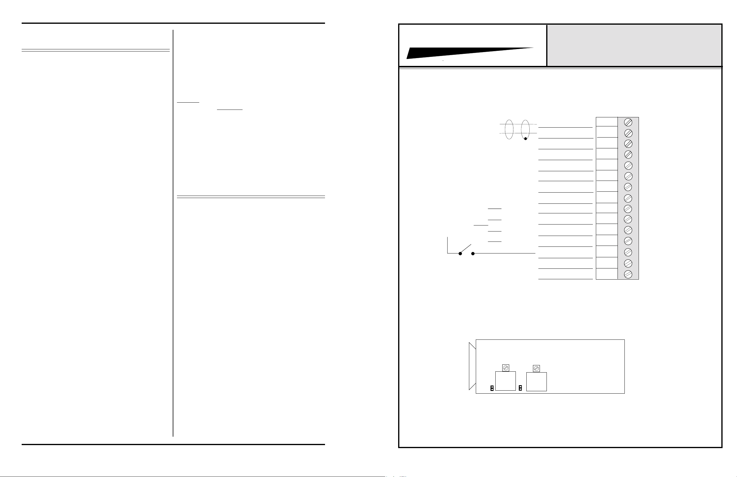
857B & 858B Backplane Connections
L
H
CONTROL, CHANNEL 1 TO OUT-
GROUNDING
CONTROL PINS
ACTIVATES
CHANNEL "ON".
EXTERNAL SWITCHES ONE PER CONTROL PIN, OR
ONE COMMON SWITCH.
Model 702LL = 2 line inputs.
Model 702ML = Channel 1 Line, Channel 2 Microphone
Model 702MM = 2 Microphone Inputs
PUT
CONTROL, CHANNEL 2 TO OUT-
PUT
CONTROL, CHANNEL 1 TO LINK
OUT
CONTROL, CHANNEL 2 TO LINK
OUT
®
OUTPUT LO
OUTPUT HI
SHIELD
INPUT #1 HI
INPUT #1 LO
INPUT #2 HI
INPUT #2 LO
GROUND
GROUND
LINK OUT
LINK IN
INTEGRA III SYSTEM
CONNECTOR & TRIMPOT DRAWING
MODELS 702LL, 702ML,
702MM
1
2
3
4
5
6
7
8
9
10
11
12
13
14
15
Note #1The alignment procedures differ from card type to card
type. Therefore it is necessary to consult the alignment
procedure for each type of card being installed, to properly
align a card frame using fifferent card types.
Page 2
GAIN
CHANNEL
1
JP1
JP1 & JP2 PHANTOM POWER JUMPERS ON MODELS 702ML (JP2) &
702MM (JP 1 & JP2).
GAIN
CHANNEL 2
JP2
 Loading...