

Page 1
PROTECH
®
1/06
685
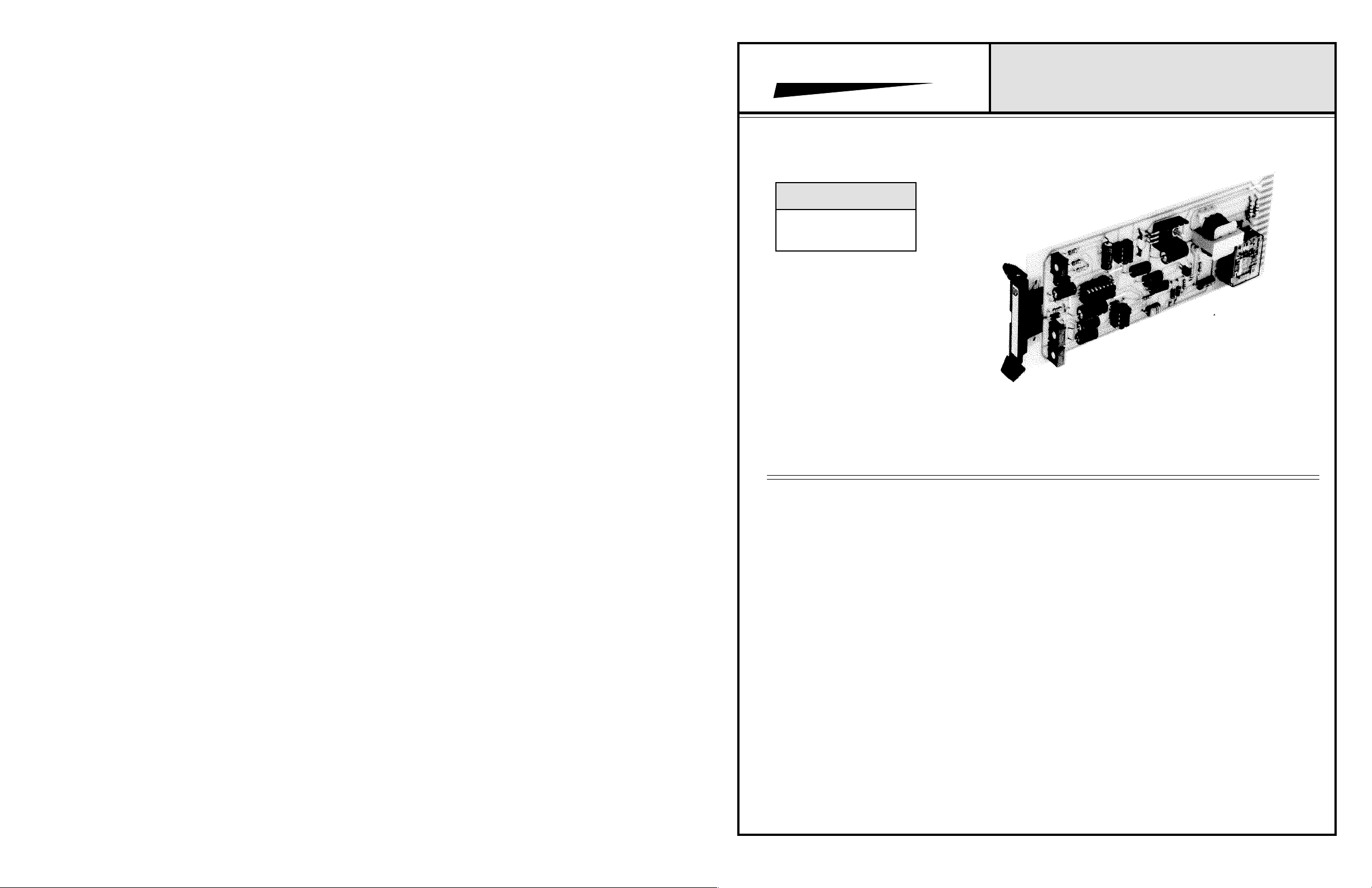
TONE SUPERVISOR CARD
INSTALLATION & OPERATION MANUAL
MODEL COVERED
INTEGRA III SYSTEM
685
www.protechaudio.com
The Model 68 5 Tone Supervisor Card is designed
for use in professional audio applications, which
require constant, automatic supervision of audio
equipment.
The card detects the presence of a 25Hz signal, even
when program material is present. The 25Hz signal may
be fed into the audio signal path at any point
in the system. There are INTEGRA III SYSTEM
cards available to help facilitate the mixing of the
supervisory tone into the audio system. Feeding the
supervisory tone into the audio system at the earliest
possible point, will allow the supervisor card to
monitor the operation of more equipment.
The Tone Supervisor card is capable of monitoring
audio circuits from 600 ohms to 70 volt distributed
systems. The input of the card is balanced, bridging,
transformer isolated.
Typical applications are multi-zone public address
systems, intercoms, paging systems, training systems,
and monitoring systems. The actural application is
found in buildings such as airports, factories,
courthouses, casinos, convention centers, libraries,
military facilities, racetracks, and corporate boardrooms.
Model 685 Shown
The Model 685 features a transformer isolated input,
in order to allow the unit to be connected to circuits w i t h o u t
unbalancing the line. One set of input pins is used for line
level circuits, while another set is used for 25 and 70 volt
distributed audio speaker lines.
The audio is fed from the secondary of the input
transformer to a tuned detector circuit. The detector
circuit is tuned to react to a 25Hz, constant magnitude
tone. When the circuit detects the presence of this tone,
it turns on the on-board relay. If the tone should drop in
level, or completely disappear, the detector circuit turns
off the relay.
The on-board relay contacts are wired, by the installer, to
a remote annunciator panel. This panel usually contains
LED indicators, to alert personnel of a circuit failure. The
relay contacts may be wired to several remote annunciator
panels if necessary. The relay contains an adjustable dropout delay, to prevent nuisance tripping.
The Model 517 25Hz Notch Filter may be used in
conjunction with the Model 685, to process program
material, and remove any 25Hz content. For more
information, contact: SALES ENGINEERING
Protech Audio Corp., 192 Cedar River Road, Indian Lake, New York 12842 Voice 518-648-6410 Fax 518-648-6395
Page 2
INSTALLATION
The Model 685 Tone Supervisor Card is designed to
be mounted in the Model 857B Card Frame, or the Model
858B Card Frame. The Model 857B Card Frame will
accomodate up to 10 audio cards, and requires an external
power supply (Model 66708). The Model 858B Card Frame
will accomodate up to 9 audio cards, and has a built-in,
unpluggable power supply card.
4- Unpack each individual card, inspect for shipping
damage, and assuming none is found, slide the card
half-way into the appropriate slot. After all cards have been
installed half-way into the card frame, plug in one card at a time
and turn on the power supply. Make sure no unusual loading is
indicated at the power supply . If loading is noticed, turn off
the power supply, unplug the card and recheck terminations.
If no loading is noticed, continue inserting each card in the card
frame, checking power supply loading as each card is plugged
in. When all the cards have been plugged in, the installation
is complete, and all that remains is the alignment.
PROTECH AUDIO
®
INTEGRA III SYSTEM
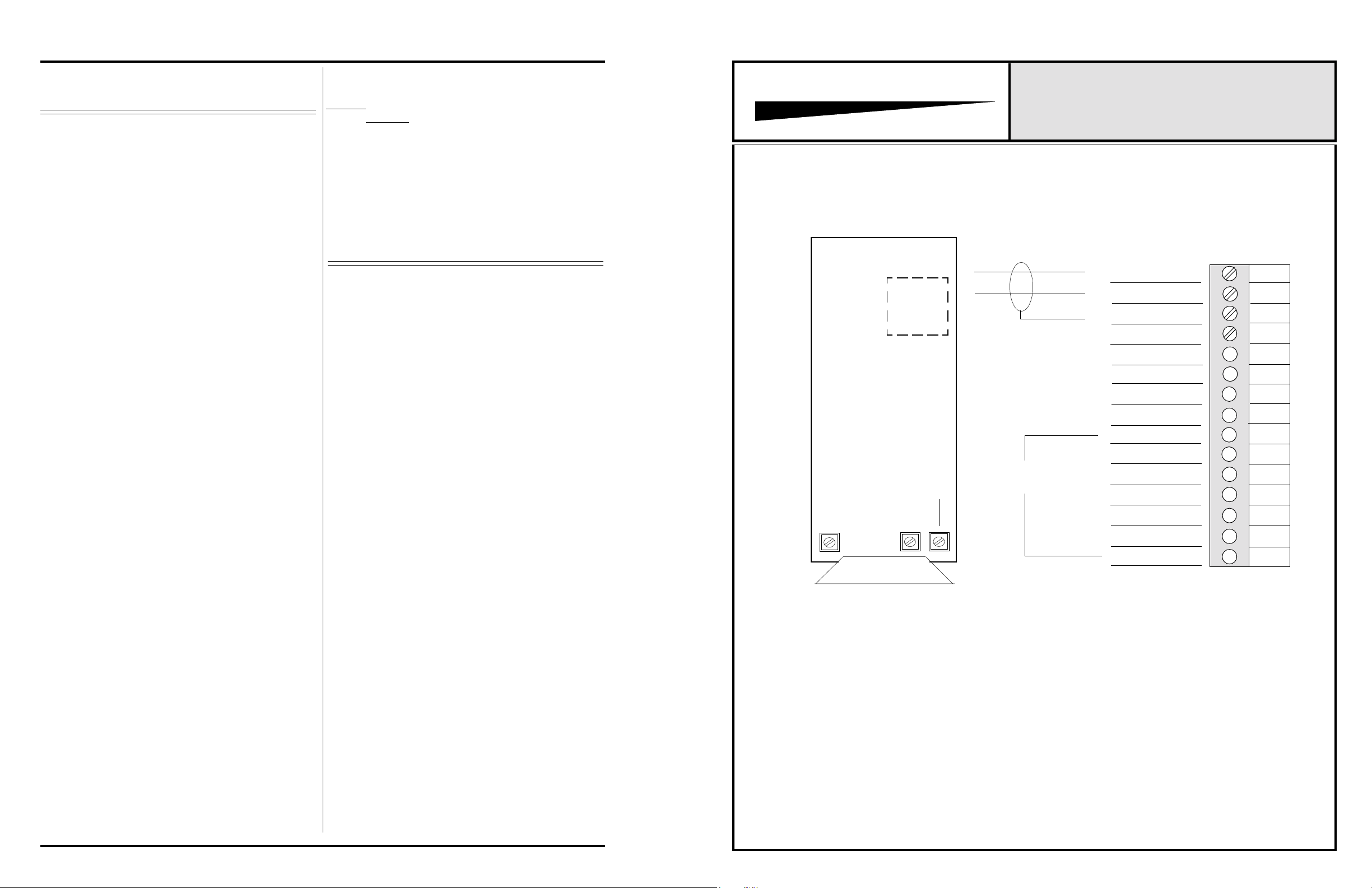
CONNECTOR & TRIMPOT DRAWING
MODEL 685
Both card frame assemblies bus the DC power to the individual
card slots, and provide screw-type barrier termination points
for audio and DC connections.
The determination as to which backplane assembly to use
in your project, was made prior to our factory receiving
the order. The backplane assembly you have received will
accommodate the group of cards you or your designer have
specified.
The actual steps necessary for installation of the Model 685
Tone Supervisor cards, are comparable to those necessary
for any of the INTEGRA III SYSTEM cards. They are as
follows;
1- Mount the card frame in an appropriate EIA 19" width
rack, using 4 screws of sufficient tensil strength
to provide secure mounting.
2- A determination has been made as to which type of power
supply will be used on your system. Follow the instructions
for the type of power supply you will be installing.
EXTERNAL POWER SUPPLY. If an external power
supply is to be used, terminate the proper supply
connections to pins 1, 2, & 3 of the DC barrier connector,
as shown in the card frame layout drawing,. Turn on the
power supply, and using a DC voltmeter, check for correct
voltage and polarity at pins 1,2, & 3 of the barrier connector.
INTERNAL POWER SUPPLY. If a plug-in power supply
card is to be used, plug in the supply card, and check for
proper illumination of both the positive and negative
voltage LED's, on the power supply card .
3 - Terminate all audio input and output connections, using
the card connection drawing on the facing page. Double
conductor shielded cable is recommended for all audio
connections.
ALIGNMENT
There are three trimpots on the Model 685 (see drawing on
facing page). O n e i s used to adjust the detector circuit for center
frequency of 25Hz. The second is used as an input level
adjustment. The third adjusts the relay dropout delay. The
frequency center alignment trimpot is factory adjusted for
25Hz, and should not require field adjustment. The
level adjustment trimpot is factory adjusted for minimum level
detection, and may not need adjustment, depending upon the
system designers specifications. The delay trimpot is factory
adjusted for maximum delay. If adjustments are necessary, the
following prodedure is recommended.
1- Apply the 25Hz tone, at a level which is representative of
the actual circuit being used, to the input pins of the tone
supervisor card. Monitor the card relay contacts with a
VOM, or at the annunciator panel, to see if the relay is
activated. If the relay has not activated, check input signal
frequency with a frequency counting meter to insure that the
proper frequency is being applied. If the frequency is correct, slowly turn the frequency centering trimpot until the
on-board LED turns on. The relay will now be activated.
2 - To adjust the input level trimpot, first make sure that the
detector circuit is activated. Slowly turn the level adjusting
trimpot until the on-board LED goes off. Then turn the trimpot
slowly the other way, until the LED is fully illuminated. This
adjusts the threshold of detection. If the input level should
drop more than 3dB, the detector circuit will deactivate.
3 - Adjust relay dropout delay trimpot until the desired delay is
achieved. (Note- timing ciruit triggers when LED goes off.
Make sure relay is deactivated, then increase input level until
LED goes on. Then lower input level until LED goes off, and
start timing delay adjustment.)
This completes the installation and alignment of your Model
685 Tone Supervisor Cards. The units may be expected to
deliver years of uninterrupted service.
Note #1- The alignment procedures for INTEGRA III SYSTEM Cards, differ from card type to card type. Therefore it is
necessary to consult the alignment procedure for each type of
card being installed, to properly align a card frame using
different card types.
K1
TYPICAL OF 600 OHM
OR 70 VOLT INPUT.
USE ONE ONLY.
RELAY
THRESHOLD
FREQUENCY
CENTER
CARD HANDLE
THRESHOLD TRIMPOT, CCW = LOWER THRESHOLD
DELAY TRIMPOT, CW = LONGER DELAY
DELAY
CONNECTIONS
857B & 858B BACKPLANE CONNECTIONS
INPUT LO 600/10K
INPUT HI 600/10K
GROUND
GROUND
INPUT HI 25/70 VOLT
INPUT LO 25/70 VOLT
GROUND
ARM B
ARM A
N/C A
N/O A
GROUND
N/C B
N/O B
1
2
3
4
5
6
7
8
9
10
11
12
13
14
15
Page 2
 Loading...