

Page 1
PROTECH
1/04
®
AUTOMATIC LEVEL CONTROL/LIMITER
INSTALLATION & OPERATION MANUAL
www.protechaudio.com
MODEL 65306
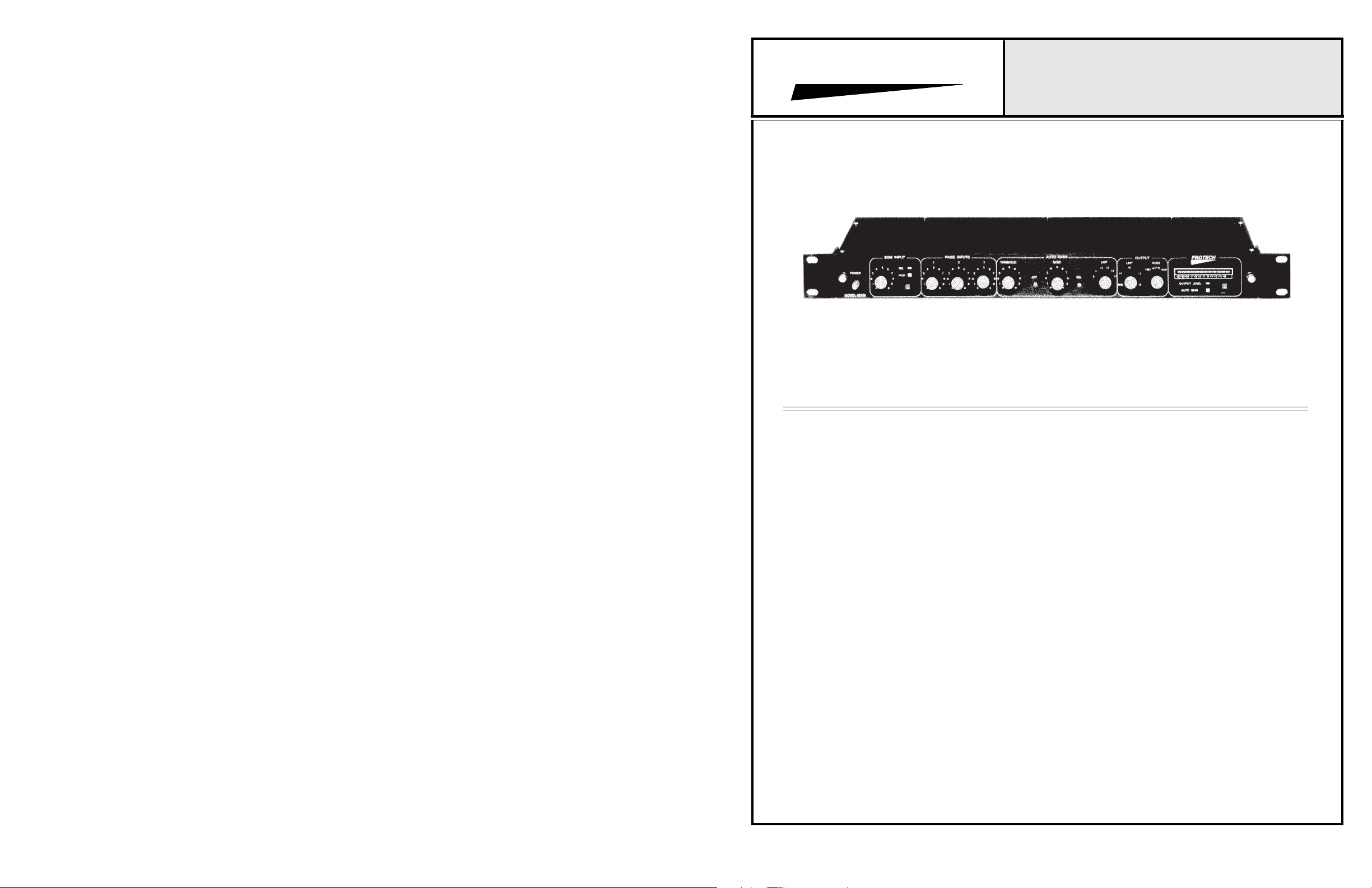
AMBIENT NOISE SENSING -
The Model 65306 Ambient Noise Sensing-Automatic
Level Control/Limiter is designed for use in professional sound installations. The unit listens to the
ambient noise level in a particular area, and raises and
lowers the paging and background music levels, in
accordance with changes in the ambient noise level.
The Model 65306 has a number of user definable
features, that allow the system designer to tailor the
performance to a particular installation.
The unit is designed to be placed in the program chain
prior to the power amplifiers, and after the paging and
background music sources. A sensing microphone, or
a sensing speaker, or even the paging speaker(s) may
be used as an ambient noise sensing device. (The
paging speakers may be used for sensing only when
there is no background music.) The sensing device
sends information on the present ambient noise condition, back to the Model 65306. Based on the
information the unit receives from the sensing
device, the 65306 raises or lowers the output level it
sends to the power amplifier(s).
The 65306 has three separate inputs for paging
sources, and one for the background music signal.
Applying an audio signal to any paging channel will
automatically mute the background music signal. In
addition, applying an audio signal to any higher level
paging channel will mute any lower level audio signal.
The 65306 may be used in either a freeze sensing
mode, or a continuous sensing mode. The freeze
sensing mode freezes the sensing level at the beginning of a page, and allows sensing to resume at the
end of a page. The continuous sensing mode allows
the unit to continue sensing thoughout the paging
announcements. The determination of which mode to
use is controlled by the wiring of the sensing device on
the rear barrier terminal.
The 65306 incorporates a relay which is automatically
activated when an audio signal is applied to any
program input. By wiring the sensing device thru the
relay terminals, the sensing device may be disconnected during paging. Continuous sensing may be
achieved, without fear of runaway gain, by simply
adjusting the Auto-Gain ratio pot The amount of AutoGain is controlled by the Gain Limit pot. This adjustment can be increased in 3dB increments, from 6dB to
21dB.
The output section incorporates a limiter, which can be
adjusted to control maximum output level.
In order to facilitate set-up, a MIN/AUTO/MAX switch
is incorporated into the 65306. The MIN position
allows quick alignment of the input section, the MAX
position allows a fast determination of how much Auto
Gain should be allowed. and the AUTO position allows
the unit to operate without operator intervention.
Protech Audio Corp., 192 Cedar River Road, Indian Lake, New York, 12842 Phone 518-648-6410 Fax 518-648-6395
Page 2
INSTALLATION
The Model 65306 is designed to be mounted in a
standard 19" width EIA rack. The position of the unit
in the rack is not critical, since it does not use
significant power, and therefore does not produce
heat.
After installing the Model 65306 in the audio rack,
wire all audio inputs and output using double conductor shielded cable. Various operating methods
may be used. In order to select the proper termination points for a particular operating method, refer to
the wiring diagrams on pages 3 - 5. If the speaker
grid is to be used as the sening device, care must be
taken to insure the wire gauge used is large enough
to handle the output power of the power amplifier.
Speakers may be used for sensing only when there is
no background music. Also, the internal speaker
switching relay in the Model 65306 is rated up to 100
watts. If power amplifiers rated over 100 watts are to
be used, an external switching relay is required (see
page 5).
INITIAL CONTROL POSITIONS
BGM Knob = Full CCW Position
BGM PRE/POST Switch = PRE Position
PGM #1 Knob = Full CCW Position
PGM #2 Knob = Full CCW Position
PGM #3 Knob = Full CCW Position
THRESHOLD Knob = Full CW Position
RATIO Knob = Full CW Position
GAIN LIMIT Knob = 6dB Position
LIMIT Knob = Full CW Position
MIN/AUTO/MAX Knob = MIN Position
ALIGNMENT
With MIN/AUTO/MAX switch in MIN position, apply
audio signals to each input, and adjust input control knob for
nominal -10dB output.
Turn MIN/AUTO/MAX switch to MAX position. Apply
audio signals to each input, and adjust AUTO GAIN
LIMIT switch set maximum gain to be allowed (for high
ambient noise condition).
Turn MIN/AUTO/MAX switch to AUTO position.
Set meter mode switch to AUTO GAIN.
Slowly, turn THRESHOLD control knob counterclockise
until meter indicates additional gain is being added to
output signal. Then, slowly turn THRESHOLD control
knob clockwise until additional gain is removed from
output signal. This will set the threshold of expansion
for the current ambient noise condition. It may be
necessary to repeat this adjustment several times, to fine
tune the adjustment. If the ambient noise level increases,
the Model 65306 will increase the output level.
IF NECESSARY ADJUSTMENTS-
If AUTO GAIN should add gain at a faster rate than
necessary, turn RATIO Knob CCW, until proper
rate is achieved.
IF necessary, adjust OUTPUT LIMIT knob CCW to
limit the overall output level. Remember, this level
must be higher than the combined initial output
level and the AUTO GAIN switch setting. i.e.-,
minus 10dB plus 12dB AUTO GAIN = +2dB.)
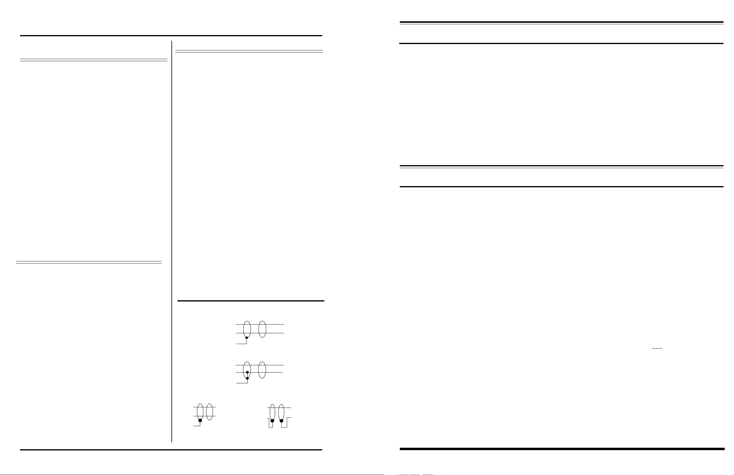
BALANCED INPUT CONNECTIONS
HI
LO
SH
UNBALANCED INPUT CONNECTIONS
HI
LO
SH
WHEN USING SPEAKERS FOR SENSING -
When using speakers for sensing, there are a few key items to consider.
First, sensing with speakers when background music is present, is not recommended. Although it has been
tried by some manufacturers, sensing with speakers when background music is present, does not work very
well. In order for the speaker to properly create the back EMF (electro-motor force) needed to send a signal to
the sensing input, the speaker should be de-energized for a period of 1 to 2 seconds. This is to allow the speaker to reach a zero output condition. Next, the speaker should be allowed to react to the ambient noise condition
for a period of 2-3 seconds. This allows the speaker to create an average output level, instead of reacting to a
cough or a yell.
There are only two ways to create these 3-5 second pauses in the background music. One is to have the ambient level controller interupt the music every 15 to 20 seconds. This creates a very noticeable, and unpleasant
effect on the background music. The second is to purchase prerecorded music with the pauses built-in every12 minutes. This condition does not allow the level controller to react properly to all changes in ambient noise
condition.
A WORD ON ADJUSTING THRESHOLD AND RATIO CONTROLS -
The threshold control determines when the Model 65306 starts to add additional gain, in relation to the
ambient noise level. The control has been optimized for operation at 11:00. The majority of installations will work well
at this adjustment level. However there are installations that may require a small adjustment form this 11:00 position.
By turning the threshold control counterclockwise, the unit will react to lower ambient noise levels. This can be seen
by setting the meter mode switch in the "AUTO GAIN" position, and the output mode switch to the "AUTO" position.
When the threshold control is turned fully clockwise, no LED's will be illuminated. By turning the threshold control to
the full counterclockwise position, some or all LED's will light up, depending on the type of sensing device that is
attached to the sensing input, and the auto gain "LIMIT" switch position. This indicates the amount of additional gain
the unit is adding to the initial signal level. During a quiet ambient noise period, the threshold control should be adjusted so that the lowest level LED just turns off. Remember, this is an average responding circuit, and will take 5-30
seconds to settle to the most recent adjustment.
The ratio control determines how fast the Model 65306 adds gain, in relation to changes in the ambient noise
level. In some installations, a slower than 1:1 ratio may be desired. Also, if the speaker system should create
additional reverberations in the area of the sensing device, a slower ratio may be wanted. By slowing down
the ratio (counterclockwise), the sensing device may receive reverberations from the near-field speakers, but
would still require additional input noise before it could raise the out level any significant amount. For
instance, if the ratio is set to 2:1, the unit would require 2dB of speaker reverberations and 2 dB of ambient
noise level change, befor it could raise the output level 2dB.
METER SWITCH = Output Position
BALANCED & UNBALANCED OUTPUT CONNECTIONS
Page 2
HI
LO
SH
BALANCED
TO POWER
AMPLIFIER
HI
LO
UNBALANCED
TO POWER
AMPLIFIER
8/95
- Page 7 -
Page 3
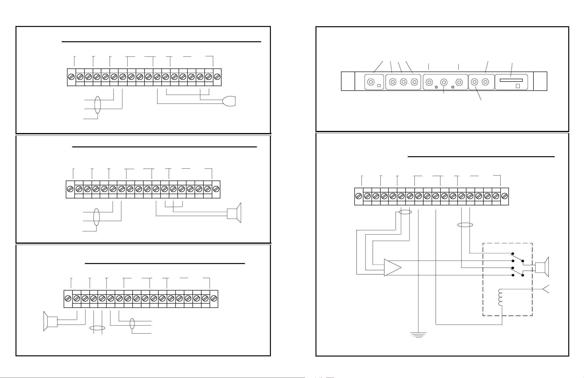
SENSING INPUT CONNECTIONS
USING A MICROPHONE FOR PAUSE DURING PAGE NOISE SENSING.
CONTROLS
TO
POWER AMP
INPUT
USING A SPEAKER FOR PAUSE DURING PAGE NOISE SENSING.
SPKR GRID
PWR AMP
OUTPUT
PWR AMP
INPUT
RELAY PAUSE
N/O N/C
SPKR GRID RELAY PAUSE
PWR AMP
OUTPUT
PWR AMP
INPUT
N/O N/C
RATIO
CONTROLS
HOW MUCH
GAIN IS
ADDED
GAIN LIMIT
REL
LIMIT
SET-UP
SWITCH
AUTO
MIN
MAX
METER
SECTION
AUTO GAIN
OUTPUT
CONTROLS
PAGE 3
WHEN
AUTO GAIN
STARTS
THRESHOLD
ATT
SENSE
SPKR
HIGNDARMHILOLO LO HIHI
SENSING
MIC
HILO
SH
HILO
BGM
INPUT LEVEL
ADJUSTMENTS
PAGE 1
PRE
POST
PAGE 2
CONTROLS
HOW FAST
AUTO GAIN
INCREASES
CONTROLS
TOTAL
OUTPUT
LEVEL
USING PAGING SPEAKER GRID FOR NOISE SENSING
WITH POWER AMPLIFIERS OVER 100 WATTS.
SENSE
SPKR
HIGNDARMHILOLO LO HIHI
SENSING
MIC
HILO
SH
HILO
SPKR GRID
PWR AMP
OUTPUT
PWR AMP
INPUT
RELAY PAUSE
N/O N/C
ARMHILOLO LO HIHI
GND
SENSE
SPKR
HI
LO
SENSING
MIC
HI
HILOSH
TO
POWER AMP
INPUT
SPKR GRID
USING PAGING SPEAKER GRID FOR NOISE SENSING,
UP TO 100 WATT AMPLIFIERS.
PWR AMP
OUTPUT
TO POWER AMP
OUTPUT
PWR AMP
INPUT
RELAY
N/O N/C
PAUSE
GND
ARMHILOLO LO HIHI
SENSE
SPKR
HI
LO
SENSING
MIC
HI
HILOSH
TO
POWER AMP
INPUT
EXTERNAL RELAY
5-10 AMP CONTACT
RATING
POWER AMP
INPUT
POWER AMP
OUTPUT
+24VDC
EXTERNAL
POWER
SUPPLY
GROUND
FROM
EXTERNAL
POWER
SUPPLY
Page 4
Page 5
Page 4

1 TO THREE PAGE INPUTS CAN BE USED, PLUS BGM
FOR EXTERNAL
SWITCHING
INPUT ONE
NORMALED
THRU RELAY FOR
AMP
POWER
POWER OFF
BYPASS
OUTPUT BUFFER
WITH SELECTABLE
MAXIMUM OUTPUT
(LIMITER)
LED METERING OF
OUTPUT LEVEL, OR,
EXPANSION LEVEL
MODEL 65306 BLOCK DIAGRAM
FILE #65306-06, REV 2, 12-7-95
PAGE 3 IN
PAGE INPUT 3
IS NORMALLED
THRU BYPASS
RELAY WHEN
POWER IS OFF
PAGE 2 IN
PAGE 1 IN
HILOHILOSHHILO
BGM IN
HILOSH
USING A MICROPHONE FOR CONTINUOUS NOISE SENSING.
INPUTS
SPKR GRID
PWR AMP
OUTPUT
PWR AMP
INPUT
RELAY
N/O N/C
PAUSE
SENSE
SPKR
SENSING
MIC
HIGNDARMHILOLO LO HIHI
HILOSHHILO
CONTROL CIRCUIT FOR
VCA, INCLUDING -
THRESHOLD
ATTACK TIME
RELEASE TIME
RATIO OF EXPANSION
EXPANDER LIMIT
VOX
CIRCUIT FOR
RELAY DRIVE
SWITCH
MIN/AUTO/MAX
PRIOR.
3
SUM
VCA
SUM
PRIOR.
2
4:1 COMPRES-
SOR
FIXED -20dB
THRESHOLD
PRIOR.
1
BGM
PRIOR.
PROTECH AUDIO CORPORATION
USING A SPEAKER FOR CONTINUOUS NOISE SENSING.
TO
POWER AMP
INPUT
TO
POWER AMP
INPUT
SPKR GRID
PWR AMP
OUTPUT
PWR AMP
INPUT
RELAY PAUSE
N/O N/C
SENSE
SPKR
HIGNDARMHILOLO LO HIHI
SENSING
MIC
HILOSHHILO
PAUSE
SENSE
CONTACTS
SENSE INPUT
SPEAKER
SENSE INPUT
MICROPHONE
- Page 6 -
Page 3
 Loading...