

Page 1
PROTECH
®
1/02
PROGRAMMABLE
SOLID-STATE SWITCHING CARD
INSTALLATION & OPERATION MANUAL
MODELS COVERED
INTEGRA III SYSTEM
590B
www.protechaudio.com
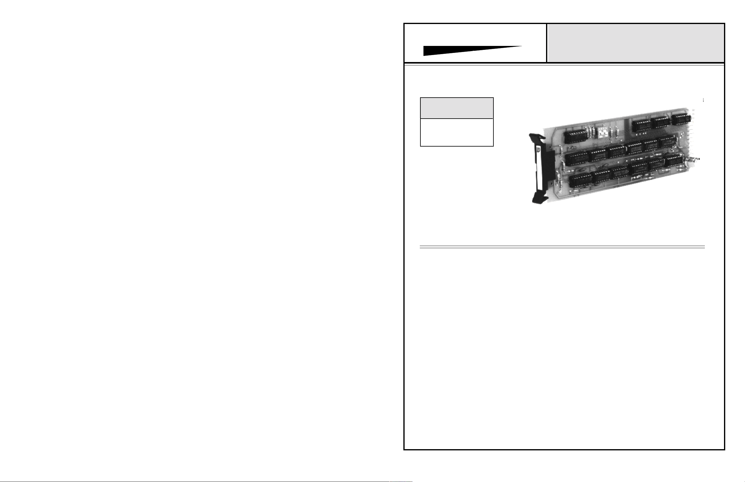
The 590B Programmable solid-state switching card is
designed for use in professional audio applications. The
card is constructed to function as a solid-state switch.
There are five pairs of Form A contacts on each switch
card. The switch contacts are activated by a remote
closure to ground.
Typical applications are public address systems,
broadcast studios, sales presentation rooms, headphone
listening systems, multi-room audio systems, and recording systems. The actual application of the amplifiers is
found in buildings such as airports,
factories, courthouses, casinos, convention centers,
libraries, hotels, racetracks, training systems, corporate
boardrooms, etc.,.
The 590B has four logic programs built-in to each card.
The programs are selectable via an on-board dip switch.
The first program is designated "Independent". This program allows each set of contacts to operate independently
of each other.
The second program is designated "Lockout". This program operates on the first-come, first-served principle,
with all other closures locked out until the active channel is
released. This program is very useful in paging applications.
Model 590 Shown
The third program is designated "Last-On". This program
allows the active channel to be turned off whenever a new
channel closure is selected. This program is extremely
useful in legislative venues, where the chairman wishes
to assign access to the public address system.
The fourth program is designated "All-On". When the card
is set for this program any ground closure will activate all
five sets of closures. This program is useful in controlling
multiple outputs from devices such as audio distribution
amplifiers.
The Model 590B card is linkable. Multiple cards may be
linked together to create 10, 15, 20, etc. channel electronic
switches. Four cards linked together, with switches set for
the "Lockout" program, create a 20 station electronic
switch with first-come, first-served capability.
Multiple cards, set to different programs may be used
together to accomodate various systems requirements. Other
INTEGRA III SYSTEM switching cards may be used in
conjunction with the Model 590B to provide additional
switching functions.
Each of these products is designed to provide the user with
high quality audio, for years of uninterrupted service.
Protech Audio Corporation, PO Box 597, 192 Cedar River Road, Indian Lake, New York, 12842, Voice 518-648-6410 Fax 518-648-6395
Page 2
INSTALLATION
The 590B Programmable Switching Card is designed to be
mounted in the Model 857B Card Frame or the Model 858B
Card Frame.
The Model 857B Card Frame will accomodate up to 10 audio
cards, and requires an external power supply (Model 66708).
The Model 858B Card Frame will accomodate up to 9 audio
cards, and has a built-in unpluggable power supply card.
Both card frame assemblies bus the DC power to the individual
card slots, and provide screw-type barrier termination points for
audio and DC connections.
The determination as to which backplane assembly to use in
your project, was made prior to our factory receiving the order.
The backplane assembly you have received will accommodate the group of cards you or your designer have specified.
The actual steps necessary for installation of the 590B Programmable switching card, are comparable to those necessary for
any of the INTEGRA III SYSTEM cards. They are as follows:
1- Mount the card frame in an appropriate EIA 19" width rack,
using 4 screws of sufficient tensile strength to provide secure
mounting.
4- Unpack each individual card, inspect for shipping
damage, and assuming none is found, slide the card
half-way into the appropriate slot. After all cards have been
installed half-way into the card frame, plug in one card at a time
and turn on the power supply. Make sure no unusual loading is
noticed at the power supply. If loading is no ticed, turn off the
power supply, unplug the card and recheck terminations. If no
loading is noticed, continue inserting each card in the card
frame, checking power supply loading as each card is plugged
in. When all the cards have been plugged in, the installation is
complete, and all that remains is the alignment.
ALIGNMENT
The Model 590B does not require alignment. The only adjustments to the card are the switch settings which determine
the logic program to be used (See facing page).
Operation of the unit may be checked in the following
manner.
1- Apply power to Model 590B.
2- Apply a signal representative of the actual signal level to
be used, to contacts 1A & 1B inputs.
3- While monitoring contacts 1A & 1B outputs, ground
switch #1 (Pin 10). Check for proper signal level at the
output pins.
4- Repeat steps 3 & 4 for each switch channel on the
Model 590B. If the card is to be used in any program other
than independent, make switch ground closures in
sequence to check that the logic program is operating as
desired. If it is not, recheck program switch settings.
PROTECH
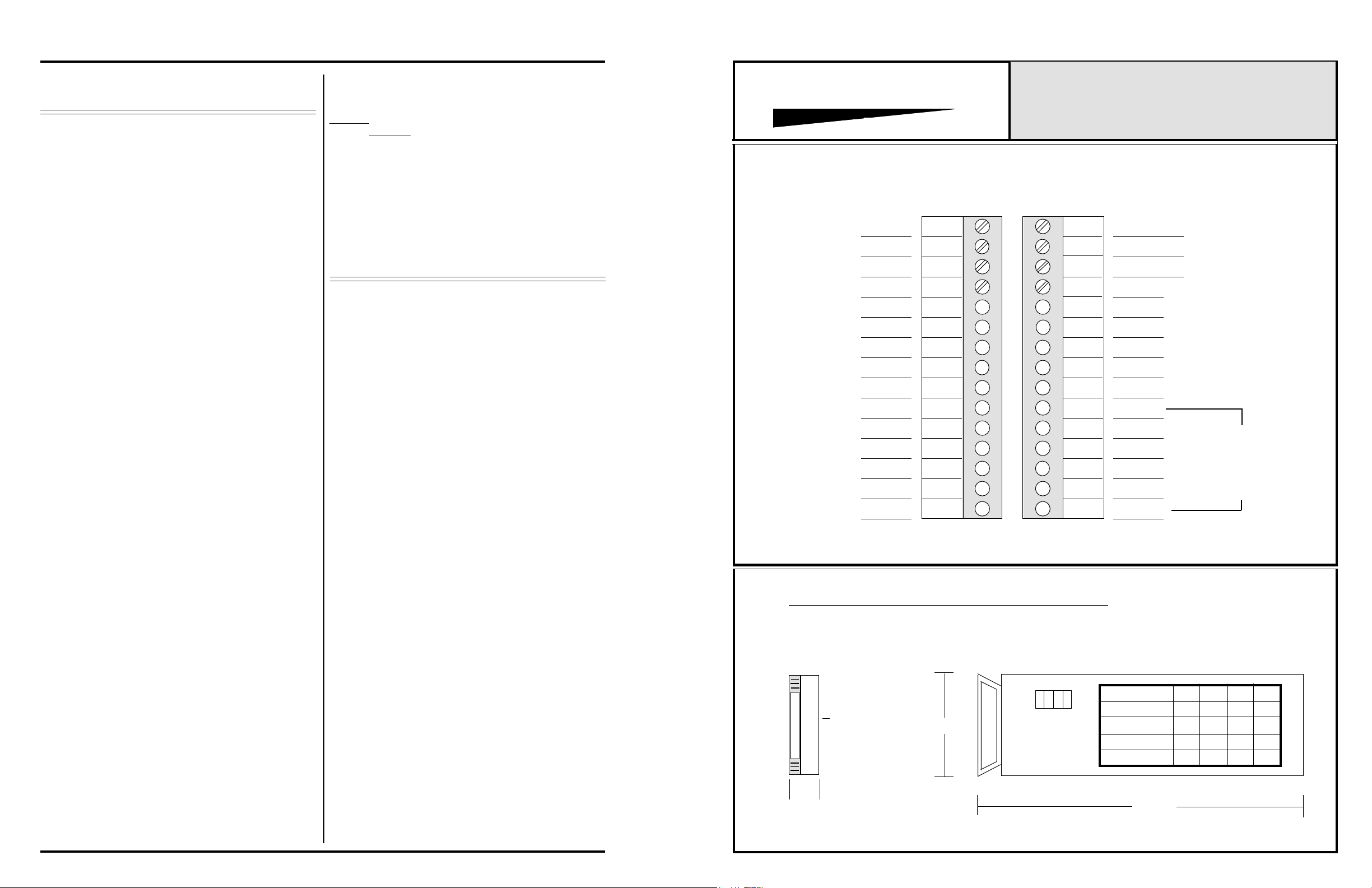
857B & 858B Backplane Connections.
4B, OUT
4A, IN
4A, OUT
3B, IN
3B, OUT
3A, IN
3A, OUT
2B, IN
2B, OUT
2A, IN
2A, OUT
1B, IN
1B, OUT
1A, IN
1A, OUT
16
17
18
19
20
21
22
23
24
25
26
27
28
29
30
®
INTEGRA III SYSTEM
CONNECTOR & PROGRAM DRAWING
MODEL 590B
1
2
3
4
5
6
7
8
9
10
11
5A, IN
5A, OUT
GROUND
4B, IN
5B, OUT
5B, IN
LINK-1
GROUND
LINK-2
SWITCH 1
SWITCH 2
APPLY POWER TO
12
13
14
15
SWITCH 3
GROUND
SWITCH 5
SWITCH 4
MODEL 590B
BEFORE MAKING
SWITCH CLOSURES
2- A determination has been made as to which type of power
supply will be used on your system. Follow the instructions for
the type of power supply you will be installing.
EXTERNAL POWER SUPPLY. If an external power supply
is to be used, terminate the proper supply connections
to pins 1, 2, & 3 of the DC connector, as shown in the card frame
layout drawing Turn on the power supply, and using a DC
voltmeter, check for correct voltage and polarity at pins 1, 2, &
3 of of the DC cpnnector.
INTERNAL POWER SUPPLY. If a plug-in power supply card
is to be used, plug in the supply card, and check for proper
illumination of both plus and minus DC green LED's.
3- Terminate all audio input and output connections, using the
card connection drawing on the facing page. Shielded cable is
recommended for all audio connections.
This completes the installation and alignment of your Model
590 Programmable Sswitching Card. The card(s) may be expected to deliver years of uninterrupted service.
Note 1The alignment procedures for INTEGRA III SYSTEM cards,
differ from card type to card type. Therefore it is necessary
to consult the alignment procedure for each type of card being
installed, to properly align a card frame using different card
types.
Page 2
PROGRAM SWITCH DRAWING, MODEL 590B
FRONT VIEW
4 3 2 1
SWITCH
0.75"
COMPONENT
SIDE
2.5"
SIDE VIEW
FUNCTION
INDEPENDENT OFF ON
LOCKOUT
ALL ON
LAST ON
8.0"
SW3
SW4
OFF OFF
ON ON
OFF
ON ON ON
SW1SW2
OFF
ON
ON
OFF
ON ON
 Loading...