

Page 1
PROTECH
MODELS COVERED
589
1/02
®
INTEGRA III SYSTEM
AUDIO CONTROLLED SWITCH
INSTALLATION & OPERATION MANUAL
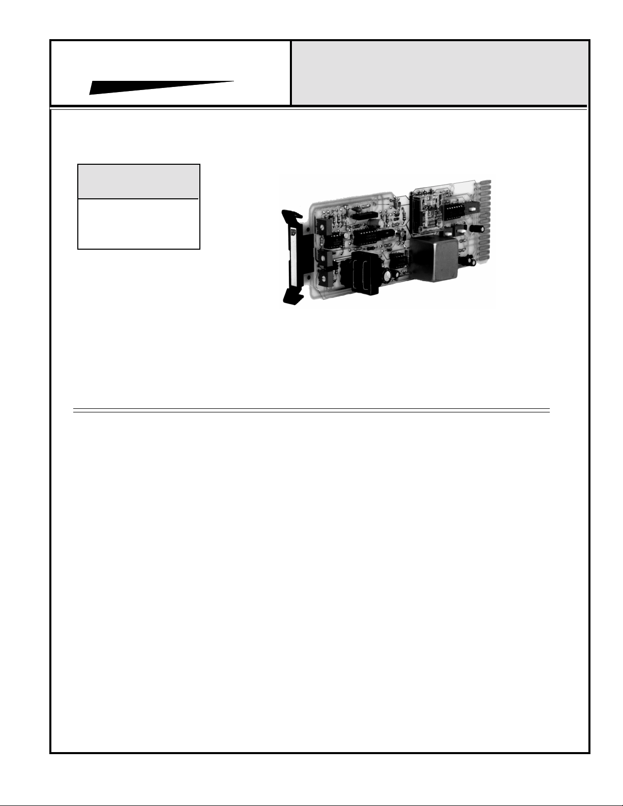
Model 589 Shown
www.protechaudio.com
The Protech Audio Model 589 is a high quality
audio controlled switch coupled with a professional quality preamplifier. The unit is designed
for applications requiring switch closures to
follow the presence of an audio signal.
Typical applications are public address
systems, broadcast studios, sales presentation
rooms, headphone listening systems, multiroom audio systems, and recording systems.
The actual application of the amplifiers is
found in buildings such as airports, factories,
courthouses, casinos, convention centers,
libraries, hotels, racetracks, training systems, corporate boardrooms, etc.,.
The unit is capable of functioning in a wide
variety of installations. A typical application
would be the turning on of bypass relays in
paging systems during priority announcement.
Multiple units may be used to design a multilevel priority system. The switch-selectable remote threshold capability allows this unit to
serve well in systems requiring different threshold levels at different times of the day.
The built-in preamplifier, is switch selectable to
serve as either a microphone preamplifier, or a
line amlifier.
The built-in preamplifier is a very cost effective
feature, eliminating the need for separate microphone or line level preamplifiers.
The Model 589 features two different types of
closures, CMOS and Relay. The relay closures are
configured in two Form C contact arrangements.
The CMOS closures are arranged in two Form A
contacts. The relay closures are capable of switching high current loads. The CMOS is recommended for lower level audio (microphone level)
switching, since they introduce no switching
noise. Both sets of contacts have an adjustable
threshold, to determine when they activate, as
well as an adjustable drop-out delay, to
determine how quickly the switch opens, after
the incoming audio stops.
The Model 589 is designed to mount in the Model
857B or 858B Card Frame. The unit may be mixed
or matched with other INTEGRA III SYSTEM cards
to create a complete audio system.
The Model 589 Audio Controlled Switch may be
expected to provide years of uninterrupted, quality
service. For additional information, or design assistance contact:
APPLICATIONS ASSISTANCE
Protech Audio Corporation, PO Box 597, 192 Cedar River Road, Indian Lake, New York, 12842, Voice 518-648-6410 Fax 518-648-6395
Page 2

INSTALLATION
INSTALLATION
The 589 Audio Controlled Switching Card is designed
to be mounted in the Model 857B Card Frame, or
the Model 858B Card Frame.
The Model 857B Card Frame will accomodate up to 10
audio cards, and requires an external power supply.
The Model 858B Card Frame will accomodate up to 9
audio cards, and has a built-in, unpluggable power supply
card.
Both card frame assemblies bus the DC power to the
individual card slots, and provide screw-type barrier termination points for audio and DC connections.
The determination as to which card frame assembly
to use in your project, was made prior to our factory
receiving the order. The card frame assembly you have
received will accommodate the group of cards you or
your designer have specified.
4- Unpack each individual card, inspect for shipping
damage, and assuming none is found, slide the card
half-way into the appropriate slot. After all cards have
been installed half-way into the card frame, plug in one
card at a time and turn on the power supply, unplug the
card and recheck terminations. If n o loading is noticed,
continue inserting each card in the card frame, checking
power supply loading as each card is plugged in. When all
the cards have been plugged in, the installation is
complete, and all the remains is the alignment.
ALIGNMENT
The model 589 has been shipped from the factory with;
1-Input selector switch (S1) in the line position.
2-Gain Aligned for Unity
3-Threshold selector switch (S2) in the On-Board position.
4-Threshold adjustment set for -20dB.
5-Contact selector switch (S3) in the relay position.
The actual steps necessary for installation of the Model
589, are comparable to those necessary for any of the
INTEGRA III SYSTEM cards. They are as follows:
1- Mount the card frame in an appropriate EIA 19" width
rack, using 4 screws of sufficient tensile strength to
provide secure mounting.
2- A determination has been made as to which type of
power supply will be used on your system. Follow the
instructions for the type of power supply you will be
installing.
EXTERNAL POWER SUPPLY.
If an external power supply is to be used, terminate
the proper supply connections to pins 1, 2, & 3 of the
DC barrier connector , as shown in the card frame layout
drawing. Turn on the power supply, and using a DC
voltmeter, check for correct voltage and polarity at pins
1, 2, & 3 of the barrier connector.
INTERNAL POWER SUPPLY.
If a plug-in power supply card is to be used, plug in
the supply card, and check for proper illumination of
both the positive and negative voltage LED's, on the
power supply card front panel.
3- Terminate all audio input and output connections,
using the card connection drawing on the facing page.
Double conductor shielded cable is recommended for
all audio connections. Terminate each unused input with
a 1K ohm resistor.
If additional gain is required, the following alignment procedure is recommended;
1- Remove the card from the card frame, and realign
switches to desired positions.
2- Replace card in slot.
3- Apply a signal representative of the actual signal to be
used, to the input.
4- While monitoring the output, turn the gain trimpot clock wise until the desired output level is reached.
5- Adjust threshold trimpot as required. The green LED
indicates the threshold/switch action.
6- Adjust dropout delay as necessary.
This completes the installation and alignment of the audio
controlled switching card. The cards may be expected to
deliver years of uninterrupted service.
Note 1The alignment procedures for INTEGRA III SYSTEM cards
differ, from card type to card type. Therefore, it is necessary
to consult the alignment procedure for each type of card
being installed.
Page 2
Page 3

PROTECH AUDIO
®
CONNECTOR & TRIMPOT DRAWING
MODEL 589 AUDIO CONTROLLED SWITCH CARD
MODELS 857B & 858B BACKPLANE CONNECTIONS
INTEGRA III SYSTEM
S3
Relay
Cmos
K1
S1
S2
Mic In
Line In
Remote Pot
On-Board Pot
T1
T2
K1 N/O B/CMOS OUT B
K1 ARM A
GROUND
K1 N/O A/CMOS OUT A
K1 N/C B/CMOS IN B
K1 N/C A/CMOS IN A
(REMOTE POT HI)
(REMOTE POT LO)
(REMOTE POT ARM)
INPUT HI
INPUT LO
K1 ARM B
GROUND
OUTPUT HI
OUTPUT LO
1
2
3
4
5
6
7
8
9
10
11
12
13
14
15
Delay
Threshold
Gain
CW = Longer delay
CW = Higher Threshold
CW = More gain
Page 3
 Loading...