

Page 1
PROTECH
MODELS COVERED
586
®
1/06
INTEGRA III SYSTEM
INSTALLATION & OPERATION
MANUAL
NOISE GENERATOR CARD
www.protechaudio.com
The Model 586 Noise Generator card is designed pink
or white noise for use in masking or alignment of audio
systems.
Typical applications are public address systems, sound
reinforcement systems, and room combining systems.
The actual application of the noise generator card is
found in such buildings as airports, factories, courthouses, casinos, convention centers, hotels, racetracks, training systems, corporate boardrooms, and
office buildings.
The model 586 consists of two separate circuits. The
first section is a digital noise generator. The output of
the noise generator circuit is standard white noise.
The white noise is fed to a push-on jumper area of the
card, and to a filter, the output of which is standard
pink noise. The pink noise is also fed to the push-on
jumper area. By placing the push-on jumper on the
desired pins, the user may select either white or pink
noise. The card is shipped from the factory strapped
for pink noise. To select white noise, simply move the
red push-on jumper to the other set of pins. The
jumpers are located in the middle of the PC board
assembly, next to the output section.
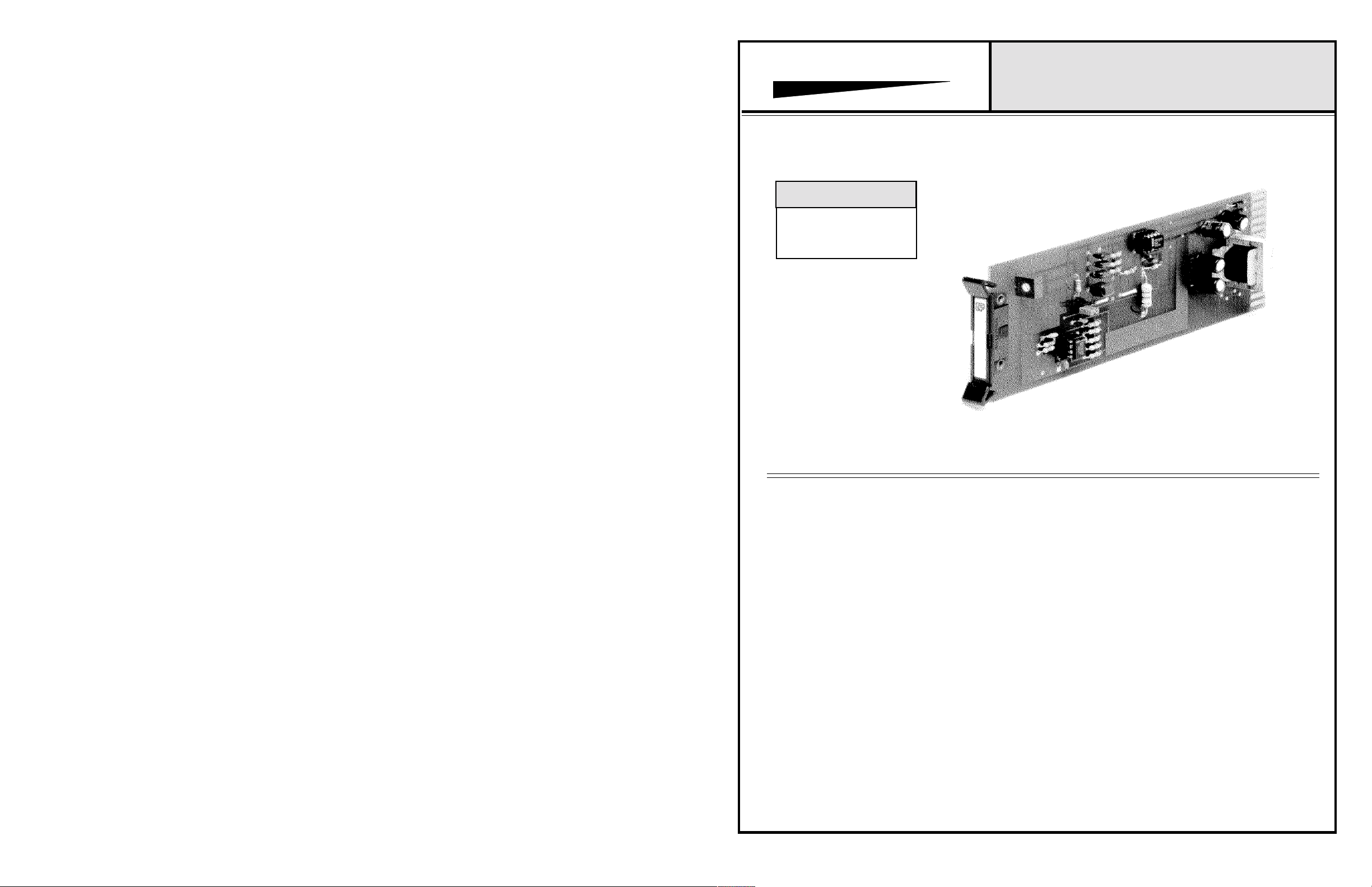
Model 586 Shown
The second circuit consists of a balanced line output,
with adjustable gain. The gain is adjusted via the trimpot
mounted on the front of the PC board assembly. The
maximum output level for the pink noise is -5dB into 600
ohms. The maximum output of the white noise is +15dB
into 600 ohms. The output section of the card is transformer isolated, and should be terminated into a 600-10K
ohm load.
The Model 586 may be mixed or matched with other
INTEGRA III SYSTEM components, within the same
card frame, without degradation in performance. For
larger installations, the output of the Model 586 may be
fed into the audio distribution amplifier cards, to serve
more areas. As one of the INTEGRA III SYSTEM audio
cards, the Model 586 may be mounted in any of the
system enclosures manufactured by Protech Audio Corp.
The Model 586 Noise Generator Card may be expected to
provide the user with years of dependable, uninterrupted quality service. For additional information, or
design assistance, contact:
APPLICATIONS ASSISTANCE
Protech Audio Corporation, PO Box 597, 192 Cedar River Road, Indian Lake, New York, 12842, Voice 518-648-6410 Fax 518-648-6395
Page 2
INSTALLATION
The 586 Noise Generator Card is designed to be mounted
in the Model 857B Card Frame , or the Model 858B Card
Frame.
The Model 857B Card Frame will accomodate up to 10 audio
cards, and requires an external power supply (Model 66708).
The Model 858B Card Frame Package will accomodate up to
9 audio cards, and has a built-in, unpluggable power supply
card.
Both card frame assemblies bus the DC power to the individual
card slots, and provide screw-type barrier termination points
for audio and DC connections.
The determination as to which card frame assembly to use
in your project, was made prior to our factory receiving the order.
The card frame assembly you have received will
accommodate the group of cards you or your designer have
specified.
The actual steps necessary for installation of the Model 586
Noise Generator cards, are comparable to those necessary for
any of the INTEGRA III SYSTEM cards. They are as follows:
1- Mount the card frame in an appropriate EIA 19" width rack,
using 4 screws of sufficient tensile strength to provide secure
mounting.
2- A determination has been made as to which type of power
supply will be used on your system. Follow the instructions for
the type of power supply you will be installing.
EXTERNAL POWER SUPPLY.
If an external power supply is to be used, terminate the proper
supply connections to pins 1, 2, & 3 of the DC barrier connector
, as shown in the card frame layout drawing. Turn on the
power supply, and using a DC voltmeter, check for correct
voltage and polarity at pins 1, 2, & 3 of the barrier connector.
4- Unpack each individual card, inspect for shipping
damage, and assuming none is found, slide the card
half-way into the appropriate slot. After all cards have been
installed
and turn on the power supply. Make sure no unusual loading is
noticed at the power supply. If loading is noticed, turn off the
power supply, unplug the card and recheck terminations. If no
loading is noticed, continue inserting each card in the card frame,
checking power supply loading as each card is plugged in. When
all the cards have been plugged in, the installation is complete,
and all that remains is the alignment.
half-way into the card frame, plug in one card at a time
ALIGNMENT
The Model 586 has been shipped from the factory strapped for
pink noise output and -20dB into 600 ohms output level.
If additional gain or white noise output is required, the
following alignment procedure is recommended;
1 - Remove card from frame, move push-on jumper to white
noise position, and turn trimpot completely counterclock
wise. Replace card in frame
2 - While monitoring the output channel, turn the output
gain trimpot clockwise until the desired output level is
reached.
This completes the installation and alignment of your noise
generator cards. The cards may be expected to deliver years of
uninterrupted service.
PROTECH AUDIO
T1
DIGITAL
NOISE
GENERATOR
WHITE NOISE
JUMPER
PINK NOISE
JUMPER
GAIN
CARD HANDLE
®
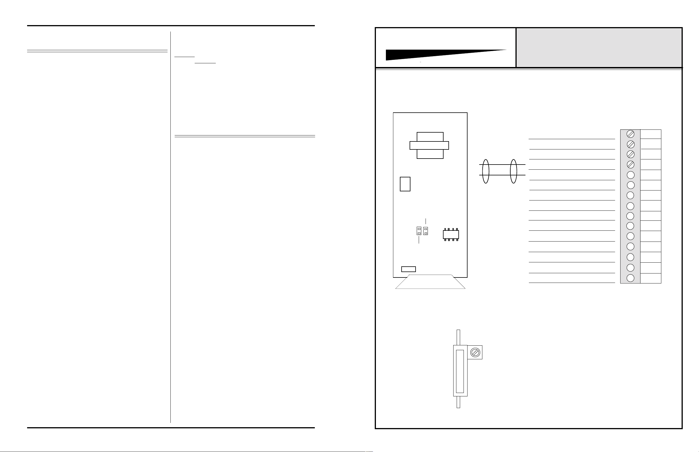
CONNECTOR & TRIMPOT DRAWING
857B & 858B BACKPLANE CONNECTIONS
INTEGRA III SYSTEM
MODEL 586
1
2
GND
OUTPUT HI
OUTPUT LO
3
4
5
6
7
GND
8
9
10
11
12
GND
13
14
15
INTERNAL POWER SUPPLY.
If a plug-in power supply card is to be used, plug in the
supply card, and check for proper illumination of both the
positive and negative voltage LED's, on the power supply
card.
3- Terminate all audio input and output connections, using
the card connection drawing on the facing page. Double
conductor shielded cable is recommended for all audio
connections. Terminate each unused input with a 1K ohm
resistor.
Note 1 The alignment procedures for INTEGRA III SYSTEM cards,
differ from card type to card type. Therefore it is necessary to
consult the alignment procedure for each type of card being
installed, to properly align a card frame using different card
types.
Page 2
GAIN
Page 3
 Loading...