

Page 1
PROTECH
MODELS COVERED
571B
®
1/02
RELAY SWITCHING CARD
INSTALLATION & OPERATION MANUAL
INTEGRA III SYSTEM
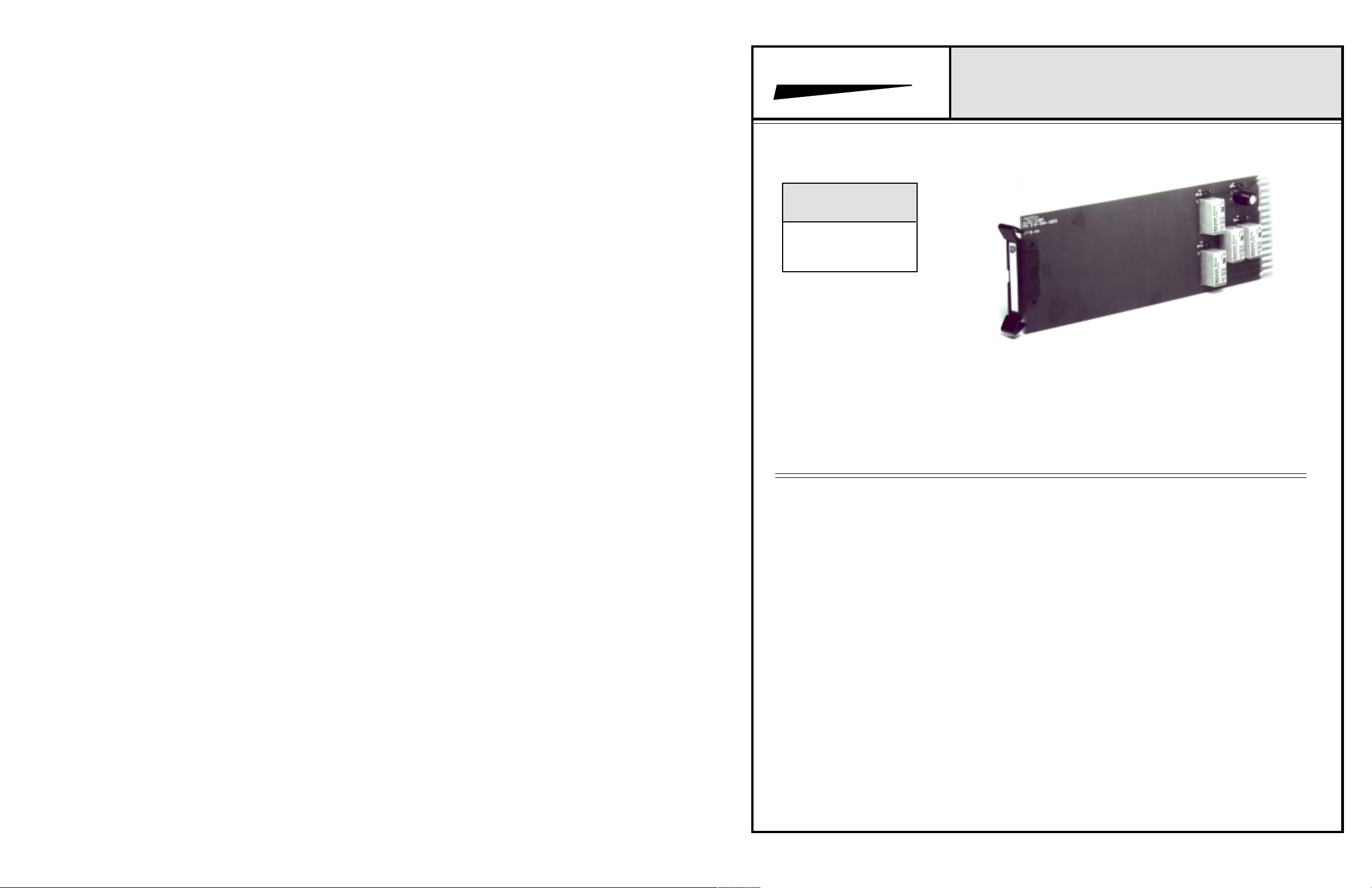
Model 571B Shown
www.protechaudio.com
T h e M odel 571B Relay Switcher Card is designed
to operate as a remote switching control in
professional audio systems.
Typical applications a r e p ublic address systems,
broadcast studios, sales presentation rooms, headphone listening systems, multi-room audio systems,
and recording systems. The actual application of the
amplifiers is found in buildings such as airports,
factories, courthouses, casinos, convention centers,
libraries, hotels, racetracks, training systems, corporate boardrooms, etc.
The Model 571B incorporates 2 separate, double
pole-double throw relay circuits, and, a 4 pole-double
throw relay circuit.. The relays are mounted on a
single, plug-in printed circuit board. Each relay has
Form C contact arrangement. The relays are activated by grounding the control pin. Relay control pins
may be ganged together to operate more than one
relay from a single switch closure. Different combinations of relays may be created by isolating the remote
switch closures through diodes.
The form C contacts allow switching between two
independent audio sources, or, sending an audio
signal to either of two separate destinations. By
ganging several relay card in series, it is possible to
create a larger audio switching matrix. The relay cards
are designed to operate alone or in conjunction with
other switching cards in the INTEGRA III SYSTEM.
The Model 571B is designed to mount in the Models
857B or 858B Card Frames. The unit may be mixed
or matched with other INTEGRA III SYSTEM cards to
create a complete audio system.
The card frames will allow mounting of either 9 audio
cards and plug-in power supply card (Model 858B), or
10 audio or switching cards when used with an
external power supply (Model 857B). If additional
information is needed, contact Applications Assistance by calling 631-584-5855.
The relay cards may be expected to provide years of
uninterrupted, quality service.
Protech Audio Corporation, PO Box 597, 192 Cedar River Road, Indian Lake, New York, 12842, Voice 518-648-6410 Fax 518-648-6395
Page 2
INSTALLATION
The 571B Relay Switching Card is designed to be
mounted in the Model 857B, or 858B Card Frame
Assembly.
The Model 857B Card Frame will accomodate up to 10
audio cards, and requires an external power supply (Model
66708).
The Model 858B Card Frame will accomodate up to
9 audio cards, and has a built-in power supply card
(Models 2000-PS-A).
Both card frames assemblies bus the DC power to the
individual card slots, and provide screw-type barrier termination points for audio and DC connections.
The determination as to which backplane assembly to use
in your project, was made prior to our factory receiving the
order. The backplane assembly you have received will
accomodate the group of cards you or your designer have
speciifed.
The actual steps necessary for installation of the 571B
Relay card, are comparable to those necessary for any
of the INTEGRA III SYSTEM cards. They are as follows:
1- Mount the card frame in an appropriate EIA 19" width
rack, using 4 screws of sufficient tensile strength to
provide secure mounting.
2- A determination has been made as to which type of
power supply will be used on your system. Follow the
instructions for the type of power supply you will be
installing.
EXTERNAL POWER SUPPLY. If an external power
supply is to be used, terminate the proper supply
connections to pins 1, 2, & 3 of the DC connector,
as shown in the card frame layout drawing Turn on the
power supply, and using a DC voltmeter, check for
correct voltage and polarity at pins 1, 2, & 3 of of the DC
connector.
INTERNAL POWER SUPPLY. If a plug-in power supply
card is to be used, plug in the supply card, and check for
proper illumination of both plus and minus DC green
LED's.
3- Terminate all input, output, and switch connections,
using the card connection drawing on the facing page.
Shielded cable is recommended for all audio connections.
4- U npa ck each individual card, inspect for shipping
damage, and assuming none is found, slide the
card
half-way into the appropriate slot. After all cards have
been installed
card at a time and turn on the power supply. Make sure no
unusual loading is noticed at the power supply. If loading
is noticed, turn off the power supply, unplug the card and
recheck terminations. If no loading is noticed, continue
inserting each card in the card frame, checking power
supply loading as each card is plugged in. When all the
cards have been plugged in, the installation is complete,
and all that remains is the alignment.
half-way into the card frame, plug in one
ALIGNMENT
The Model 571B does not require alignment.
Operation of the card may be checked in the following
manner:
1- Apply a signal representative of the actual signal level
to
be used, to the relay.
2- While monitoring the output, ground the appropriate
control pin, and check for proper signal continuity at the
output pin.
3- Repeat steps 1 & 2 for each switch channel on the
Model 571B.
This completes the installation and alignment of your
Model 571B Relay Switching Card. The card(s) may be
expected to deliver years of uninterrupted service.
Note 1The alignment procedures for INTEGRA III SYSTEM
cards, differ from card type to card type. Therefore it is
necessary to consult the alignment procedure for each
type of card being installed, to properly align a card frame
using different card types.
PROTECH AUDIO
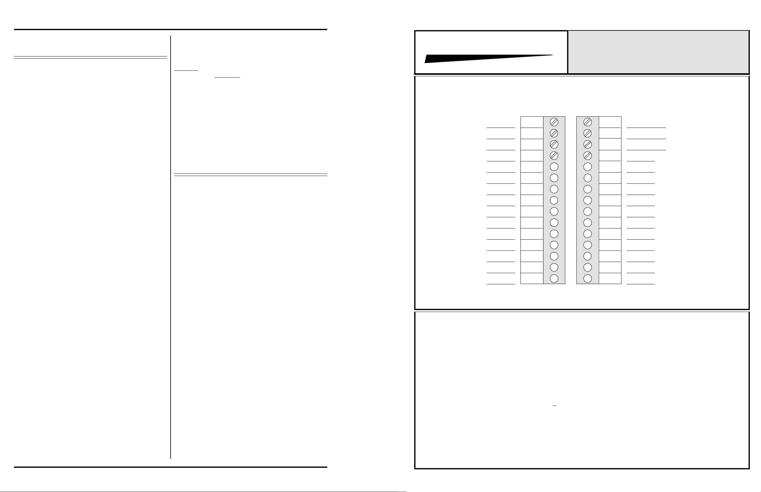
857B & 858B BACKPLANE CONNECTIONS
GROUND RELAY CONTROL PINS TO ACTIVATE RELAYS
K1 CONTROL
K2 CONTROL
K3 CONTROL
K3 ARM A
K3 ARM B
K3 ARM C
K4 ARM D
K3 N/C A
K3 N/C B
K3 N/C C
K3 N/C D
K3 N/O A
K3 N/O B
K3 N/O C
K3 N/O D
Specifications - Model 571B
Number of Relays....................
Contact Arrange-
ment...............
On Resis-
tance...........................
Contact Rat-
ings........................
Operating
Time.........................
Release
Time...........................
SPECIFICATIONS SUBJECT TO CHANGE WITHOUT NOTICE.
Power Require-
ments................
Size...........................................
16
17
18
19
20
21
22
23
24
25
26
27
28
29
30
®
CONNECTOR & PROGRAM DRAWING
1
2
3
4
5
6
7
8
9
10
11
12
13
14
15
2 Double-Pole, 1 Four-Pole
Form C
0.2 Ohm
0.3 Amp 125 VAC
0.3 Amp 110 VDC
1.0 Amp 30 VDC
5.0ms
2ms
+15-24VDC @ 60ma Per
Module
2.5"H x 8.0"D x 1.1"W
INTEGRA III SYSTEM
MODEL 571B
K1 ARM A
K1 ARM B
GROUND
K1 N/C A
K1 N/C B
K1 N/O A
K1 N/O B
GROUND
K2 ARM A
K2 ARM B
K2 N/C A
K2 N/C B
GROUND
K2 N/O A
K2 N/O B
Page 2
 Loading...