

Page 1
Protech Audio Corporation, 192 Cedar River Road, Indian Lake, New York 12842 Voice 518-648-6410 Fax 518-648-6395
PROTECH
®
INSTALLATION & OPERATION
MANUAL
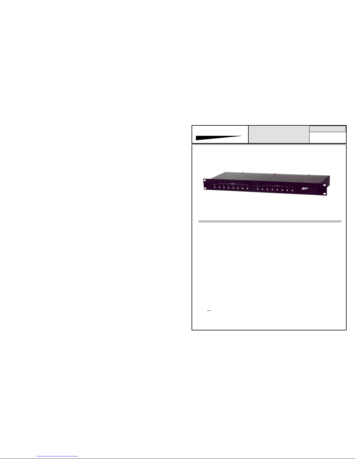
AUDIO DISTRIBUTION AMPLIFIERS
MODELS COVERED
5217
5217T
5117
5117T
Electronic or Transformer Balanced Inputs and Outputs.
All Inputs and Outputs Individually Adjustable.
The Models 5117, 5117T, 5217, 5217T audio
distribution am plifiers ar e designed fo r u se
in professional audio systems.
The application of the ADA's is found in public
address systems, communication systems, background music systems, recording systems. and
broadcast systems.
Each of the four models offers one (1) input and
seven (7) output configurations. The 5217 and
5217T offer two identical 1 x 7 sections.
The Models 5117 and 5217 have state-of-the-art
electronically balanced input(s) and outputs. The
5117T and 5217T have transformer isolated
input(s) and outputs.
The input gain stage(s) on all four models is
adjustable from 0 to 20dB of gain. Each of the
outputs has independently adjustable gain, from
infinity to 20dB of gain. Adjusting the level of any
output section does not effect the settings of any
other output. Adjusting the input stage level will
effect all of the output level settings in that
section. The 20dB of gain available at the
input stage should be used before the gain of
the output section is utilized.
Using the output gain before the input gain has
been exhausted, may result in lower headroom (less
level increase before clipping). All units are shipped
from the factory with gains adusted to unity, into a
600 ohm load.
The power supply section of all four models has
been designed to achieve the lowest possible
noise and hum specifications. The AC transformer
is a UL recognized wall mount unit. Designing
the transformer in this manner eliminates the AC
field inside the chassis, and results in greatly
improved noise and hum figures.
The power supply section also includes a rear
mounted fuseholder, a front mounted power on
indicator (green LE D ), a nd a gr o u nd lift s witch.
The switch is used to disconnect the audio
amplifier ground from earth ground, if
necessary. In almost all systems, the units will
achieve best results with the ground lift switch
in the ON position.
Each of the four models requires only a single
unit of vertical rack space. The choice of single
or dual units provides extreme circuit density in
a minimum of rack space.
1/06
www.protechaudio.com
Page 2
OUTPUT SECTION 1
OUTPUT SECTION 2
OUTPUT CONTROLS
SECTION 2
OUTPUT CONTROLS
SECTION 1
POWER ON
INDICATOR
OUTPUT SECTION 1
OUTPUT SECTION 2
POWER
SUPPLY
REAR VIEW
FRONT VIEW
INSTALLATION
The Toolbox Series Audio Distribution Amplifiers from
Protech Audio are designed to be mounted in a standard 19
inch wide EIA rack. Each of the four models requires 1.75
inches of vertical rack space. The steps for installing
the units are as follows;
Mount unit in rack, using four machine screws of sufficient
tensile strength to support unit properly.
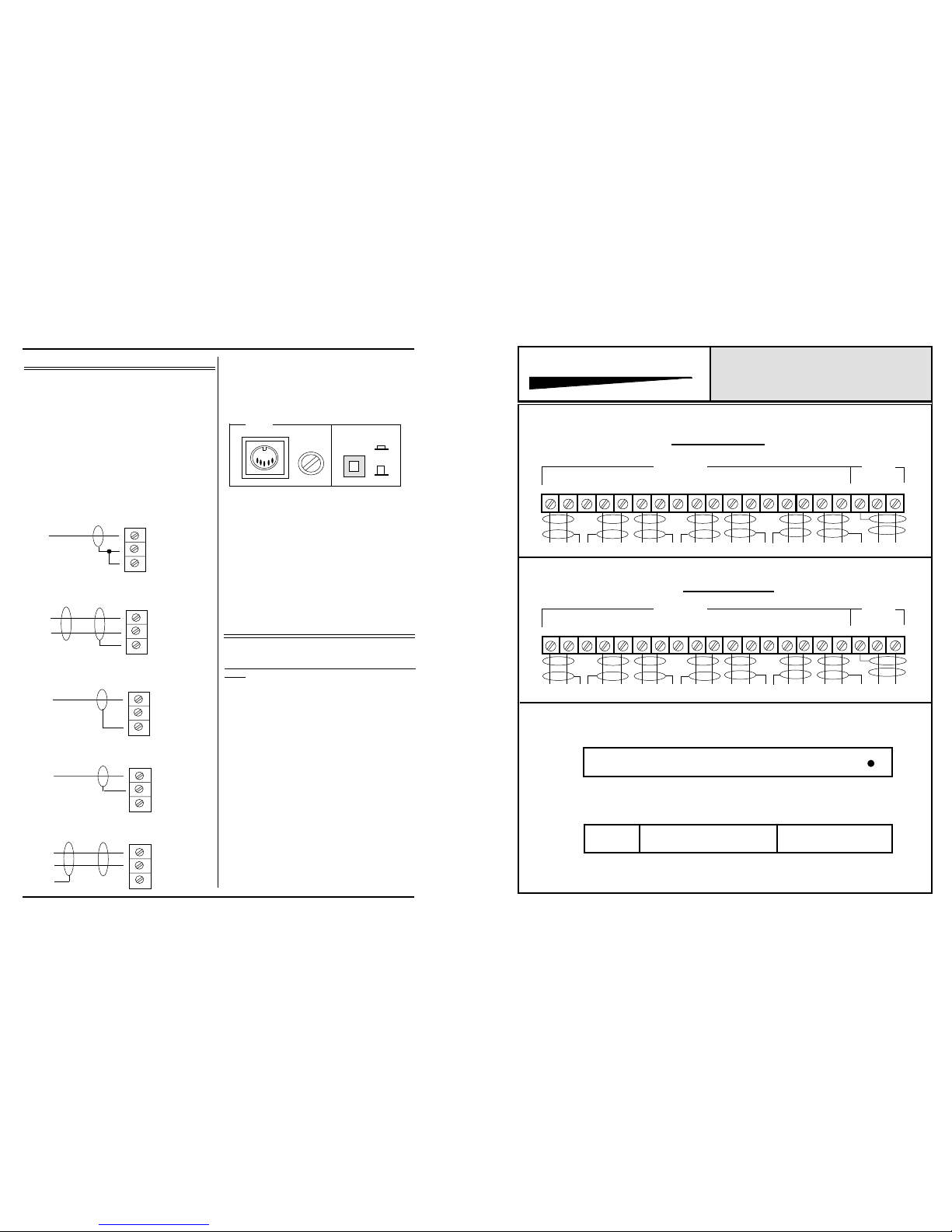
Terminate all audio inputs and outputs, using double conductor
shielded cable, as shown on facing page. The diagram on the
facing page shows balanced line configurations. For unbalanced lines terminate line HI to DA HI, and line LO to DA SH
connection;
Page 2
SH
LO
HI
UNBALANCED INPUT
CONNECTION
TOOLBOX SERIES
PROTECH AUDIO
®
MODELS 5117, 5217, 5117T, 5217T
CONNECTOR & LAYOUT DRAW-
ING
The wall mount power transformer plugs into the rear power
connector marked 20VAC. Plug transformer jack into chassis
connector first. Then plug wall transformer into three prong AC
outlet.
OFF
ON
GROUND
LIFT
1 AMP
SLO-BLO
20 VAC
Make sure ground lift switch is in the on position.
Check front panel power indicator (green LED) for proper
illumination.
SH
LO
HI
BALANCED INPUT
CONNECTION
SH
LO
HI
UNBALANCED OUTPUT
CONNECTION (Electronic)
SH
LO
HI
BALANCED OUTPUT
CONNECTION
ALIGNMENT
All four models have been shipped from the factory adjusted
for unity gain. The input is adjustable from 0 to 20dB of gain.
THIS GAIN SHOULD BE USED BEFORE THE OUTPUT
GAIN.
Each output is individually adjustable from infinity (completely
off) to 20dB of gain. The input gain trimpot should be used to
adjust the output setting to the desired level. If the input gain
trimpot is adjusted to it's maximum clockwise position (maximum gain) and the output level is still not high enough, the
output gain trimpot may be used to add additional gain.
Adjusting the individual output gain trimpot will not effect the
any other output level setting.
LO HI
4
56
7
32
1
OUTPUTS
INPUT
SH LO HI LO HI SH LO HI LO HI SH LO HI LO HI SH LO HI
LO HI
4
56
7
32
1
OUTPUTS
INPUT
SH LO HI LO HI SH LO HI LO HI SH LO HI LO HI SH LO HI
SH
LO
HI
UNBALANCED OUTPUT
CONNECTION (Transformer)
 Loading...