

Page 1
PROTECH
MODELS COVERED
517B
®
INTEGRA III SYSTEM
1/06
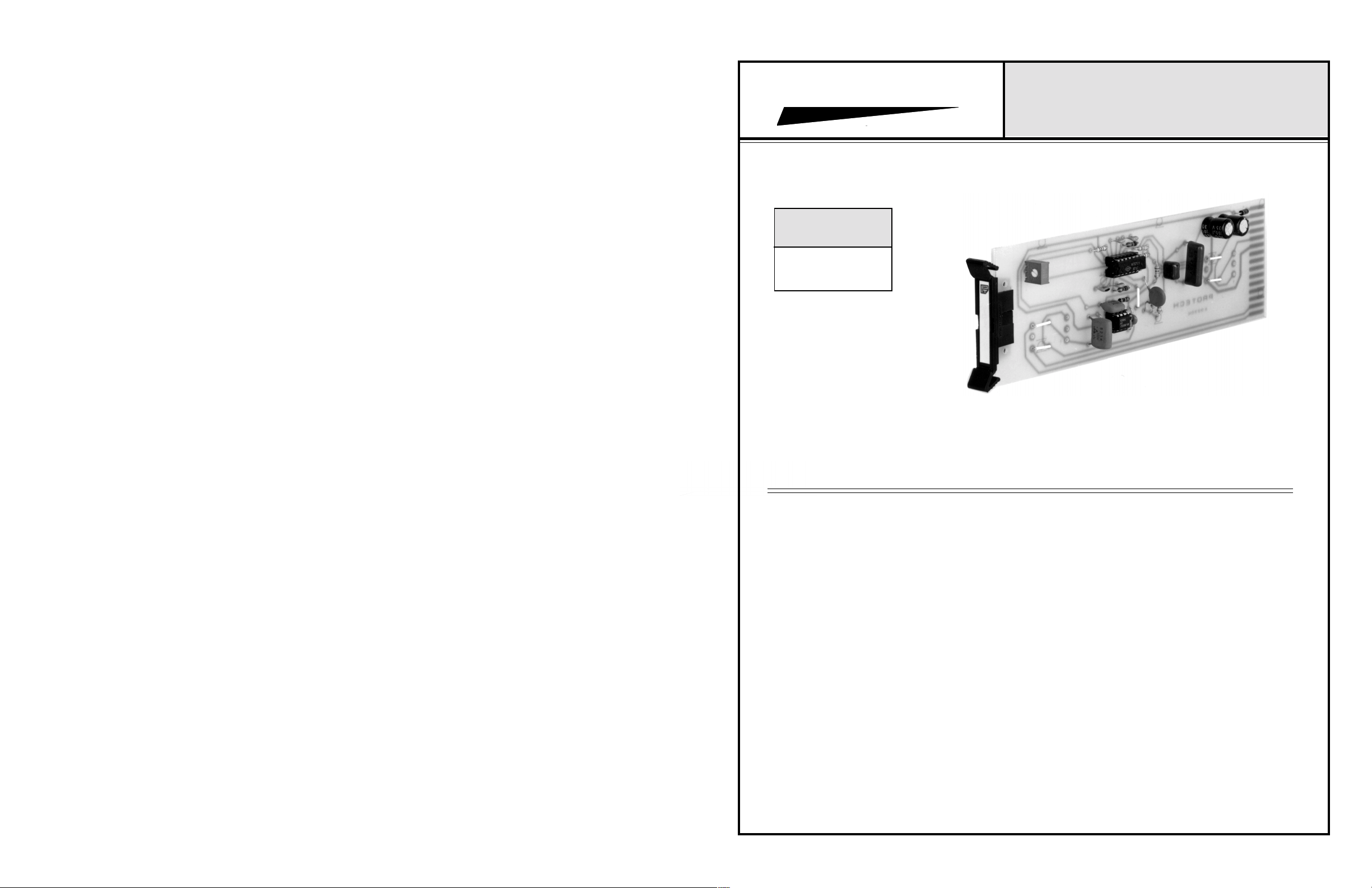
517B
25 HERTZ NOTCH FILTER CARD
INSTALLATION & OPERATION MANUAL
Model 517 Shown
www.protechaudio.com
The Model 517B Notch Filter Card is designed
for use in professional audio applications, which
require constant, automatic supervision of audio
equipment and circuits.
The Model 517B Notch Filter is used in conjunction with the Model 562B 25Hz Oscillator card
and the Model 685 Tone Supervisor card.
The Model 517B Notch Filter card is used to
remove any 25Hz content from program or page
material. The program material is fed thru the
notch filter card. The notch filter allows all of the
program material to pass thru, without distortion, except the 25Hz content. The 25Hz content
is attenuated 50dB. This insures that no out-ofphase 25Hz audio can cause false triggering at
the Model 685 Tone Supervisor card.
The Model 685 Tone Supervisor card is designed to detect the presence of a 25Hz signal in
a complex audio program. If the 25Hz tone
should stop, or fall below a certain level, the
detector card will deactivate a relay, which is
wired to an alarm device.
The Model 562B provides a constant level 25 Hz
signal at +4dBm. The frequency and level are
fixed via circuit design, in order to allow the
Model 562B to serve as both a signal source,
and a reference level. Typical applications are
multi-zone public address systems, intercoms,
paging systems, training systems, and monitoring systems.
The actual application is found in buildings such
as airports, factories, courthouses, casinos, convention centers, libraries, military facilities, racetracks, and corporate boardrooms.
The INTERGRA III card frame system also
features mixers, power amplifiers, remote level
controls, distribution amplifiers, and switching
cards, to facilitate complete system design. Application notes showing typical system layouts
are available for all INTEGRA III modules.
For additional information, or applications assistance, contact:
SALES ENGINEERING
Protech Audio Corporation, PO Box 597, 192 Cedar River Road, Indian Lake, New York, 12842, Voice 518-648-6410 Fax 518-648-6395
Page 2
INSTALLATION
The 517B is designed to be mounted in the Mode 857B or
Model 858B Card Frame Package. The Model 857B Card
Frame Package will accomodate up to 10 cards, using an
external power supply (Model 66708). The Model 858B
Card Frame Package will accomodate 9 cards, and is
supplied with a plug-in power supply card.
The determination as to which backplane assembly to use
in your project, was made prior to our factory receiving the
order. The backplane assembly you have received will
accommodate the group of cards you or your designer
have specified.
The actual steps necessary for installation of the 517B
Notch Filter card, are comparable to those necessary for
and of the 600 series cards. They are as follows:
1 - Mount the card frame in an appropriate EIA 19" width
rack, using 4 screws of sufficient strength to provide
secure mounting.
2 - A determination has been made as to which type of
power supply will be used on your system. Follow the
instructions for the type of power supply you will be
installing.
4- Unpack each individual card, inspect for shipping
damage, and assuming none is found, slide the card
half-way into the appropriate slot. After all cards have
been installed
card at a time and turn on the power supply, unplug the
card and recheck terminations. If n o loading is noticed,
continue inserting each card in the card frame, checking
power supply loading as each card is plugged in. When all
the cards have been plugged in, the installation is
complete, and all the remains is the alignment.
half-way into the card frame, plug in one
ALIGNMENT
There are no field adjustments necessary to operate the
Model 517B Notch Filter card. The operation of the card is
automatic. The notch alignment trimpot on the card is
adjusted at the factory prior to shipment. This adjustment
determines the amount of attenuation provided by the notch
filter circuit. The card has been shipped with the notch
aligned for maximum attenuation.
The alignment procedures for Integra III System cards,
differ from card type to card type. Therefore it is necessary
to consult the alignment procedure for each type of card
being installed, to porperly align a card frame using different
card types.
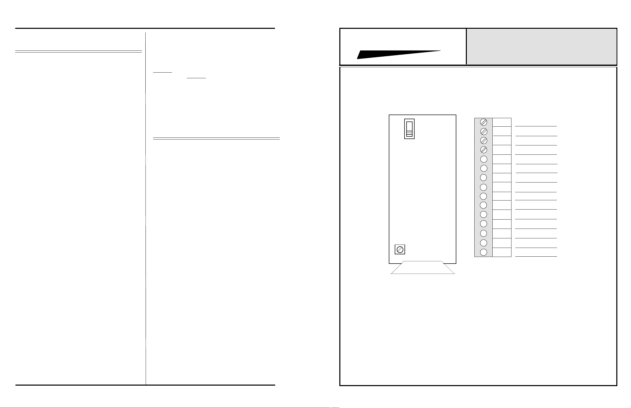
PROTECH
Mic
Line
®
CONNECTOR & TRIMPOT DRAWING
857B & 858B BACKPLANE CONNECTIONS
INTEGRA III SYSTEM
MODEL 517B 25Hz NOTCH FILTER
1
2
3
INPUT LO
INPUT HI
GROUND *
4
5
6
7
8
9
10
11
12
13
EXTERNAL POWER SUPPLY. If an external power
supply is to be used, terminate the proper supply connections to pins 1, 2 & 3, of card slot No. 10, as shown in the
card frame layout drawing, and the card connection drawing shown on the facing page. Turn on the power supply,
and using a DC voltmeter, check for correct voltage and
polarity at pins 1, 2, & 3 of card slot number 1.
INTERNAL POWER SUPPLY. If a plug-in power supply
card is to be used, plug in the supply card, and check for
proper illumination of the two green LEDs on the front of
the power supply card.
3 - Terminate all audio input and output connections, using
the card connection drqwing on the facing page. Double
conductor shielded cable is recommended for all audio
connections.
Page 2
NOTCH ALIGN.
CARD HANDLE
14
15
OUTPUT HI
OUTPUT LO
 Loading...