

Page 1
PROTECH
www.protechaudio.com
®
1/06
INSTALLATION & OPERATION MANUAL
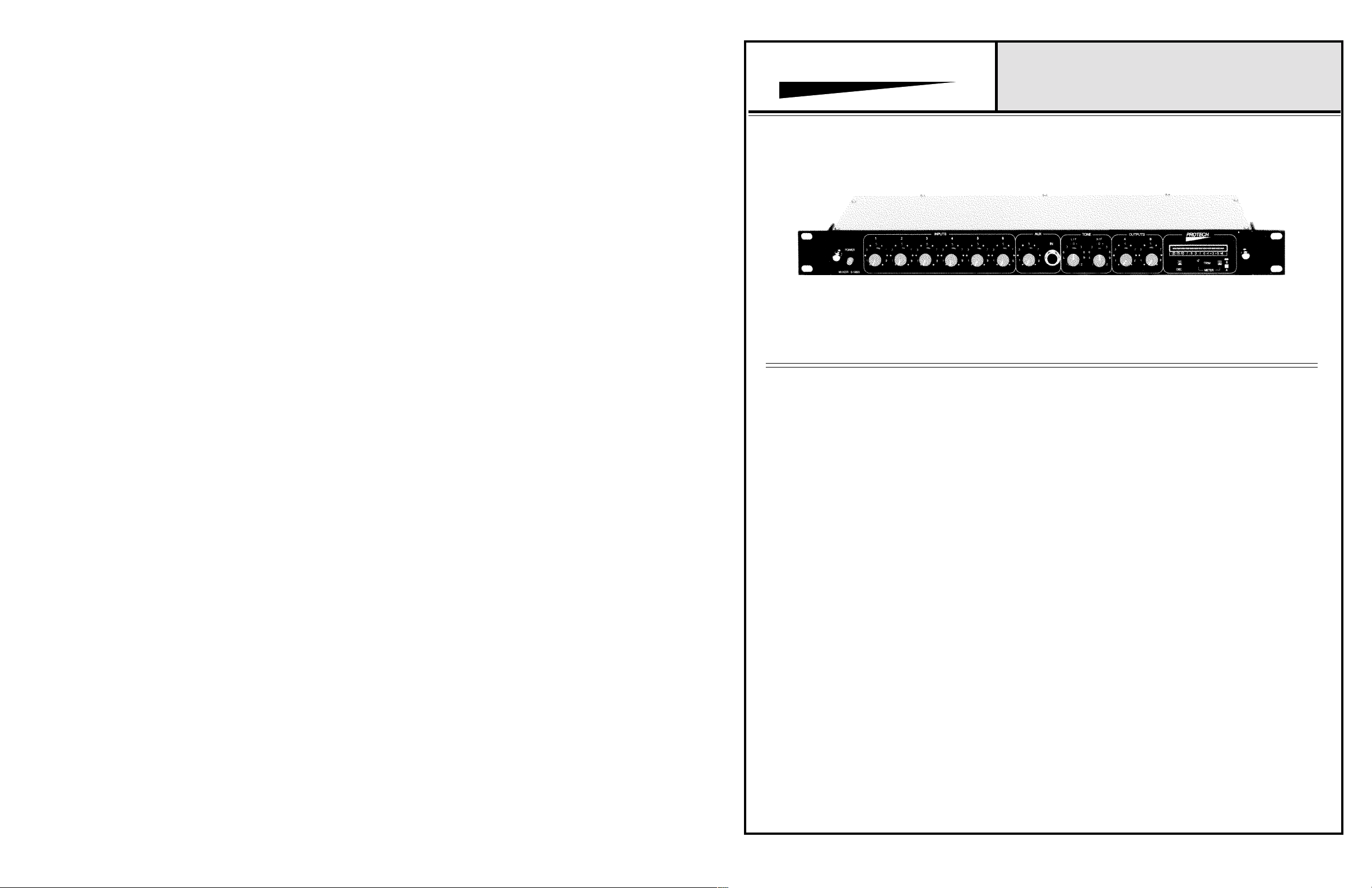
MODEL 51003
AUDIO MIXING SYSTEM
PHOTOGRAPH
The Model 51003 Audio Mixing System is designed for
smaller installations, th at e xp ec t t o e xp and in th e near
future. The 51003 incorporates most features that are
required in a professional installation. The unit includes the
following features;
Microphone and/or line level inputs, all transformer isolated.
Phantom power capability selectable for each input.
Selectable gain structures on each input (4 settings).
Low-cut filters, selectable on each input.
Priority setting for channel 1, with automatic override, or,
hard wired to external switch for muting channels 2 thru
AUX.
Adjustable mix level for each input, including AUX.
AUX input hardwired on rear terminal, with front panel jack
to bypass rear input and allow access to mixing buss.
Mixing buss link capability, to allow additional inputs.
Effects send/receive link.
Bass & Treble Controls, with switch selectable defeat mode.
Limiter, with switch selectable defeat mode.
Two transformer isolated outputs, with switch selectable
remote control of output two.
Metering of outputs A/B, with adjustable meter trim
Built-in oscillator to allow quick set-up
In addition to the many features already listed, the Model
51003 is designed to allow the entire PC assembly to unplug
from the front of the chassis to facilitate quick changeovers.
And the UL approved wall mount transformer helps the unit
to provide superior specifications.
The architectural design of the Model 51003 is to allow the unit
to serve as the heart of a small audio system, and still not
become obsolete when the designer wishes to add additional
equipment to the system. For instance, the defeat switches
on both the tone controls, and the limiter, will allow
future addition of an equalizer and/or compressor/
limiter. The defeat switches are activated, and the effects
send is used to introduce these additional pieces of
equipment into the system, without loosing the main
mixing and distributing features of the Model 51003.
The input section has a large number of user definable
features, in order to accomodate the variety of requirements
that may come up in a small installation, such as a Houseof-Worship. The electronics may be unplugged from the
front, and re-configured in a matter of moments, to allow
multiple uses of the sound system.
The built-in oscillator, and the LED bargraph metering
of both outputs, helps make the realignment process, after
changeover, as easy as possible. By making use of these
features, the audio engineer can make pr ecise and
repeatable alignments in a matter of minutes.
This installation and operation manual is designed to
help the user become acquainted wi th t he many features
of the Model 51003, and how best to make use of them.
The Model 51003 Audio Mixing System is a perfect
companion to other Protech Audio products, such a s the
Model 5117T Audio Distribution Amplifier, or the Model
65302B Ambient Sensing Level Control.
Protech Audio Corporation 192 Cedar River Road, Indian Lake, New York 12842 Voice 518-648-6410 Fax 518-648-6395
Page 2

TABLE OF CONTENTS
Page 1 Page 2 Page 3 Page 4 Page 5 Page 6 Page 7 Page 8 Page 9 Page 10 Page 11 -
Table of Contents.
Block Diagram.
Input & Output Section, Standard Setup and Wiring.
Input & Output Section Mechanical Drawing.
Using Special Features, Setup.
Using Special Features, Setup.
Using Special Features, Setup.
Setup, As Shipped
Specifications.
Schematic, Input Section.
Schematic, Auxillary Input Section.
Page 12 Page 13 Page 14 Page 15 Page 16 Page 17 Page 18 -
Schematic, Priority Circuit.
Schematic, Summing Amplifier.
Schematic, Limiter Circuit.
Schematic, Output Section.
Schematic, Tone Control Circuit.
Schematic, Oscillator Circuit.
Schematic, LED Display Circuit.
Schematic, Power Supply Cir cuit.
Page 3

Treble
EQ
Bass
Output
Channel A
Output
Channel B
Trim
LED
Meter
Remote
Control
Effects
In/Out
In/Out
Mix Buss
Buffer
Buffer
Summing
Amplifier
EQ Defeat
Mute
Circuit
Switch
Limiter
Output
Channel A
Drive Amp
Master
Switch
Limiter Defeat
BST.
Output
Channel B
Drive Amp
VCA
Control
Front Panel
CH. A
CH. B
Mute
Automatic
Protech Audio Corporation
Model 51003 Audio Mixer Block Diagram
Channel
4 Position
Slide
Channel
Input
Level
Gain Select
DIP Switch
Switch
Cut/Flat
Power
Phantom
Mic/Line
Input
1
Cut/Flat
Power
Phantom
Mic/Line
Input
2
Cut/Flat
Power
Phantom
Mic/Line
Input
1 KHz
Tone Oscillator
4
Cut/Flat
Power
Phantom
Mic/Line
Input
5
Cut/Flat
Power
Phantom
Mic/Line
Input
External
Mute
Switch
6
Panel
Front
Jack
AUX
Input
Cut/Flat
Power
Phantom
Mic/Line
3
Input
Page 4

HI
LO
SH
HI
LO
SH
After input and output section have been
configured, proceed with installation of unit
in rack.
Slide PC assembly back into chassis until
fully seated in mating connectors ( front
panel should be flush with mounting brack-
ets).
Mount unit in rack, using four machine
screws of sufficient tensile strength to
support unit properly.
With unit firmly on workbench, loosen
the two thumbscrews on each end of
front panel, and slide PC assembly out
OUTPUT SECTION
The following configuration and installation
steps should be done only after the input
section has been configured. The steps are
as follows;
1 -
OUTPUT SECTION CONFIGURATION
Terminate all audio inputs and outputs, us-
ing double conductor shielded cable, as
of chassis.
BALANCED OUTPUT CONNECTION
shown below, and in input section.
If necessary, slide the LOC/RMT switch
(#5) to RMT position to allow remote
2 -
control of the Channel B output level.
If necessary, slide the EQ switch (#6) to
3 -
the OUT position to bypass the tone
control section.
UNBALANCED OUTPUT CONNECTION
If necessary, slide the LIM switch (#7)
to the OUT position to bypass the lim-
iter section.
4 -
Turn OUTPUT control knobs (#8) fully
counterclockwise.
Check to confirm that the TONE switch
(#9) is in the OFF position.
5 -
6 -
Plug wall mount transformer DIN connector
into AC connector on rear of chassis. Plug
wall mount transformer into AC receptacle.
20 VAC
This concludes the configuration options for
the output section. Refer to the input section
for input configuration options.
This concludes the connections for the
Model 51003.
51003 MIXER
HOW YOUR MIXER
WAS CONFIGURED
AND SHIPPED
After input and output section have been
configured, proceed with installation of
unit in rack.
Slide PC assembly back into chassis until
fully seated in mating connectors (front
panel should be flush with mounting
brackets).
Mount unit in rack, using four machine
SH
LO
HI
screws of sufficient tensile strength to sup-
port unit properly. Terminate all audio
inputs and outputs, using double conduc-
tor shielded cable, as shown below and
BALANCED INPUT CONNECTION
in output section.
LO
HI
UNBALANCED INPUT CONNECTION
SH
not needing
HI
SH
AUXILLARY INPUT CONNECTION
This concludes the connections for the
input section. Refer to the output section on
this page, for output connection informa-
SWITCH POSITION
GROUND LIFT................................................................ON
MIC. / LINE SWITCH.......................................................MIC
PRIORITY (INPUT #1).....................................................OFF (MANUAL REMOTE)
EQ SWITCH ...................................................................IN
COMPRESSOR................................................................OUT
OUTPUT (B) RMT./LOC...................................................LOCAL
tion.
4 POS. DIP SWITCH
A = PHANTOM POWER................................................OFF
B = GAIN 1.....................................................................ON
C = GAIN 2.....................................................................ON
D = BYPASS, L/F ROLL OFF.........................................ON
LED DISPLAY.................................................................0 VU = 0dBv OUTPUT
INPUT SECTION
The Model 51003 Audio Mixing System is
designed to mount in a standard 19" wide
EIA rack. Each unit requires 1.75" of ver-
tical rack space. Care should be taken not to
mount the unit next to power supplies, power
amplifiers, or other equipment which gen-
erate strong AC fields. The steps for install-
ing the unit are as follows;
With unit firmly on workbench, loosen
two thumbscrews located on each end of
front panel, and slide PC assembly out of
chassis.
Check that ground lift switch (#1) is in
the on position.
Slide Mic/Line selector switches (#2) to
the desired positions.
Slide DIP switch (#3) position A to on
position for each input needing Phantom
1-
INPUT SECTION CONFIGURATION
2-
3-
4-
Power.
Slide DIP switch (#3) position D to off
5-
position for each input
LOW-CUT filter.
If required, slide DIP switch (#3) posi-
tions to off position for reduced gain on
6-
each channel (see chart on page 5).
If required, slide priority switch (#4) to
7-
IN position to activate automatic priority
feature.
This concludes the configuration options for
the input section. Refer to the output section
on this page, for output configuration
options.
Page 5

SPECIAL FEATURE SECTION
FEATURE SETUP
AUXILLARY INPUT
The auxillary input is wired thru the rear barrier terminal, and is normalled thru the front panel phone jack.
Plugging a phone plug into the front panel jack disconnects the rear terminal auxillary input. It also allows
audio on the phone plug to enter the mix buss thru the front panel AUX pot.
Wiring for the front panel jack is as follows;
TO AUX LEVEL CONTROL
FROM REAR BARRIER INPUT
OUTPUT TRANSFORMERS
LINELINE
DIST.
ADJUST
LIMITER
ADJUST
#7
LIM
OFF
ON
RMT
EQ
#6
#9
#5
IN
OUT
A/B
METER
METER
OSC
LOC
MASTER
TREBLE
BASS
TRIM
B
A
#8
0dB
20dB
15dB
25dB
OFFONOFF
B C Gain
OFF
LINE
LEVEL
35dB
ON
OFFONON
57dB
50dB
60dB
PRIORITY INPUT ON CHANNEL 1
The priority feature on channel 1 disconnects all other inputs from the summing buss, with the exception of
the summing buss link on the rear barrier. The priority feature may be used in one of two modes;
Automatic = any audio applied to the #1 input will automatically activate the priority feature,
Manual = a closure applied to the rear barrier terminal will activate the feature.
To use the automatic function, loosen the two thumbscrews and remove the electronic section from the
chassis.
Slide thepriority switch (see pc layout drawing) to the ON position.
Slide electronic section back into chassis, making sure pc board is seated properly in mating connectors, and
tighten thumbscrews.
To use the manual mode, apply a closure to the rear barrier terminal as shown below.
B
LO HI
OUTPUTS
SH
A
HI
LO
RMT
HI ARM
SUM
IN
LO
OUT
SH
AFX MUTE
OUT
IN
SW
AUX
IN
HI SH
REMOTE
CLOSURE
LINE
LINE
LINE
MIC / LINE SWITCHES
MIC MIC MIC MIC MIC
MIC
LINE
#2
GND ON
GND LIFT
INPUT SELECT SWITCHES
#1
AUX JACK
ON
#4
PRIORITY
OFF
OFFONOFF
B C Gain
OFF
ON
OFFONON
MIC
LEVEL
D
C
B
A
ON
OFF
#3
ON/OFF
POWER
INPUT LEVEL CONTROLS
1 2 3 4 5 6 7
DIP SWITCH LEGEND:
A = PHANTOM POWER
D = BYPASS, L/F ROLL OFF
C = GAIN SELECT
B = GAIN SELECT
Page 8
9/94
LED
Page 6

SPECIAL FEATURE SECTION
SPECIAL FEATURE SECTION
FEATURE SETUP
USING THE INTERNAL OSCILLATOR FOR SETUP.
Turn all input pots completely counterclockwise.
Turn both output pots completely counterclockwise.
Set meter select switch to output A.
Depress oscillator switch to turn on oscillator.
Slowly turn output A pot clockwise until a OdB reading is attained on the meter.
Set meter select switch to output B.
Slowly turn output B pot clockwise until a 0dB reading is attained on the meter.
Depress oscillator switch to turn off oscillator.
The output gain sections are now set for unity gain, and the input pots may be used to set individual
input channel gain settings.
FEATURE SETUP
EFFECTS IN/OUT
Remove jumper from barrier terminal.
Wire effects unit to barrier terminal as shown.
OUTPUTS
B
LO HI
IN FROM EFFECTS UNIT OUTPUT OUT TO EFFECTS UNIT INPUT
A
SH
HI
LO
RMT
HI ARM
SUM
IN
LO
OUT
SH
AFX MUTE
OUT
IN
SW
AUX
IN
HI SH
REMOTE CONTROL OF CHANNEL B OUTPUT LEVEL
Loosen two thumbscrews on either side of front panel, and remove electronic assembly from front of
chassis.
Slide LOC/RMT switch to RMT position (See PC Output Layout Drawing).
Slide electronic section back into chassis, making sure pc assembly is properly seated in mating connectors.
Tighten two thumbscrews.
Wire external pot (10K Ohms minimum) to rear barrier terminals as shown below.
B
LO HI
OUTPUTS
SH
A
HI
LO
RMT
HI ARM
SUM
IN
LO
OUT
SH
AFX MUTE
OUT
IN
SW
AUX
IN
HI SH
MIX BUSS IN/OUT
The summing buss link allows access to the summing buss thru a 10K resistor. This allows the link to
function as either an input, or an output, when used with unbalanced line level signals.
B
LO HI
OUTPUTS
SH
A
HI
LO
RMT
HI ARM
SUMMING BUSS ACCESS, IN OR OUT
SUM
IN
LO
OUT
SH
AFX MUTE
OUT
IN
SW
AUX
IN
HI SH
Page 6
9/94
Page 7
9/94
 Loading...