

Page 1

Location of pad slide switches and RED push-on gain jumpers.
PROTECH
®
1/08
MODEL 5044
INSTALLATION & OPERATION MANUAL
MATRIX MIXER
Notes:
Slide switch
Input 1
Pad Out
Pad In (-10dB)
RED
Push-On
Jumper
Input 1
Slide switch
Input 2
Pad Out
Pad In (-10dB)
RED
Push-On
Jumper
Input 2
Top View With Cover Removed
Slide switch
Input 3
Pad Out
Pad In (-10dB)
RED
Push-On
Jumper
Input 3
Slide switch
Input 4
Pad Out
Pad In (-10dB)
RED
Push-On
Jumper
Input 4
Power
Supply
section
FEATURES
Transformer Balanced Inputs.
Transformer Balanced Outputs.
Adjustable Mixing Level(s).
Individual Mutes For Each Output
Switchable 10dB Pad and 10dB Gain Setting
External UL Listed Power Transformer For Lowest Possible Noise.
www.protechaudio.com
- Page 4 -
The Model 5044 Matrix Mixer is designed to
provide the system designer, and audio contractor,
with a matrix mixer that provides adjustable output
levels for each line level input signal to each output.
The 5044 will accomodate up to 4 inputs and
provides 4 separate outputs each with it's own
custom signal mix.
Each input is balanced bridging transformer isolated. Each output is low impedance transformer
isolated capable of driving loads as low as 600
ohms.
Each input level is adjustable from off to +25dBv to
each output, relative to the input signal level. Adjustment of an input level to any output will not effect
levels adjusted to other outputs.
Each output contains an externally controlled mute
switch for each input signal to allow mixes to be
changed from other control devices.
Typical mixes can include any or all input signals.
Protech Audio Corporation PO Box 597, 192 Cedar River Road Indian Lake New York 12842 Voice 518-648-6410 Fax 518-648-6395
The Model 5044 can also be used as a 4 channel line
amplifier.
Actual installations include such facilities as factories,
convention centers, racetracks, arenas, corporate
communication centers, airports, mass transit systems, and broadcast centers.
Every circuit in the Toolbox Series has been meticulously engineered, to achieve maximum reliability.
The power supply section of all Tool Box Series
audio devices, incorporates a UL recognized power
transformer. By mounting the AC power transformer
outside of the audio chassis, the Toolbox Series
audio devices achieve the lowest possible hum specification. Fusing is accomplished thru the use of a
standard, easily available 3AG size Slo-Blo fuse,
with the fuseholder mounted on the rear of the
chassis. A ground lift switch is mounted on the rear
of the chassis, to provide additional installation flexibility.
Page 2
INSTALLATION
The Model 5044 Matrix Mixer from Protech Audio is designed
to be mounted in a standard 19 inch wide EIA rack. Each
unit requires 1.75 inches of vertical rack space. The steps
for installing the unit are as follows;
The wall mount power transformer plugs into the rear power
connector marked 16VAC. Plug transformer jack into chassis
connector first. Then plug wall transformer into three prong AC
outlet.
PROTECH AUDIO
®
TOOLBOX SERIES
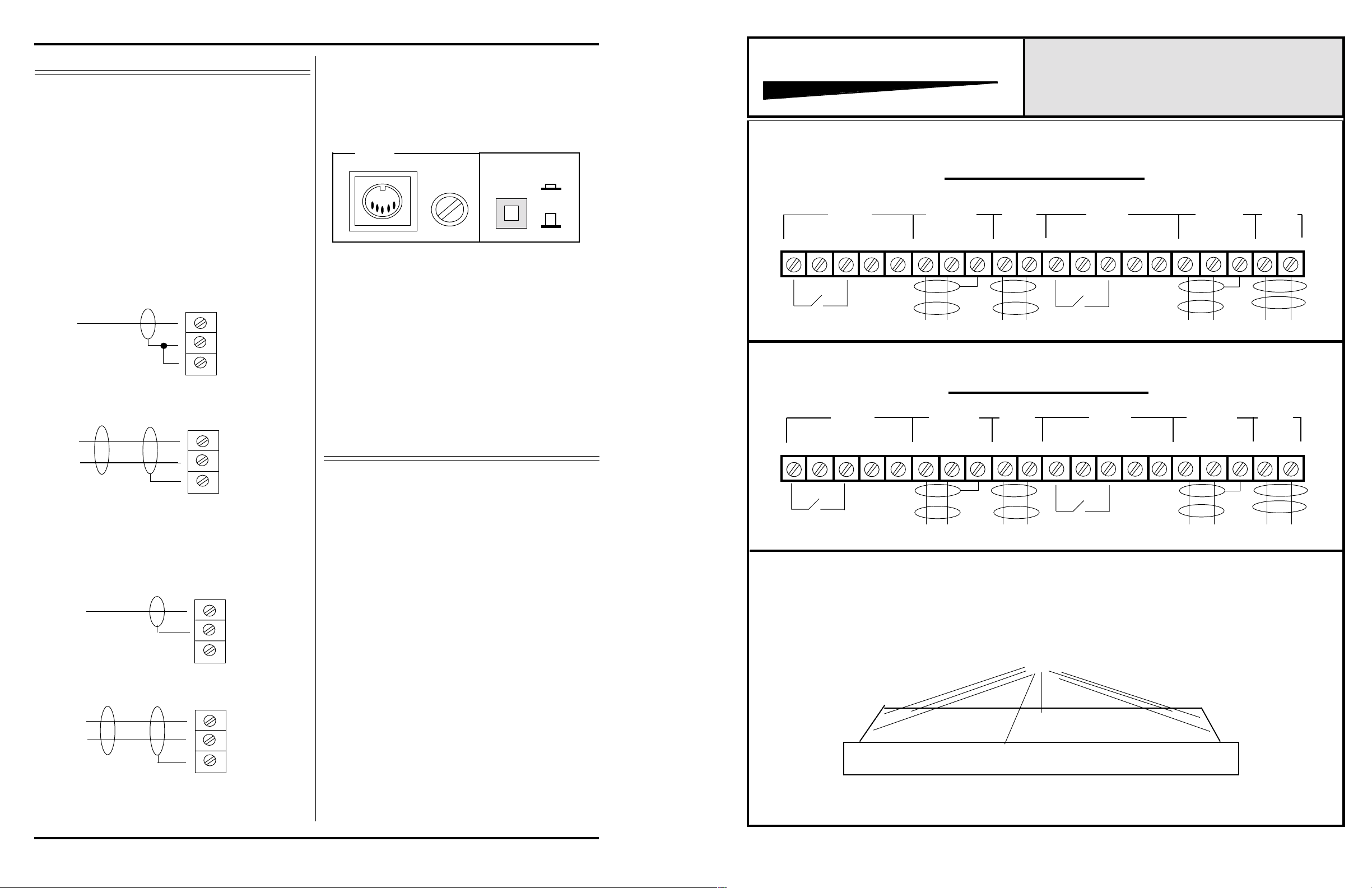
MODEL5044 MATRIX MIXER
CONNECTOR & LAYOUT DR A W I N G
Mount unit in rack, using four machine screws of sufficient
tensile strength to support unit properly.
Terminate all audio inputs and outputs, using double conductor
shielded cable, as shown on facing page. The diagram on the
facing page shows balanced line configurations. For unbalanced lines terminate as shwon below
UNBALANCED INPUT
CONNECTION
HI
LO
SH
BALANCED INPUT
CONNECTION
HI
LO
SH
18 VAC
1 AMP
SLO-BLO
GROUND
LIFT
ON
OFF
Make sure ground lift switch is in the on position.
Check front panel power indicator (green LED) for proper
illumination.
ALIGNMENT
All four models have been shipped from the factory adjusted
for unity gain. Applying a signal to input #1 will result in the
same level signal appearing on each output. This is true of any
input to any output.
Adjusting the input #1 trimpot on Output#1 section will not
effect the input #1 signal on outputs 2 thru 4. Each input signal
should be adjusted while monitoring each output individually.
MUTES
43
External switch closure
To Activate Mutes (Typical)
43 2
External switch closure
To Activate Mutes (Typical)
SH
MUTES
SH LO HI SH LO HI
OUTPUT SECTIONS 1 & 2
1
OUTPUT
#2
LO HI
INPUT
#2
SH LO HI
MUTES
43 2
External switch closure
To Activate Mutes (Typical)
SH
OUTPUT
#1
1
LO HI SH LO HI2
INPUT
#1
OUTPUT SECTIONS 3 & 4
OUTPUT
#4
1
INPUT
#4
43 2
External switch closure
To Activate Mutes (Typical)
MUTES
SH
1
OUTPUT
#3
LO HI
INPUT
#3
SH LO HI
UNBALANCED OUTPUT
CONNECTION (Transformer)
HI
LO
SH
BALANCED OUTPUT
CONNECTION
HI
LO
SH
Each input section contains a slide switch that controls a 10dB
pad. The Model 5044 is shipped with the pad in place. If more
gain is required it is necessary to remove thecover to access the
pad slide switches. See page 3 for cover removal instructions.
Each input section also includes a push-on RED jumper that,
when in place, provides 10dB of gain. Removing the jumper will
reduce the input gain by 10dB. The Model 5044 is shipped with
the jumper in place.
See page 4 for pad switch and jumper locations.
Page 2
If additional level adjustments are required, beyond the range of individual gain
controls, remove 8 cover screws to access pad slide switches and RED push-on
gain jumpers.
1/08
 Loading...