

Page 1
MODELS 2004 & 2008
DUGAN AUTOMATIC MIXERS
INSTALLATION & OPERATION MANUAL
The Protech Audio Models 2004.2008 Automatic Microphone Mixers are designed to be the best operating, most
transparent auto-mixers, for rental and portable applications as well as small venues. Both the 2004 and 2008
feature patented adaptive proportional gain sharing
control circuitry designed by Dan Dugan, the inventor
of automatic mixing. This operating system results in the
best, most transparent automatic mixing to be found
anywhere. Unlike gated mixers, or quasi-Dugan mixers,
the 2004 and 2008 operate on an elegantly simple principle; each individual input channel is attenuated by an
amount, in dB, equal to the difference, in dB, between that
channel's level and the sum of all channel levels. The levels
are varied on a continuous basis, with no on-off actions, or
abrupt gain changes.
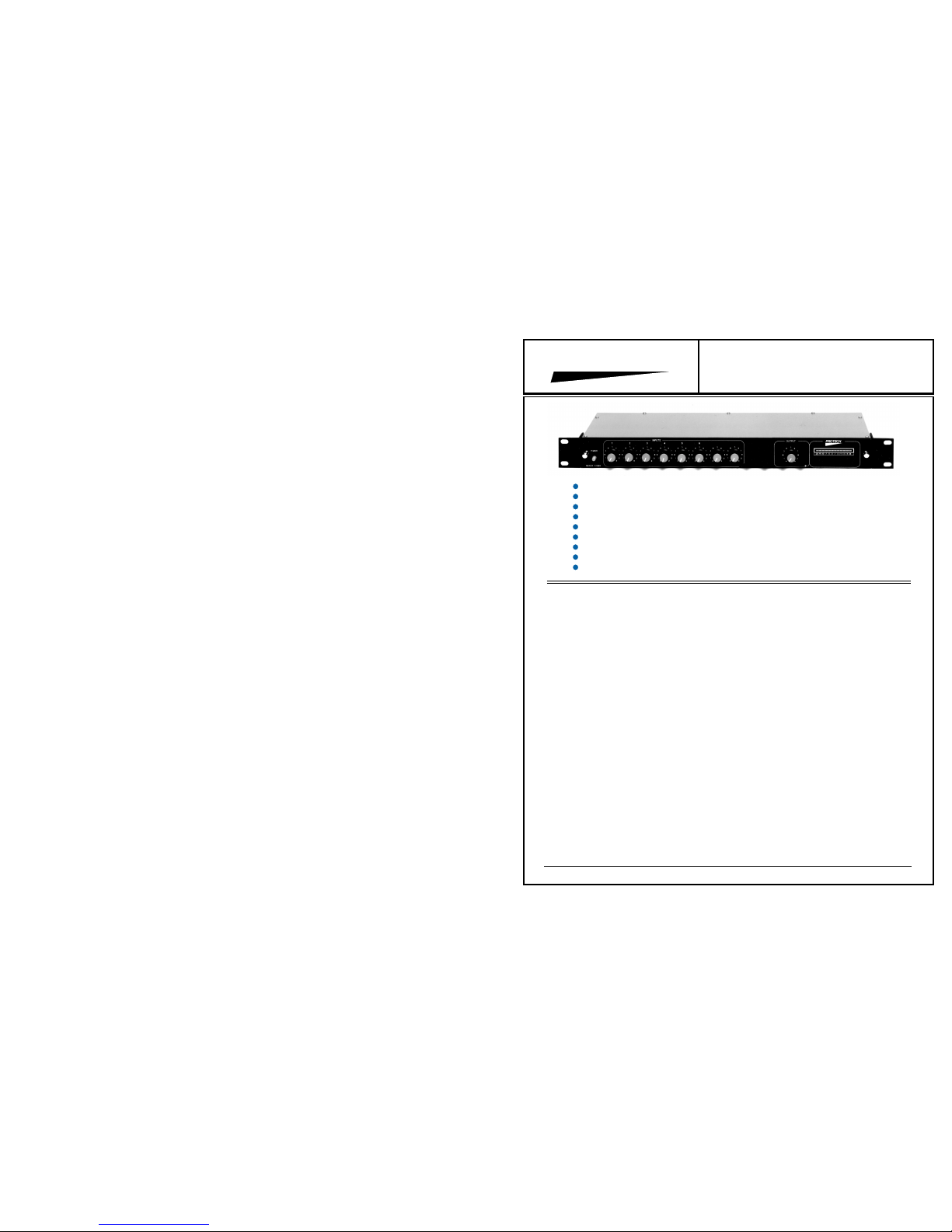
The 2008 features 8 switchable microphone/line level
inputs. The model 2004 features 4 similar inputs. Two
units may be linked together to create up to 16 inputs.
Both units feature a unique works-in-a-drawer constructi o n . Access t o al l s witches and push-on jumpers used
to configure various features, is achieved by loosening
the two thumbscrews located on each side of the front
panel, and sliding the entire electronics out of the chassis.
This easy access allows complete reconfiguration in just
minutes.
In addition to the input mode (mic/line) switch located at
each input, the gain of each input is configurable, via a
push-on jumper, to allow superior signal-to-noise opera-
tion. Moving the jumper over one pin changes the input
gain from 30dB to 50dB.
A bi-color LED is used to indicate signal presence and clip
threshold. Unlike other units, the clip indicator on the
Model 2008 indicates clipping of the summing buss, not
just an input, since it is possible to clip a summing bus,
without clipping an input.
Internal 15 volt phantom power is selected, on a channelby-channel basis, via a push-on jumper. When the input
mode slide switch is placed in the line position,
phantompower will automatically be disconnected, preventing damage to line level devices.
The Models 2004 and 2008 also feature assignable group
mute function. Each input may be assigned to the mute
buss via an eight position DIP switch. Turning on a given
switch will assign that channel to the group mute.
Grounding the group mute control pin will mute the assigned channels.
The output level of the automixers may be controlled via
the front panel output potentiometer, or, assigned to a
remote potentiometer, via an on-board slide switch.
Both units have been designed with the operator in mind.
Control features allow the operator to attend to other
functions, without the need to continuously "ride gain".
For additional information on the model 2004 and 2008, or
the Models 2000 Boardroom Automixer, and 2000-C Courtroom Automixer, contact: Applications Assistance
PROTECH
®
1/06
Automatic Mixing with Dugan Speech System.
4/8 Mic/Line Inputs With Selectable Gain Structures.
Phantom Power Capability On Each Input
Clip Indicator For All Inputs
Assignable Group Mute Per Input
12 Segment LED Metering of Output Level
Remote Gain Control Capability On Master Output.
Linkable for More Inputs
U.S. Patents 3,992,584, & 4,864,627
*
*
*
*
*
*
*
*
*
IOM2008.PM6
www.protechaudio.com
Protech Audio Corporation, PO Box 597, 192 Cedar River Road, Indian Lake, New York, 12842, Voice 518-648-6410 Fax 518-648-6395
Page 2

INSTALLATION
The Model (2004 or 2008) has been shipped from the
factory with all inputs set for microphone level operation,
and the internal 15 volt phantom power enabled on each
input.
If line level operation is required on some inputs, the
following steps are required.
Mount the Model (2004/2008) in a suitable rack.
UNPLUGGING THE ELECTRONICS
Loosen the two thumbscrews, located on each side of the
front panel (see page 3) half-way.
Unplug the electronic section from the chassis.
Set the appropriate input mode switches (see page 3) to
line level. Doing so will automatically disconnect the phantom power.
Set the appropriate group mute switch position(s) to "ON"
(see page 3).
Slide the electronics section back into the chassis.
Place forefingers on the top of the front panel, and thumbs
on bottom of front panel. Apply slight pressure with thumbs
to raise rear of electronics section, until it seats properly
into chassis connectors. Push electronics section in until
front panel is flush with mounting ears.
Tighten thumbscrews.
Wire inputs and outputs using two-conductor shielded
cable.
Page 2
6/01
Set the output pot to 3:00 position.
While someone speaks into each microphone, adjust the
corresponding input pot until the desired output level is
achieved. Repeat for each input.
If high output level microphones (Condenser Mics) are to be
used, it may be desirous to lower the input preamplifier
stage to 30dB of gain. See page 3 for location of push-on
jumpers for each input channel.
The Signal Presence/Clip indicator turns green when the
input summing bus reaches -15dB, and turns red when the
bus reaches +15dB.
The alignment is now completed. The Model (2004/2008)
will ride gain on each input, in similar fashion to an experienced sound system operator, but much faster.
ALIGNMENT
LINKING
Two pieces of the Model (2004/2008) may be linked together, to provide up to 16 inputs, to a common output.
There is a Master/Slave switch on the electronic section PC
assembly (see page 3). Follow the instructions for unplugging the electronics.
Set the Master/Slave slide switch, on the unit to be designated "Slave", to the slave position.
Plug the electronics section back into the chassis.
Wire the 6 "LINK" connections as shown on page 3.
Raising or lowering the output pot, on the unit designated
"Master", will now control all 16 inputs channels.
Follow the instructions for unplugging the electronics.
Set the slide switch labeled "REM VOL", to the "ON"
position.
Plug the electronics section back into the chassis.
Wire the 3 "REMOTE CONTROL" connections as shown
on page 3.
Raising or lowering the remote pot, will now control the
output level.
REMOTE LEVEL CONTROL
GROUND LIFT SWITCH
PHANTOM POWER
Normally set to the "GND ON" position.
One push-on red jumper for each input. See page 3 for
locations. Set input mode switch to "LINE" position automatically disconnects phantom power from that input.
GROUP MUTE
The 4/8 position DIP (see page 3) switch assigns individual
inputs to the group mute bus. Grounding the group mute
screw, on the rear barrier strip, activates the group mute. All
screw connections labeled "SH", are ground.
Linked chassis's will operate on the master chassis group
mute screw terminal.
Page 3

HILO
HI
LO
HIHILOLO HIHILOHILO
HILO#6
#5
#1
#3 #4
#2
HI
ARM
18 VAC
IN #1
LOSHHILO
IN #2
IN #3IN #4IN #5IN #6
SH
GROUP
MUTE
SH
SHSH
LINK
REMOTE
CONTROL
INPUTS 1-6
IN #7
IN #8
INPUTS 7-8
OUTPUT
MODEL 2008
POWER
7
7
5
3
7
1
77
5
3
1
5
3
1
5
3
1
5
3
1
5
3
1
7
9 9
9 9
9
9
INPUTS
3
7
9
5
1
METER
TRIM
PROTECH
5
3
1
7
9
OUTPUT
-20 -15 -10 -7 - 5 - 3 -1 0 +1 + 3 + 5 +8
B
1 2 3 4 5 6 7 8
3
7
9
5
1
CLIP
Dugan
Automixer
THUMBSCREW
POWER
INDICATOR
POWER
ON/OFF
SWITCH
CLIP INDICATOR
TURNS GREEN FOR
SIGNAL PRESENCE
TURNS RED AT
CLIP THRESHOLD
METER TRIM
(FACTORY ADJUSTED
FOR OdBm)
THUMBSCREW
GROUNDING SCREW
TO SHIELD CONNECTION
ACTIVATES GROUP MUTE
SET INTERNAL SLIDE
SWITCH TO REMOTE
POSITION, AND WIRE
REMOTE POT TO
HI, ARM, & SH SCREWS
HILO
HI
LO
HIHILOLO HIHILOHILO
HILO#6
#5
#1
#3 #4
#2
HI
ARM
18 VAC
IN #1
LOSHHILO
IN #2
IN #3IN #4IN #5IN #6
SH
GROUP
MUTE
SH
SHSH
LINK
REMOTE
CONTROL
INPUTS 1-6
IN #7
IN #8
INPUTS 7-8
OUTPUT
SET 3 INTERNAL SLIDE
SWITCHES TO SLAVE
POSITION FOR LINKING
REAR PANEL CONNECTIONS
FRONT PANEL CONTROLS
- Page 4 -
Model 2004 = Inputs 1 Thru 4
Page 4

MIC / LINE SWITCHES
RMT
LOC
GND
ON
POWER
ON/OFF
LED
INPUT LEVEL CONTROLS
1 2 3 4 5 6 7 8
METER
TRIM
LINE
MIC
#1
#3
GND
LIFT
SLAVE
MASTER
OUTPUT LEVEL
CONTROL
FACTORY
ADJUSTED
CONTROL
PC ASSEMBLY
FACTORY
ADJUSTED
CONTROL
PC ASSEMBLY
FACTORY
ADJUSTED
CONTROL
PC ASSEMBLY
FACTORY
ADJUSTED
CONTROL
PC ASSEMBLY
FACTORY
ADJUSTED
CONTROL
PC ASSEMBLY
GROUP MUTE
SWITCH
CLIP
#4
50dB-30dB
#1 = GROUND LIFT SWITCH
#2 = MIC/LINE SWITCH
#3 = PHANTOM POWER JUMPER
#4 = GAIN JUMPER
#2
LINE
MIC
LINE
MIC
LINE
MIC
LINE
MIC
LINE
MIC
LINE
MIC
LINE
MIC
INPUT MODE
SWITCHES
- Page 3 -
Page 5

 Loading...