

Page 1
PROTECH
1/06
®
AUTOMATIC MICROPHONE MIXER
INSTALLATION & OPERATION MANUAL
www.protechaudio.com
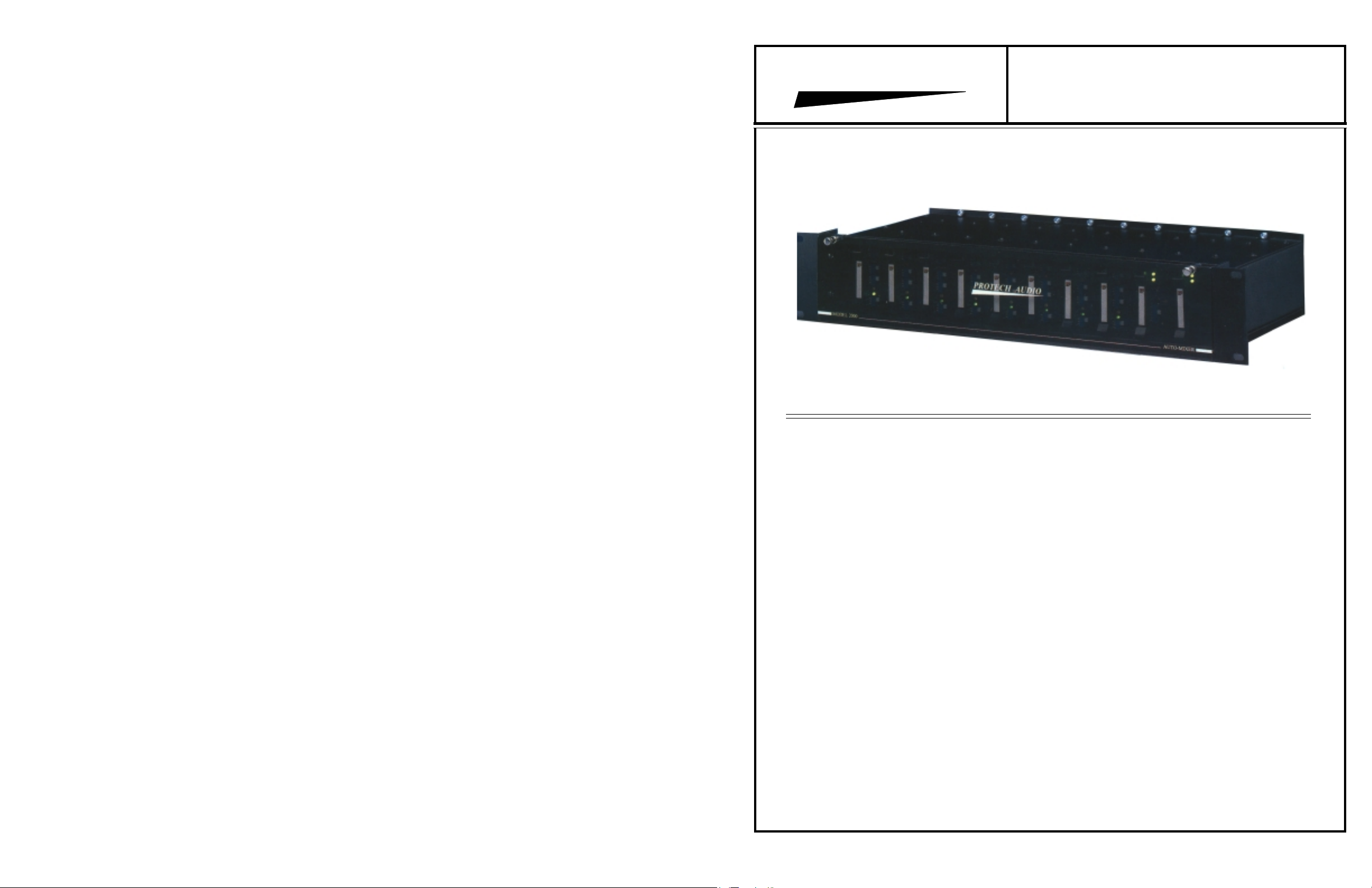
MODEL 2000
WITH MIX-MINUS OUTPUTS.
The Protech Audio Model 2000 Automatic Microphone
Mixer is designed to be the best operating, most transparent
auto-mixer, for fixed installations. From the Dugan Speech
System for transparent gain-sharing, to the mix-minus
output on each input channel, to the card frame mechanical
packaging, the Model 2000 is constructed to provide the
designer and installer with every feature needed for perfect
auto-mixer installations.
Before proceeding further, please make note that the
Model 2000 is shipped from the factory with all preliminary adjustments made. The gain on each input channel
is set to 50dB, the tone controls on each are set to flat,
and the master output level is set to unity. The unit
should be installed, turned on and listened to, before
any additional adjustments are made. In many installations, no further adjustments will be required.
The first feature to make note of is the patented Dugan
Speech System for proper gain sharing in automatic mixing
applications. This operating system, when properly implemented, results in the best, most transparent automatic
mixing to be found anywhere. A short listening demonstration has impressed even the most critical audio system
designers. We at Protech Audio have worked directly with
Dan Dugan Sound Design, for almost 3 years, to achieve
the optimum implementation of his superior auto-mixing
architecture.
The second feature to be discussed is the mix-minus
output on each input channel. Other systems require any
number of additional pieces of equipment, like wiring
matrixes, to achieve mix-minus. In the Model 2000, the
mix-minus feature is inherent in the design. Up to 8 separate
mix-minus outputs are inherent in each card frame assembly.
In addition to the mix-minus output, each input section
incorporates a number of features, to allow installations
to be done quickly, with a minimum of wiring and set-up
time. High-Pass filters, Bass and Treble Controls, Logic
Outputs, Phantom Power, and Mute functions are built
into each input channel.
The output card has provision for two balanced line
outputs, Auxillary Input, switch selectable Master/Slave
operation, Gain Trim, Remote Volume Control, Group
Mute, optional Automatic Level Control, and optional
Pink Noise Generator
The optional Automatic Level Control works in a very
unique manner. Instead of adjusting levels at the output
only, the ALC reaches back into each input channel and
readjusts the gain at each input. This feature allows the mixminus to remain properly adjusted.
The card frame assemblies are linkable, to create systems
with up to 100 microphone inputs. The linking is accomplished by using standard DB15 cables.
Protech Audio Corp., 192 Cedar River Road, Indian Lake New York, 12842 Voice 518-648-6410 Fax 518-648-6395
Page 2

INDEX
Page 2 Page 3 Page 4 Page 6 Page 7 Page 8 Page 9 Page 9 Page 10 Page 11 Page 12 Page 14 Page 16 Page 17 -
Index and Unpacking Instructions.
Unpacking Instructions.
Quickstart Set-Up
Input Card Description.
Input Card Mechanical and Connections.
Output Card Description.
Output Card Mechanical and Connections.
Pink Noise Generator Option
Using Mix-Minus Outputs.
Linking Chassis'
Remote Level Controls
Automatic Level Control Option
Using INTEGRA III SYSTEM Cards With Model 2000
Blank
Also reference application note AN2000.
The Model 2000 Automatic Microphone Mixer
is shipped from the factory with all cards
plugged into their proper slots. The mechanical drawings on the facing page show the
position of individual types of cards. If your
system required less than 8 inputs, the system
is shipped with the higher number card slots
empty. If your systems required more than 8
inputs, additional frames have been shipped,
along with the necessary link cables.
CAUTION: The Model 2000 has been assembled
and aligned at the factory. The unit should be
wired, turned on, and listened to, before any
field adjustments are made.
UNPACKING-
1- Remove chassis assembly from carton.
2- Open card frame front panel by loosening two
thumbscrews, remove pink anti-static shipping
insert and discard.
3- Count input cards, output(s) card, power supply
card(s), link cables, power supply transformers,
to insure correct quantities.
MOUNTING
The Model 2000 Automatic Microphone Mixer is
designed to be mounted in an industry standard
19" EIA rack. Care should be taken not to mount
the unit next to power supplies, power amplifiers,
or other equipment which generate strong AC
fields.
WIRING-
All audio inputs and output(s) should be wired
using double conductor shielded cable. Logic
circuits may be wired using unshielded cable.
- Page 2 -
Page 3
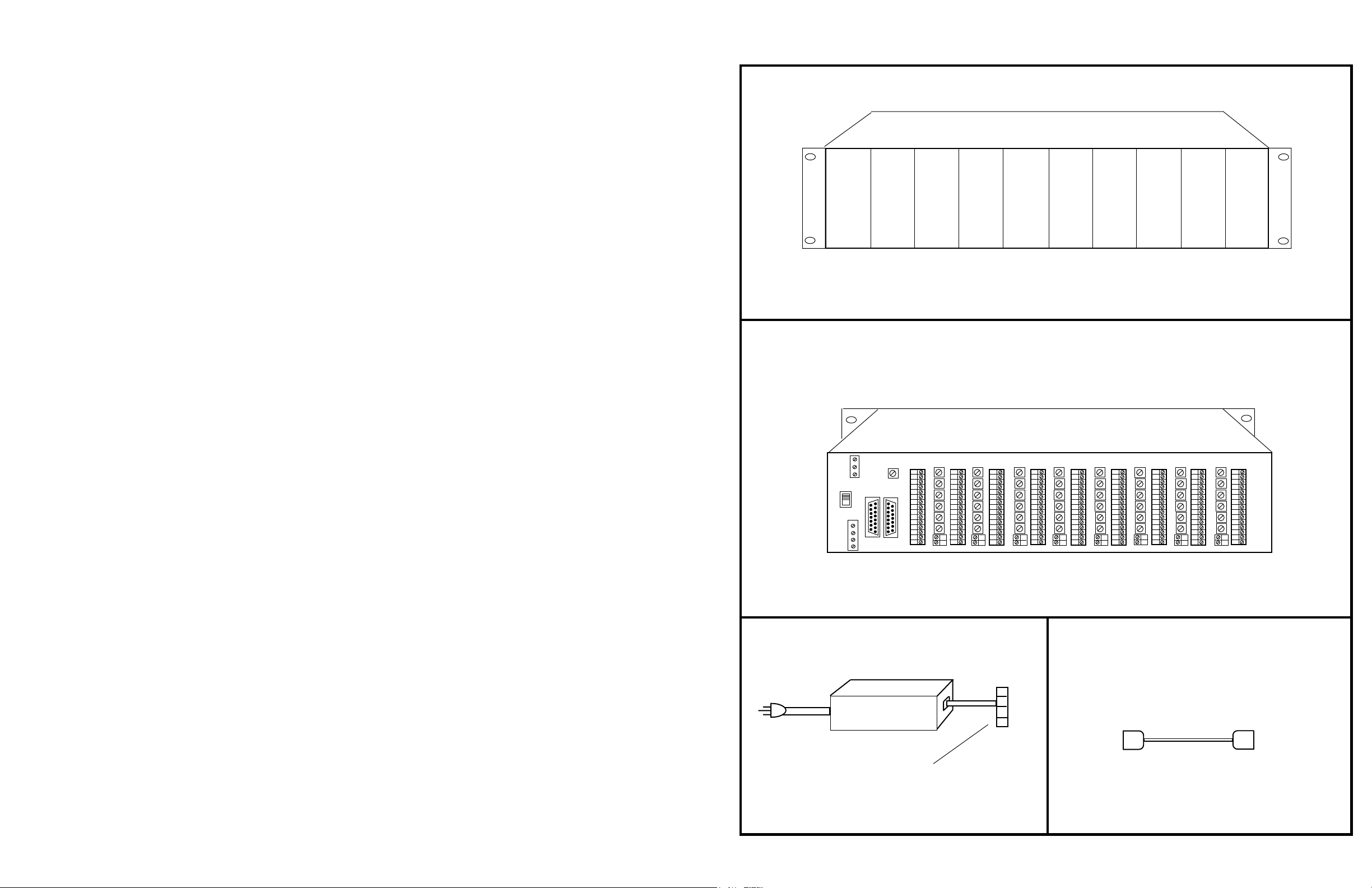
FRONT VIEW
PRODUCT COMPONENTS
INPUT
CARD
SLOT
INPUT
CARD
SLOT
INPUT
CARD
SLOT
INPUT
CARD
SLOT
INPUT
CARD
SLOT
INPUT
CARD
SLOT
INPUT
CARD
SLOT
INPUT
CARD
SLOT
OUTPUT
CARD
SLOT
1 TO 8 INPUT CHANNELS,
SLOTS 1 THRU 8 MAY BE USED FOR OTHER INTEGRA III SYSTEM MODULES
REAR VIEW
+15
GND
-15
GND ON
MASTER
LINK
IN
5678
4
3
2
POWER
SUPPLY
CARD
SLOT
1
18VACT
AC
CT
AC
GND
OUT
POWER SUPPLY, 1 PER
CHASSIS
Connector Plugs Into
Mating Connector On Chassis
(18VACT)
MALE
LINK IN
LINK CABLE
DB15
FEMALE
LINK OUT
- Page 3 -
Page 4

QUICK START SET-UP, STANDARD AUTOMIXER INSTALLS
Unpacking and Mounting -
Unpack each Model 2000 Card Frame Assembly,
loosen thumbscrews and open door. Remove antistatis bubblepack and discard.
Identify which card slots have microphone input
cards, and which have line input cards. (See label on
bottom side of each card, near handle.)
Close door and mount frame in rack. Wire all inputs
and outputs with double conductor shielded cable
(See connection points on pages 7 & 9.)
Inputs - Microphone
Each microphone input card has gain preset at the
factory. If condenser microphones are to be used, set
the gain slide switch to the low position on the
corresponding input card. The microphone input
cards are jumpered for 15 volt phantom power. (See
page 6 for details.)
Inputs - Line
Each line input card has gain preset at the factory for
unity. The line input cards are designed to be used
with devices such as telco echo-cancellers, compact
discs, and tape players. The mode switch on each line
input is factory preset to "Auto". Depending on the
installation, it may be desirable to set it to "Manual".
In manual mode, the automix gain function will not
effect the line input gain.
Tone Controls -
Each input card has a switch selectable high-pass
filter, and Bass and Treble controls. The inputs are
shipped with teh high-pass filter switched out, and
the tone controls set for "Flat".
Output Cards -
The output card has only slide switch, designed to set
the output to Master or Slave operation. If only one
chassis is to be used, no adjustment of the factory
setting, Master, is necessary.
If more than one chassis is to be used, consult page
11.
CAUTION: The Model 2000 has been assembled
and aligned at the factory. The unit should be
wired, turned on, and listened to, before any
field adjustments are made.
Special Features -
The Model 2000 Automatic Mixing system contains
many special features, which allow the unit to perform many special tasks, without the need for additional equipment.
Each special feature and how to use it, is described
in detail, on the following pages. Please see page 2,
for a page index of special features.
UNBALANCED LINE
INPUT
CONNECTION
BALANCED LINE INPUT
CONNECTION
MICROPHONE INPUT
CONNECTION
UNBALANCED LINE OUTPUT
CONNECTION
HI
LO
SH
BALANCED LINE OUTPUT
CONNECTION
HI
LO
SH
HI
LO
SH
HI
LO
SH
- Page 4 -
- Page 17 -
Page 5

USING INTEGRA III CARDS WITH MODEL 2000
QUICK START SET-UP, BLOCK DIAGRAM & CONNECTIONS
The Model 2000-CH chassis will accomodate a
number of different INTEGRA III cards. Each card
has a part number that starts with"2K-", to denote
that it was modified at the factory, to allow operation
in the Model 2000-CH chassis. All other features are
identical. For instance, the Model 665 is a 1 input,
5 output audio distribution amplifier card. The Model
2K-665 is the same card, with a trace modification.
The INTEGRA III cards that are available for use
with the Model 2000-CH chassis are;
2K-662 Audio Distribution Amp, 1 x 2
2K-663 Audio Distribution Amp, 1 x 3
2K-664 Audio Distribution Amp, 1 x 4
2K-665 Audio Distribution Amp, 1 x 5
2K-674 Audio Line Mixer, 2 x 1
2K-675 Audio Line Mixer, 3 x 1
2K-676 Audio Line Mixer, 4 x 1
2K-677 Audio Line Mixer, 5 x 1
NOTES:
INPUT CARD, SLOTS 1 THRU 8
EXTERNAL
+48VDC
REMOTE
GAIN
CONTROL
INPUT
MUTE
INPUT
-1V
+4V
MIX-MINUS
INPUTS
+
-
LOGIC
OUT
INPUT
MUTE
15VDC
Mic/Line
Switch
30/50dB
MASTER OUTPUT CARD, SLOT 9
GAIN
BACK PANEL
GAIN TRIM
HI-PASS
FILTER
MUTE BUSSES
GROUP / ALL
BACK PANEL
TREBLE
BASS
EQVCA 1
GROUP MUTE
SWITCH
Mute
CONTROL
MIX
MASTER
GAIN
VCA 2
AUTO-MIX
CONTROL
MAIN
MIX
Not On
Logging
Slots
MAIN-MIX OUTPUTS
LOG/
MIX
MINUS
PRE MIX
OUT
POST MIX
OUT
DIRECT
IN
LOGIC
OUT
GAIN
INDICATOR
OUT
+
+
-
2K-588 Noise Gate Ducker, 2 x 1
2K-639 Line Amp/Compressor
Other modified INTEGRA III cards are available
upon request.
The trimpot controls, and the 2 pin connector, on the
rear of the Model 2000-CH, will not be functional
when modified INTEGRA III cards are placed into
that card slot. Only the 15 pin connector will remain
functional, to allow termination of the inputs and
outputs.
An extender card, Model 516, may be required, to
allow adjustment of the gain on modified INTEGRA
III cards.
1
2
3
4
5
6
7
8
9
10
11
12
13
14
15
GROUP MUTE
ALL MUTE
MASTER
REMOTE
CONTROL
-1V
+4V
AUX IN
BACK PANEL
MASTER
GAIN TRIM
OPTIONAL
AUTOMATIC
LEVEL
CONTROL
Input Connections Output Connections
Remote Control Voltage for Remote Gain Control.
Input Mute, Grounding Pin Mutes Channel Input.
Ground.
Input Hi.
Input Lo.
48V Phantom From External Source.
Pre Mix Out, after Remote Volume, Mute, & Tone Controls.
Ground
Direct MIx Minus Input (Resistor Isolate)
Gain Ind. Out
Logic Out, Open collector grounded when active.
Post Mix Out, Used for Mix-Minus or Console Insert.
Ground
Mix-Minus Out Hi
Mix-Minus Out Lo
1
2
3
4
5
6
7
8
9
10
11
12
13
14
15
Remote Master In.
All Mute
Ground.
Group Mute.
Pink Noise Option Activation
Do Not Use!
Aux Input Hi
Aux Input Lo (Ground)
Do Not Use!
Do Not Use!
Mix 1 Out Hi.
Mix 1 Out Lo.
Ground.
Mix 2 Out Hi.
Mix 2 Out Lo.
PINK NOISE
GENERATOR
-
+
-
EXT. SW.
- Page 16 -
- Page 5 -
Page 6

AUDIO INPUTS
GAIN -
Each input card has individually adjustable gain.
The gain is preset at the factory. Before any field
adjustments are made to the Model 2000, it is strongly
recommended that the unit be installed, wired,
turned on and listened to. If additional gain adjustments are necessary, they may be made in one
of two ways. (NOTE: If ALC option is used,
switch ALC to "OFF" position, before adjusting
gain trimpots.)
First, there is a gain setting slide switch on the input
card assembly. This switch allows the preamplifier
gain to be set to either 30dB or 50dB. This switch is
set to 50dB at the factory. Most applications will
require the 50dB setting. The 30dB setting is
recommended for condenser type microphones.
Second, each input card slot has a VCA 1 gain
adjustment trimpot mounted on the backplane assembly. The trimpot is set at the factory for -6dB. The
gain settings correspond to "clock" positions with
12:00 being straight up. Additional settings are as
follows:
7:00 =
8:00 =
9:00 =
10:00 =
11:00 =
12:00 =
1:00 =
2:00 =
3:00 =
4:00 =
5:00 =
HIGH PASS FILTER & TONE CONTROLS -
Each input card has a slide switch selectable highpass filter. Each input card slot has individual Treble
and Bass controls. The Model 2000 is shipped from
the factory with the high-pass filter in the "IN"
position. The BASS and TREBLE tone controls are
set to the "FLAT" position. Counterclockwise rotation "CUTS" frequencies, while clockwise rotation
"BOOSTS" frequencies.
The corner frequency of the BASS control is 315Hz,
with a peak at 50Hz. The corner frequency of the
TREBLE control is 1150Hz, with a peak at 10KHz.
-35dB
-33dB
-27dB
-20dB
-15dB
-6dB
0dB - Recommended
+6dB
+11dB
+17dB
+18dB
WEIGHTING CONTROL -
Each input card slot has a "WEIGHTING" control
trimpot. The Model 2000 is shipped from the factory
with the "WEIGHTING" control in the maximum
clockwise position. Most applications will require
this setting.
The "WEIGHTING" control is the send for the automixing "pre-mix". Weighting reduction can be used
when it becomes necessary to balance the automatic
mixing action separately from the audio mix. One
situation would be where one microphone is near an
air vent, and the noise of the air vent makes the gain
go to that microphone when no one is talking. The
weight for that channel can be backed off so the automix gains balance. The ambient weighting can be
skewed up to 10dB without affecting the mixing of
the voice signals. The weight is normally left at
maximum position (full clockwise) for maximum
dynamic range in the auto mixing system.
PHANTOM POWER -
Each input card has a 3 pin terminal strip to allow
jumpering for phantom power. A red push-on jumper
is supplied for each input card. By placing the jumper
on the #2 and #3 terminals, the card will supply
15VDC phantom power to the microphone. By placing the jumper on the #1 and #2 terminals, the card
will allow 48 volt phantom power to be supplied
from an external source. Each input card is individually configured. The unit is shipped with the jumper
in the external 48 volt position.
MUTE, INPUT MUTE & GROUP MUTE -
Each input card has a MUTE slide switch, used for
troubleshooting.
Each input card has a separate mute pin. Grounding
this pin will mute the input.
Each input card has a slide switch that enables the
card to be attached to a group mute function. Grounding the Group Mute pin on the Master card slot will
mute all inputs attached to the Group Mute function.
The input cards are shipped with the GROUP MUTE
enabled.
AUTOMATIC/MANUAL OPERATION
Each input card has a slide switch that allows the
individual card to operate automatically, or manually .
NOTES:
ALC FEATURES
AUTOMATIC LEVEL CONTROL (ALC) CARD ASSEMBLY
(Mounted on Master Output Card Assembly)
A
B
MASTER
C
ON
D
EXTERN.
ABCDEFG-
OFF
ALC Active.......................
(Level Gate)......................
ALC Gain Indicator...........
ALC ON-OFF Switch........
RATE Trimpot..................
TARGET Trimpot.............
WINDOW Trimpot............
RATE
E
Indicates active ALC function
N/A
Displays gain reduction.
Used for set-up
Controls speed of ALC action.
Controls desired output level.
Controls "dead zone" for dynamic range function.
TARGET
WINDOW
F
G
MIX-MINUS - see page 12 mix-minus section.
- Page 6 -
- Page 15 -
Page 7

AUTOMATIC LEVEL CONTROL OPTION
NOTE 1:
Always turn the ALC assembly off (switch down)
when adjusting
any system gain controls, including mixer inputs, master gain control, tone controls, system equalizers, and amplifiers.
If this procedure is not followed, the ALC may
fade the gain back up when someone speaks
softly, and the system may go into feedback.
NOTE :
The automatic level control card assembly has
been aligned at the factory. Normally, no further
adjustments are necessary.
How It Works.
The ALC's function is to fade the master gain
down when the speaker is too loud, and hold it
there during pauses. When a quieter speaker talks,
the gain will be raised again. The ALC compares
the level of the mixer's output, measured with a
VU meter characteristic, with a threshold set by
the TARGET trimpot control. When the output
level is lower than the threshold, the ALC will
fade up the master gain. When the output level is
higher than the threshold, the ALC will fade the
master gain down. The speed of the fade is set
with the RATE trimpot control.
The gating action of the ALC freezes the master
gain when no one is talking. Normally it is controlled by the logic outputs of the automatic
mixing input channels. Whenever a yellow logic
LED on any channel is on, the ALC action is
allowed to adjust the output level. The yellow
ALC ENABLE LED will come on when any
input's logic LED is on, and indicates when the
ALC is active.
Factory Settings- Recommended positions.
RATE Trimpot = 12:00, Counterclockwise =
Slower
TARGET Trimpot = 9:00, Counterclockwise =
Downward
WINDOW Trimpot = 12:00, Counterclockwise =
More Dynamic range
ALIGNMENT PROCEDUREUnplug the power supply card. Unplug and remove
the master output card assembly (with ALC card
assembly). Plug the extender card into the master
output card slot. Plug the master output card assembly into the extender card. Plug in the power supply
card
With the ALC switched to "OFF", adjust all input
gains, master output gains, tone controls, and adjacent channel input controls, as well as any other
equipment in the signal chain (equalizers, power
amps, etc.). Be sure to test with speech at all microphones after any gain adjustment. Because of the
automatic mixing action, a microphone that may be
ready to feed back, will not have it's gain turned up
until someone speaks into it.
Turn the ALC "ON". Have someone speak loudly at
a microphone. Adjust the TARGET trimpot downward (counterclockwise) until the volume is reduced
to a comfortable level. The middle green LED is
illuminated to indicate where the target level should
be. Now the ALC will fade the master gain down
whenever the output level is higher than the TARGET level. When a quieter speaker talks, the gain
will fade up again.
Next adjust the RATE trimpot to 12:00 or lower.
This will increase the ALC fade time so that it
doesn't "pump". 100% counterclockwise is the
slowest setting.
If more dynamic range is desired, more difference
between loud and soft speakers, turn the window
control counterclockwise. This will create a "dead
zone" below the threshold level, where the volume
can vary naturally without ALC action. A WINDOW
setting of 50% gives a dead zone of 5dB, and 0%
(full counterclockwise), about 8dB.
Exempting Line Level Inputs From ALCSince the ALC works by varying the master gain
when a logic indicator is active, removing R23
prevents the ALC from changing the gain on the line
input, whenever any input becomes active.
INPUT FEATURES
INPUT CARD ASSEMBLY
GROUP MUTE
DISABLE
ENABLE
RED
NORMAL
MUTE
YELLOW
GREEN
AUTO
MANUAL
A =
Switch allows individual channels to be connected to Group Mute. (Shipped "Enabled")
B =
Switch allows individual channels to be muted for troubleshooting. (Shipped "Normal")
C =
Switch allows either automatic or manual operation of individual input channels.(Shipped "Auto")
D =
High-Pass filter (Rumble). (Shipped "Out")
E =
HI-LO gain switch, 50 or 30 dB, for use with different microphone types. (Shipped "HI")
F =
Placing RED push-on shunt on pins +48 and middle, allows external 48 volt phantom to be used.
(Shipped "15V")
G =
Mic/Line switch, for determining input impedance and gain structure. (Shipped as MIC input)
H =
Factory set, to allow mix-minus output
I =
Placing RED push-on jumper determines whether pre-mix outputs are pre or post mute.
LED's =
Gain Set
Bass Control
Treble Control
Adjacent Channel Mix-Minus L
Adjacent Channel Mix-Minus R
Adjacent Channel In
Adjacent Channel In
A
ALL ADJUSTMENTS ON
B
C
Red indicates Mute Function.
Yellow indicates Logic function.
Green indicates gain function.
DAUGHTER BOARD ARE
MADE AT FACTORY.
DO NOT READJUST ANY
TRIMPOTS ON DAUGHTER
BOARD
TYPICAL INPUT CONNECTION, 1 OF 8
10
11
12
13
14
15
G
Line---Mic
F
E
HI LO
GAIN
1
2
3
4
5
6
7
8
9
Remote Control Voltage
Input Mute,
Ground.
Input Hi.
Input Lo.
48V Phantom From External Source.
Pre Mix Out
Ground
Direct MIx Minus Input (Resistor Isolate)
Gain Ind. Out
Logic Out
Post Mix Out, Used for Mix-Minus or Console Insert.
Ground
Mix-Minus Out Hi
Mix-Minus Out Lo
I
PRE
MUTE
POST
IN
PHANTOM
+15 +48
H
D
HP
OUT
LOG
M/M
- Page 14 -
- Page 7 -
Page 8

OUTPUT SET-UP
REMOTE VOLUME CONTROL OPTIONS
GAIN -
Each output card slot has a Master VCA 2 gain
adjustment trimpot mounted on the backplane assembly. The master gain trimpot adjusts all VCA 2's
together. The trimpot is set at the factory for -6dB.
The gain settings correspond to "clock" positions
with 12:00 being straight up. Additional settings are
as follows:
7:00 =
8:00 =
9:00 =
10:00 =
11:00 =
12:00 =
1:00 =
2:00 =
3:00 =
4:00 =
5:00 =
AUXILLARY INPUT -
The Auxillary Input is an unbalanced input, designed
to allow insertion of audio signals from devices such
as cassette players, computers, tape machines, and
CD players.
-33dB
-33dB
-27dB
-23dB
-18dB
-13dB
-10dB
-5dB
0dB
+4.5dB
+5dB
Recommended
MASTER/SLAVE OPERATION-
Each output card has a slide switch, which determines whether the frame assembly is used as a
master or slave. The slave position is used only when
two or more frames are linked together.
In the "MASTER" position, the frame controls the
auto-mixing function for the cards within the frame,
and any frames, to which it may be linked.
In the "SLAVE" position the frame allows control of
the auto-mixing function from an external "MASTER" frame. All of the input card signals in the
"SLAVE" frame will appear on the outputs of the
"MASTER" frame.
The "SLAVE" frame main outputs will contain
only the input signals originating within the frame.
PINK NOISE GENERATOR OPTION -
The pink noise generator option provides a pink
noise signal, that is activated by a ground closure,
that appears on the main output, and all mix-minus
outputs. This feature is designed to provide privacy,
in courtroom applications.
MODELS 2000-RVC-IN & 2000-RVC-OP
REMOTE VOLUME CONTROLS
FRONT VIEW
REAR VIEW
Single-Gang Wall Plate
- Page 8 -
- Page 13 -
Page 9

REMOTE VOLUME CONTROL CONNECTIONS
OUTPUT FEATURES
Note: Models 2000-RVC-IN (Input Remote Control) & 2000-RVC-OP (Output Remote Control) are available to provide the remote control circuits described below.
See next page.
Wire one resistor-potentiometer circuit for each output circuit requiring remote
1-
level control.
Turn gain trimpots on chassis full counterclockwise, on all channels having
2-
remote level.control circuits
Set all remote potentiometers to full clockwise position.
3-
Apply AC power to external power transformer.
4-
Adjust each input and output trimpot to required level by rotating trimpots
5-
clockwise. Suggested settings are 1:00 for input gain trimpots, and 12:00
for the master output trimpot.
This alignment procedure will allow the installer to limit the
maximum gain available to the end user.
A =
LED's =
OUTPUT CARD ASSEMBLY
SPACE RESERVED FOR
OPTIONAL ADD-ON
MASTER
AUTOMATIC LEVEL CONTROL
PC ASSEMBLY.
SLAVE.
Switch allows chassis to be linked, as master or slave unit.
Green indicates +DC power.
TYPICAL OUTPUT CONNECTOR
+15
GND
-15
GND ON
18VACT
AC
CT
AC
GND
MASTER
LINK
IN
OUT
Output
12K
10K Pot
2K
Model 2000-RVC-OP
Circuit
To Pin 1 On
Ouput card
connector
678
- Page 12 -
+15
-15
5
4
3
Input
6.8K
10K Pot
18K
Model 2000-RVC-IN
Circuit
Master Gain Set
2
1
1
2
3
4
5
6
7
8
9
10
11
12
13
14
15
Remote Master In.
All Mute
Ground.
Group Mute.
Pink Noise Option Activation
Do Not Use!
Aux Input Hi
Aux Input Lo (Ground)
Do Not Use!
Do Not Use!
Mix 1 Out Hi.
Mix 1 Out Lo.
Ground.
Mix 2 Out Hi.
Mix 2 Out Lo.
OUTPUT CONNECTOR FUNCTIONS
1 -
To Pin 1 On
Input card
connector
Remote Master In..............
2 -
All Mute............................
3 -
Ground...............................
4 -
Group Mute.......................
5 -
Spare..................................
6 -
N/A.....................................
7 -
AUX In HI.........................
8 -
Ground................................
9 -
N/A....................................
10 -
N/A....................................
11 -
Mix Out Hi.........................
12 -
Mix Out Lo........................
13 -
Ground...............................
14 -
Mix Out Hi.........................
15 -
Mix Out Lo........................
External DC voltage to control master output level.
Grounding pin mutes all inputs.
Ground.
Grounding pin mutes all inputs with group mute switch in "ENABLE" position.
Not Used
Do Not Use!
Auxillary Input High
Auxillary Input Low
Ground
Do Not Use!
Main Mix #1 Output High.
Main Mix #1 Output Low.
Ground.
Main Mix #2 Output High.
Main Mix #2 Output Low.
- Page 9 -
Page 10

USING MIX-MINUS OUTPUTS
MULTI-CHASSIS LINKING CONNECTIONS
Each input channel has a discrete mix-minus output.
The mix-minus output on each input card has all
input signals received on the mixing buss except the
signal received on that input (primary signal).
In addition to the primary signal being removed
on the mix-minus output, each input card has
several provisions for additional signals to be
removed or attenuated on the mix-minus output.
Two signals are referred to as adjacent channel
left, and adjacent channel right. This description is
intended to describe microphones located next
to each other in a room, not card slot locations
in the card frame. Additional signals may be
removed using the direct input, or the
Model 704 Modular Matrix Mixer cards.
CONNECTION AND CONTROL DRAWING
Gain Set
Bass Control
Weighting
Treble Control
Adjacent Channel Mix-Minus L
Adjacent Channel Mix-Minus R
Adjacent Channel In L
Adjacent Channel In R
1
2
3
4
5
6
7
8
9
10
11
12
13
14
15
The drawing at the bottom of this page shows the
wiring connections needed to use the mix-minus
output, with adjacent channels left and right. (Note:
Depending on microphone to speaker spacing, it is
not always necessary to attenuate adjacent channels.) The adjacent channels have trimpot controls
that allow the amount of signal attenuation to be
adjusted. As shown below, the channel two mixminus output would have input two removed, and
inputs 1 and 3 attenuated to whatever level the
adjacent channel trimpots are set. The direct input
allows other signals to be removed, should that
become necessary. This wiring scheme would be
duplicated wherever adjacent channels need attenuation.
Remote Control Voltage for Remote Gain Control.
Input Mute, Grounding Pin Mutes Channel Input.
Ground.
Input Hi.
Input Lo.
48V Phantom From External Source.
Pre Mix Out, after Remote Volume, Mute, & Tone Controls.
Ground
Direct Mix-Minus Input (Resistor Isolate)
Gain Ind. Out
Logic Out, Open collector grounded when active.
Post Mix Out, Used for Mix-Minus or Console Insert.
Ground
Mix-Minus Out Hi
Mix-Minus Out Lo
On master chassis, set master/slave switch (see output section for location) to
1-
master.
On slave chassis(s), set master/slave switch to slave.
2-
Use 2000-CA link cable to connect chassis(s).
3-
Use Master trimpot on master chassis to adjust all input levels simultaneously.
4-
Note: If ALC option is used, the ALC is placed on the output board of the
master chassis.
MASTER CHASSIS
+15
GND
-15
GND ON
18VACT
AC
CT
AC
GND
MASTER
LINK
IN
OUT
678
5
4
3
2
1
TYPICAL INPUT CONNECTION, 1 OF 8
INPUT 3 INPUT 1
1
2
3
4
5
6
7
8
Direct In
9
10
11
12
13
14
15
INPUT 2
1
2
3
4
5
6
7
8
9
10
11
12
13
14
15
- Page 10 -
Direct In
TO
POWER AMP
1
2
3
4
5
6
7
8
9
10
11
12
13
14
15
Direct In
+15
GND
-15
GND ON
18VACT
AC
CT
AC
GND
MASTER
LINK
IN
OUT
FROM ADDITIONAL CHASSIS
SLAVE CHASSIS
678
- Page 11 -
5
4
23
1
 Loading...