

Page 1
Protec Fire Detection plc, Protec House, Churchill Way, Nelson, Lancashire, BB9 6RT, ENGLAND
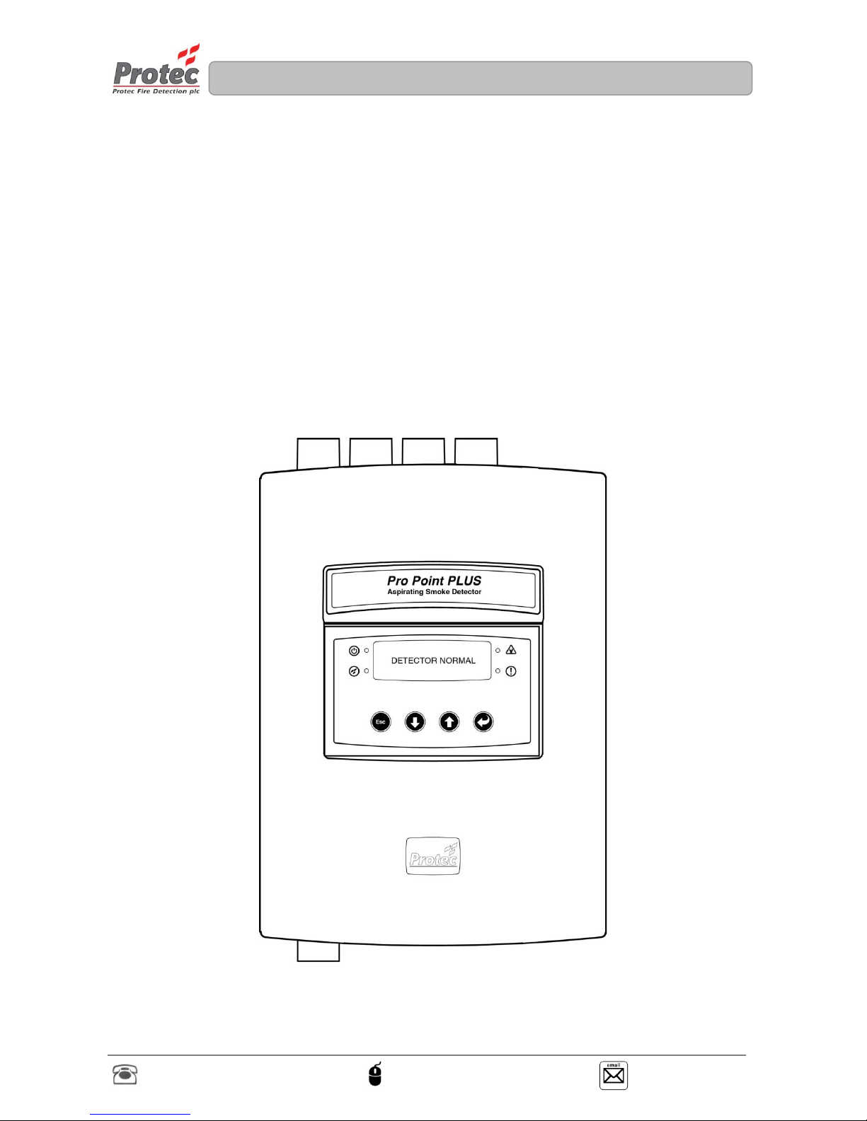
PROPOINT PLUS ASPIRATING
SMOKE DETECTION SYSTEM
USER MANUAL
Page 2

N 93-602-00 Issue 1 Page 2 of 10 © Protec Fire Detection PLC 2015
Document Revision Details
Issue
Modification Detail
Author
Date
01
Document Creation
RB
15/11/2015
Page 3
N 93-602-00 Issue 1 Page 3 of 10 © Protec Fire Detection PLC 2015
Table of Contents
1.0 SCOPE OF DOCUMENT ....................................................................................................................... 4
1.0 USER RESPONSIBILITIES ................................................................................................................... 4
2.0 INTRODUCTION .................................................................................................................................... 4
3.0 PROPOINTPLUS – GENERAL OVERVIEW ......................................................................................... 5
3.1 DISPLAY ................................................................................................................................................ 5
3.1 FAULT ................................................................................................................................................... 6
3.2 PRE-ALARM ........................................................................................................................................... 7
3.3 FIRE ..................................................................................................................................................... 8
4.0 FAULTS .................................................................................................................................................. 9
5.0 TECHNICAL SPECIFICATIONS .......................................................................................................... 10
There are no user serviceable parts inside the ProPointPlus. A competent person trained to
undertake such work MUST carry out any internal maintenance work. A separate installation
and commissioning manual is available.
This equipment has been manufactured in conformance with the requirements of all
applicable EU council directives and regulations.
Electrical or electronic devices that are no longer serviceable must be collected separately and
sent for environmentally compatible recycling (in accordance with the European Waste
Electrical and Electronic Equipment Directive). To dispose of old electrical or electronic devices,
you should use the return and collection systems put in place in the country concerned.
The policy of Protec Fire Detection plc is one of continuous improvement. As such we reserve the right to
make changes to product specifications at any time and without prior notice. Errors and omissions excepted.
Page 4

N 93-602-00 Issue 1 Page 4 of 10 © Protec Fire Detection PLC 2015
1.0 Scope of document
This document details the user information for the Protec ProPointPlus Aspirating Smoke Detector with
specific attention to the basic system operations of the product. The Protec ProPointPlus Aspirating Smoke
Detector has been designed and manufactured in the United Kingdom and complies fully with current
standard dictating aspirating smoke detector design practice (EN54 parts 20).
2.0 User Responsibilities
The registered owner of the fire alarm system has specific responsibilities regarding the installation, testing
and maintenance of the fire alarm system.
BS5839 Pt 1: 2013 Section 7 states that the user of the fire alarm system must appoint a single named
person to supervise all matters regarding the fire alarm system.
Summarised below are the responsibilities expected of the named person,
It is strongly advised that a full copy of BS5839 Pt 1: 2013 is obtained and
thoroughly read and understood.
3.0 Introduction
Aspirating detection is now a recognised solution for many different fire detection applications. ProPointPlus
provides up to four separate detectors within a common aspirator enclosure and therefore provides four
individually identifiable areas of detection per aspirator.
Each of the four plug in Scatter Camber Detectors (SCD’s) detector use independent and integrated alarm
decision making. Complex algorithms are used to extend the range of particle detection, confirm genuine
alarms and reduce unwanted alarms.
Installation, configuration and commissioning of the ProPointPlus detectors is very simple and installer
friendly. Configuration to either Class A, Class B or Class C sensitivity options is achieved through a multifunction OLED display without the need for a PC connection.
The features of the ProPointPlus are:
High performance optical detection with
optional enhanced CO detection.
1 to 4 individual detectors.
Protec 6000 series digital addressable
protocol.
Simple sensitivity configuration setup:
Class A, Class B, Class C and Prison.
On-board loop isolator.
Common Fault output contact.
5 Programmable output contacts.
3 Programmable input contacts.
Airflow monitoring per pipe.
Variable blower speed control.
Integral OLED display for fault reporting and
ease of setup.
Commissioning menu access code protected.
Support multiple language menu functions.
TCP/IP Network configurable.
Page 5
N 93-602-00 Issue 1 Page 5 of 10 © Protec Fire Detection PLC 2015
4.0 ProPointPlus – General Overview
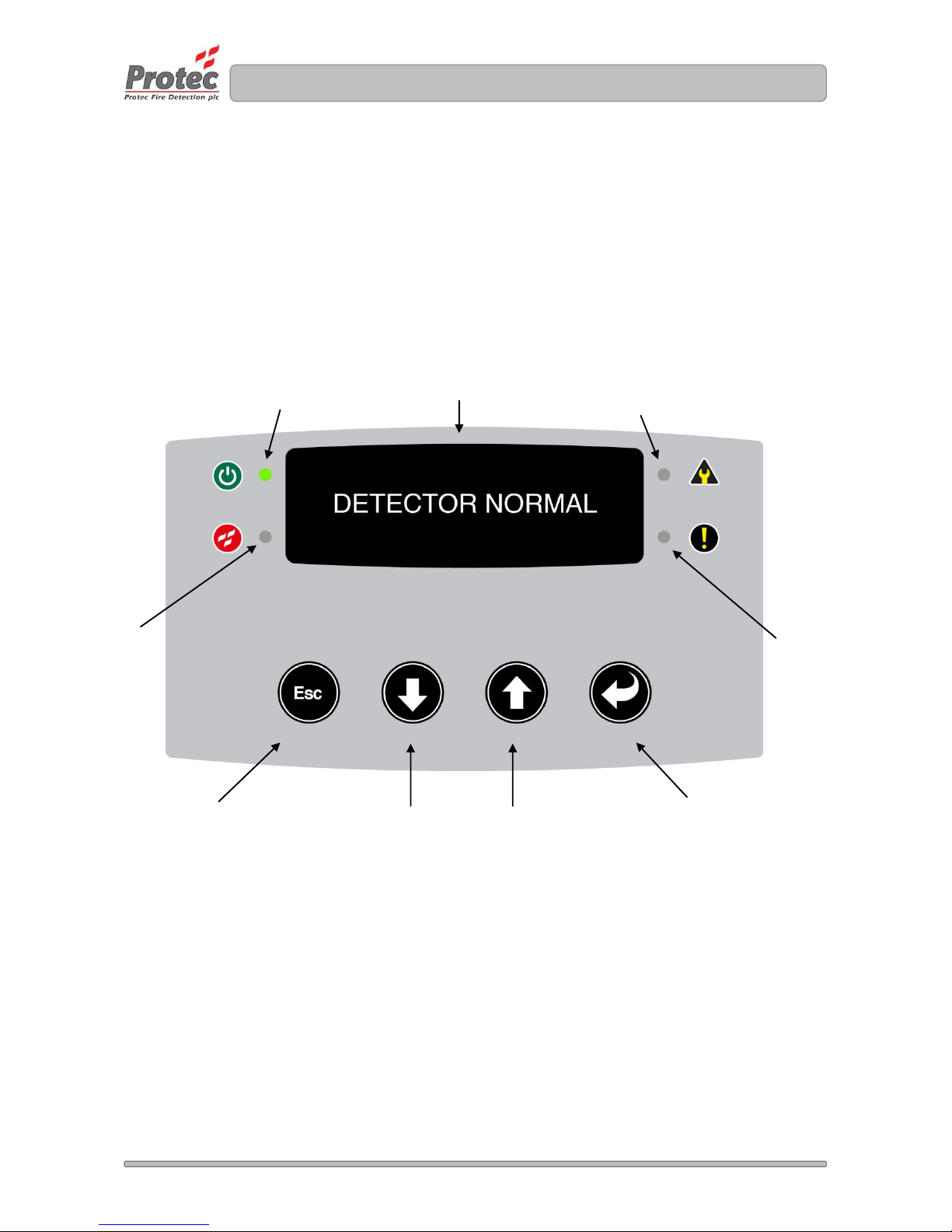
The ProPointPlus detector is capable of displaying all faults and fire events on the OLED screen. The
detector is fitted with an internal buzzer. The buzzer will sound distinctive pulse tones when the unit is in
Fault, Pre-alarm or Fire (providing the buzzer is enabled at commissioning). The buzzer can be muted by
pressing any button. LED indicators are programmed to illuminate corresponding to a specific event.
The button functions are to navigate thought the commissioning menu and are therefore not a requirement
for the user.
4.1 Display
Figure 4.1 ProPointPlus display detector normal
Power LED (Green)
Fire LED
(Red)
Pre Alarm
LED (Amber)
Fault LED (Amber)
Escape / Back
Decrement
Increment
Enter / Accept
OLED Display
Page 6
N 93-602-00 Issue 1 Page 6 of 10 © Protec Fire Detection PLC 2015
4.2 Fault
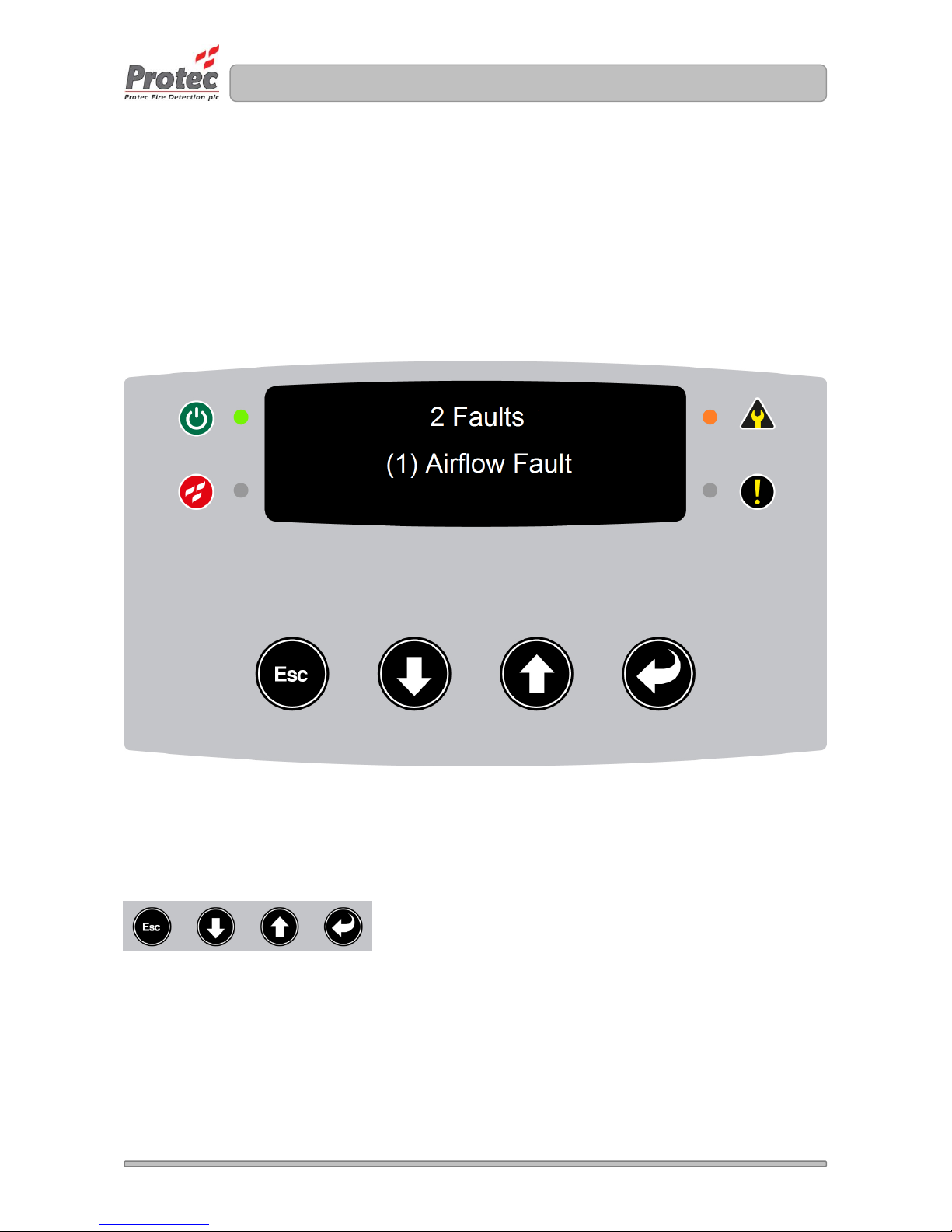
The ProPointPlus displays all faults on the OLED display. Providing no pre-alarms or fires are active the
text ‘Fault’ or ‘Faults’ will be displayed; including the number of faults indicated in front of the text. A brief
description of the device fault is displayed in the centre of the display. When more than one faults is
reported; the faults are automatically scrolled though each fault on the display. The fault LED will be
illuminated.
If the fault is pipe specific; the pipe number is displayed in brackets next to the fault for example below
shows ‘(1) Airflow Fault’ describes an airflow fault on pipe 1.
Figure 4.2 ProPointPlus displaying a fault condition
Refer to section 4.1 which lists all fault including a description and action.
Muting the buzzer
The buzzer can be muted by pressing any button.
Page 7
N 93-602-00 Issue 1 Page 7 of 10 © Protec Fire Detection PLC 2015
4.3 Pre-alarm
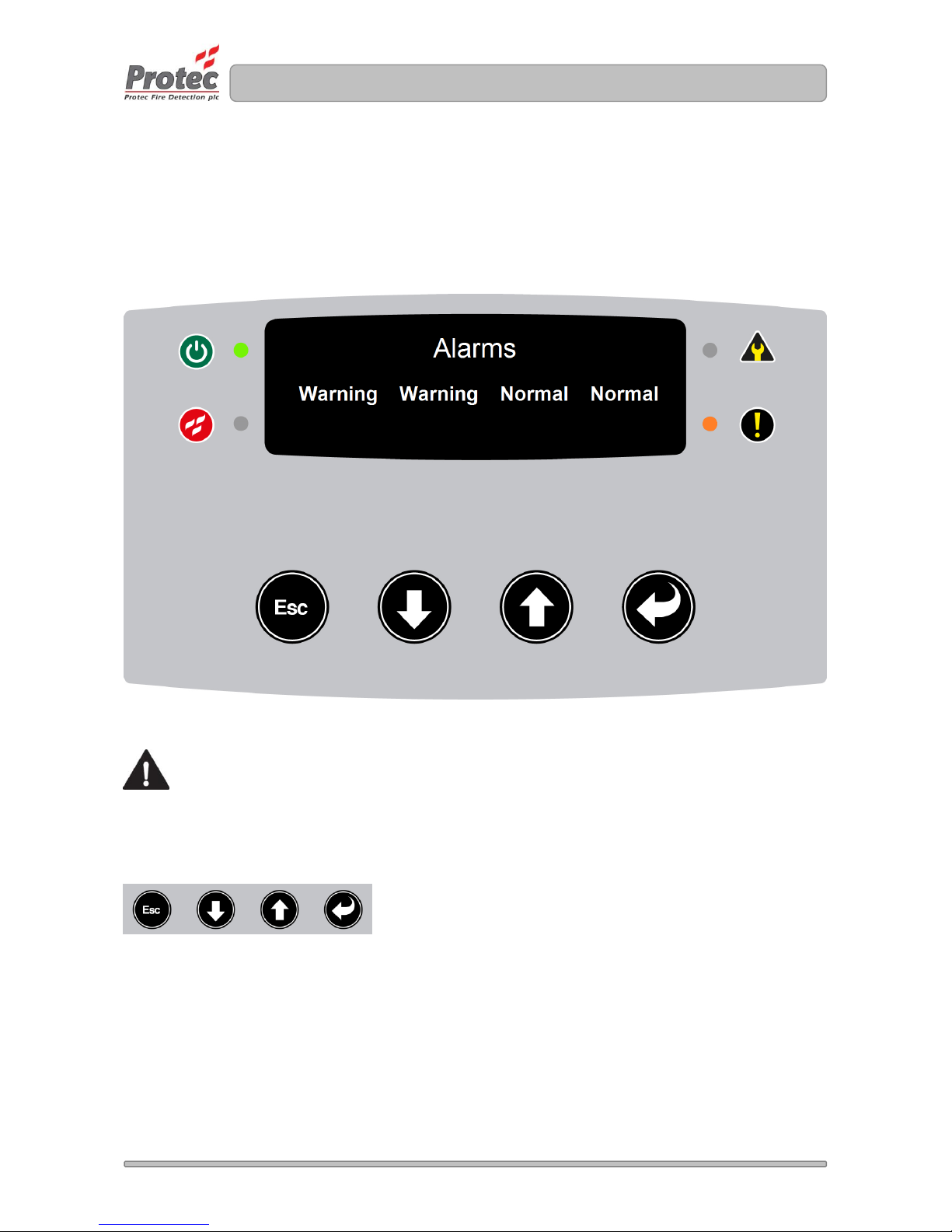
The Pre-alarm condition takes priority over faults. When a pre-alarm condition is activated the display
shows all pipes commissioned (1, 2, 3 or 4). The Pre-alarm text is represented as ‘Warning’. The figure 3.2
below shows 4 pipes; where Pipe 1 and Pipe 2 are in Pre-Alarm condition: ‘Warning’, Pipe 3 and Pipe 4 are
in ‘Normal’ condition. The Pre-Alarm LED is illuminated, any commissioned outputs will activate and the fire
condition is reported to the Protec Fire panel.
Figure 4.3 ProPointPlus displaying Pre-Alarm condition
The appointed ‘Responsible Person’ should investigate the relevant area following the official
procedures for the building. Extreme care must be exercised at all times.
Muting the buzzer
The buzzer can be muted by pressing any button.
Page 8
N 93-602-00 Issue 1 Page 8 of 10 © Protec Fire Detection PLC 2015
4.4 Fire
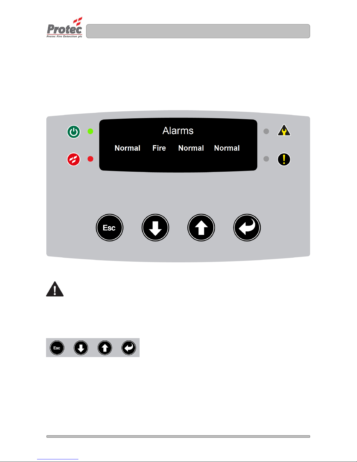
The Fire condition is prioritised over Pre-Alarm and faults. When a fire condition is activated the display
shows all pipes commissioned (1, 2, 3 or 4). The fire text is represented as ‘Fire’. The example picture
below shows 4 pipes; where Pipe 2 are in Fire condition, Pipe 1, Pipe 3 and Pipe 4 are in ‘Normal’
condition. The Fire LED is illuminated, any commissioned outputs will activate and the fire condition is
reported to the Protec Fire panel.
Figure 4.4 ProPointPlus displaying Fire Alarm condition
The building fire plan must be executed immediately.
Muting the buzzer
The buzzer can be muted by pressing any button.
Page 9

N 93-602-00 Issue 1 Page 9 of 10 © Protec Fire Detection PLC 2015
5.0 Faults
The ProPointPlus monitors various aspects of the unit to ensure the unit is fully operational. During faults the
fault LED will illuminate and the buzzer will sound a slow pulse tone. Listed below are the diagnosed faults
indicated on the unit.
Table 1 System Faults
Fault
Description
Action
Device
Missing
A communication problem to a device within the unit
has been detected or a device has been removed
from the unit.
Check the device in fault is fitted
correctly otherwise contact a
Protec operative or a Protec
distributor.
Device
Added
A new device has been added to the unit but the
device has not been commissioned.
Contact a Protec operative or a
Protec distributor.
Airflow Fault
The airflow measurement has moved outside the
acceptable tolerance range either by an increase or
decrease in normalised airflow.
Check sampling pipe installation
is correct as per commissioning,
ensure no pipes are blocked.
If fault persists contact a Protec
operative or a Protec distributor.
Supply Fault
The supply fault monitoring input is reading low.
Typically connected to the external power supply
charger unit.
It may be necessary to look at the
power supply charger unit to
determine the cause of the fault.
If fault persists contact a Protec
operative or a Protec distributor.
High Optical
Background
The optical value has increased outside the normal
operation range.
Contact a Protec operative or a
Protec distributor.
Low
Background
The optical value has decreased outside the normal
operation range.
Contact a Protec operative or a
Protec distributor.
Link Fault
The data (RS485) path has failed.
Contact a Protec operative or a
Protec distributor.
Output
Override
The inputs ‘check to test’ option is active, activated
using the ProView.exe PC software.
Contact a Protec operative or a
Protec distributor.
Corrupt
Settings
Internal settings are outside the expected values.
Unit will default to factory settings.
Contact a Protec operative or a
Protec distributor.
Low Supply
The supply voltage to the unit is below the operating
value (<19VDC).
Contact a Protec operative or a
Protec distributor.
Corrupt File
Web server file is corrupt.
Contact a Protec operative or a
Protec distributor.
Calibration
Fault
The SCD calibration offset value is out of limits.
Contact a Protec operative or a
Protec distributor.
LED Fault
The SCD optical LED is damaged.
Contact a Protec operative or a
Protec distributor.
Airflow
Ignored
A pipe airflow is set to be ignored, activated using the
ProView.exe PC software.
Contact a Protec operative or a
Protec distributor.
CO Cell Fault
The SCD Carbon Monoxide (CO) cell has expired its
life capacity or is missing.
Contact a Protec operative or a
Protec distributor.
Fan Fault
The fan is damage or under/over performing.
Contact a Protec operative or a
Protec distributor.
Isolated Fault
Either the SCD(s) have been individually disabled or
the isolate input is active.
If used check external input
isolation equipment. Otherwise
contact a Protec operative or a
Protec distributor.
Heat Fault
The heat thermistor reading is out of range.
Contact a Protec operative or a
Protec distributor.
Incomplete
Manufacture
The manufacturing details have not been stored in
the unit.
Contact a Protec operative or a
Protec distributor.
Fault (85)
An incorrect SCD device fitted in the unit.
Contact a Protec operative or a
Protec distributor.
Page 10

N 93-602-00 Issue 1 Page 10 of 10 © Protec Fire Detection PLC 2015
6.0 Technical Specifications
Table 2 Technical Specifications
Parameter
Operating Conditions / Limitations
Power Supply
21VDC to 28VDC, Minimum 2ADC: Approved to EN54 Part 4
Power Supply Fuse
1.6A
Voltage Operating Range
21VDC to 28 V
DC
Maximum Current
Consumption
600mADC maximum at 24VDC (blower set to 100%, 4 Pipe Detector)
Loop Protocol
Protec Algo-tec™ 6000
Loop Isolator
On board consult Protec DEL2110 for details
Loop Quiescent Current
Consumption
0.7mA
Fault Contact
Rated at 30 VDC DC 1 ADC maximum [Normally open]
Input Contacts [1 to 3]
3 Programmable monitored inputs 30 V
DC
[Active Low]
Max applied voltage 30 VDC, Open Circuit Voltage ~16 V
DC
Closed Circuit Resistance 1k5Ω
Output Contacts [1 to 5]
5 Programmable Clean Contact Outputs
Rated at 30 VDC, 1 ADC max [Normally open]
Power Supply Input
Monitor
Normal 24VDC Input, Fault ≤ 2.5V
DC
Temperature Range
0°C to 45°C ambient
Humidity Limit
0 - 95% non-condensing ambient
Indicators
Power [Green LED]
Fault [Amber LED]
Pre-Alarm [Amber LED]
Alarm/Fire [Red LED]
OLED Display – Unit status (Faults, Pre-Alarm and Fire), and Commissioning
menu
Sensitivity
A = High
B = Enhanced
C = Normal
Number = sampling hole
alternative to point type smoke
detector
Holes
per
pipe
(max)
Pre-Alarm
Level1*
Fire Level1*
A1, A2, A3
3
150 ≙ 2.2%/m
200 ≙ 2.9%/m
B1, B2 , B3, B4, B5
5
150 ≙ 2.2%/m
250 ≙ 3.6%/m
C1, C2 , C3 , C4, C5, C6, C7, C8
8
150 ≙ 2.2%/m
250 ≙ 3.6%/m
Prison
1
Max area coverage per
pipe
800m2 (C8 setting to British Standards or see local design -codes)
CO area coverage
100m2 (Settings A1, B1, C1 and Prison sensitivity only)
Sensitivity Range
0.12%/m to 11%/m
Sound Pressure Levels
70dB [peak] (Blower at 100%)
Airflow Monitoring
High and Low airflow monitoring
Airflow Monitoring Range
± 5% to 50% respectively. For EN54 Part 20 compliance, Unit tolerance set
to ≤ 20% set by the PC commission tool.
Airflow Velocity Range
0.5 m/s to 6 m/s
Event Log
256 events stored on FIFO basis
Environmental History
Typically 1 Month depending on activity
IP Rating
IP30
Cable Access
10x 20mm replaceable knockouts
Cable Termination
Screw terminal blocks
(0.2 - 2.5 mm2, 30 - 12AWG)
Connectivity
TCP/IP Networking Protocol RJ45 Socket connection
USB type B Socket connection
Pipe OD
25mm
Pipe Length Maximum
200m (To be confirmed by sampling pipe calculation program)
 Loading...