

Page 1
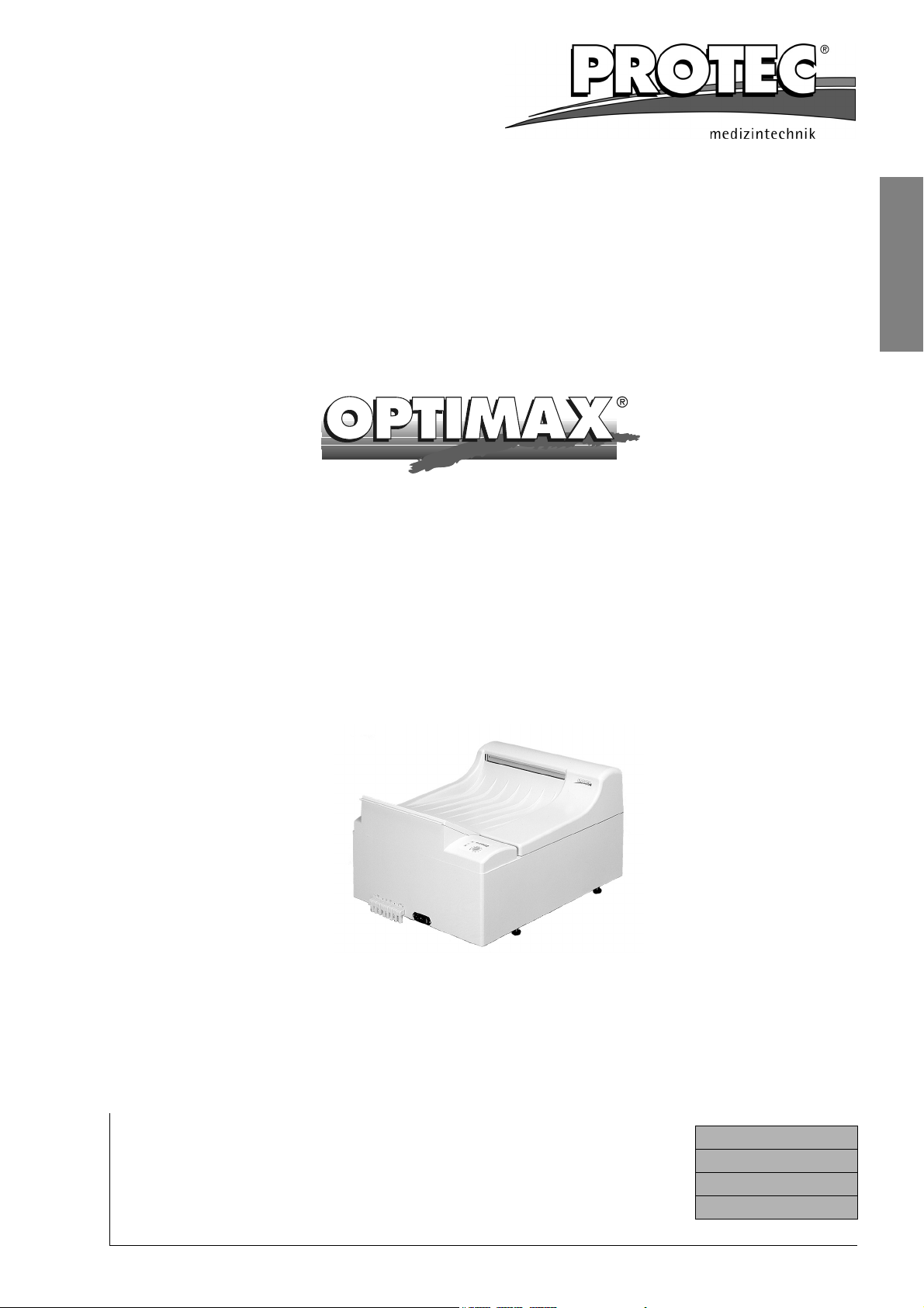
Film Processor
Operation Manual
English
PROTEC® Medizintechnik GmbH & Co. KG
Lichtenberger Straße 35, D-71720 Oberstenfeld, Germany
Telephone: +49-7062-9255-0 e-mail: [email protected]
Machine No.:
Type:
Date of Installation:
Issued: 05-2006/3.4
Subject to technical alterations
Page 2
EU-Declaration of Conformity
EU-Declaration of Conformity
PROTEC® Medizintechnik declares, that the product
Description:
OPTIMAX
®
Machine type:
Model no.
conforms to the following harmonized standards:
Safety:
EMC:
according to the regulations of:
X-Ray-Film Processor
117x-y-0000
x is a number between 0 and 9, y is a number between 1 and 9
IEC 61010-1:2001 + A1:92 + A2:95; DIN 1988 T4:12/1988; UL 3101-1; CSA 22.2-1010-1
EN 50081 Part 1, 03/1993; EN 50082 Part 1, 03/1993
• the Medical Device Directive 93/42/EEC “class 1”,
• the Low Voltage Directive 73/23/EEC and the
• EMC Directive 89/336/EG
PROTEC® Medizintechnik GmbH & Co. KG, Lichtenberger Straße 35, D-71720 Oberstenfeld, Germany
Supplementary
Guidelines:
Place and date of issue
Oberstenfeld, 23. Mai 2006, Jochen Krupp (Technical Manager Analogue Systems)
• DIMDI: DE / 0000042967
• WEEE: DE 55471807
2 OPTIMAX
®
Page 3

Table of Contents
Introduction .......................................................................................................... 3
Technical Specifications ..................................................................................... 4
Safety Instructions............................................................................................... 5
Installation ............................................................................................................ 6
Initial Operation.................................................................................................... 9
Operation
Short overview and control panel ................................................................ 10
Switching the machine on............................................................................ 12
Stand-by mode ............................................................................................ 12
Bath temperature......................................................................................... 12
Display “Film feed”....................................................................................... 12
Manual pumping .......................................................................................... 12
Anti-crystallisation function / Time replenishment ....................................... 12
Automatic replenishment ............................................................................. 13
Rollfilms and paper films ............................................................................. 13
Care
Daily Care.................................................................................................... 14
Weekly Care ................................................................................................ 14
Thorough Cleaning ...................................................................................... 15
Maintenance / Disposal ..................................................................................... 16
Problems and Solutions
Troubleshooting Film Defects...................................................................... 19
Troubleshooting Machine Errors ................................................................. 20
Accessories ........................................................................................................ 21
Service Manual as appendix, see page 23
®
English
Copyright
© 2004 by PROTEC
the limitation by the copyright law, needs written authorization by PROTEC® Mediz-
intechnik.
Information on Liability
This manual has been checked for correctness. The instructions and specifications
were correct at the time it was published. Future models may have modifications
without prior notice. PROTEC
age caused direct or indirect by error, omission or non-conformity of the manual.
Caution (U.S.)
Federal Law restricts this device to sale by or on the order of a medical professional.
®
Medizintechnik. All rights reserved. Any reproduction, out of
®
Medizintechnik does not take responsibility for dam-
Introduction
The OPTIMAX® processor is a compact, automatic table-top processor. Due to the
precision roller transport system, both sheet and roller films can be processed. The
film materials are developed, fixed, rinsed and dried. The OPTIMAX
an automatic film-registration and a Stand-by mode. The developing solutions are
temperature-regulated, circulated and automatically replenished.
This Operation Manual contains the most important instructions for installation, operation and servicing of this machine. Please read the provided information carefully to ensure reliable and satisfactory operation of your OPTIMAX
®
incorporates
®
.
OPTIMAX
®
3
Page 4

Technical Specifications
Technical Specifications
®
Film transport:
Film formats:
Processing capactiy:
Process time:
Linear speed:
Developer time:
Tank capacities:
Continuous roller transport system
In general: Sheet and roll films up to 35.8 cm
(14.1’’) width;
roll films with leader from 70 mm (2.8’’) width;
smallest film format 10x10 cm (4x4’’).
Mammography Type 1171: For processing Mammography Films.
Graphic-Arts Type 1172: With cassette box
(LxWxH) 35x13x12 cm (13.8x5.1x4.7’’) for
processing roll films.
129 films 24x30 cm (10x12“) per hour (standard
model, film fed in crosswise)
Standard 90 s
Mammography 135 s
*Option 167 s
Standard 56 cm/min. (22 in/min)
Mammography 37 cm/min (14.5 in/min)
*Option 30 cm/min (11.8 in/min)
Standard 25 s
Mammography 37 s
*Special 46 s
Developer, fixer and washing 5 litres each (1.3 gal)
Circulation system:
Replenishment:
Developer temperature:
Fixer temperature:
Water connection:
Water consumption:
Drain capacity:
Noise level:
Heat emission:
Environmental conditions:
Developer and fixer are continiuously circulated by
a circulation pump
Automatic replenishment by film detection, in relation to film length
Adjustable 28 - 37 °C (82.4 - 98.6 °F)
Adjusted to developer temperature by heat
exchanger.
Permissible water pressure 2 - 10 bar
(29 - 145 psi), permissible water temperature
5 - 30 °C (41 - 86 °F).
1.9 litres per minute (0.5 gal/min) when processing.
7 litres per minute (1.85 gal/min)
Less than 58 dB(A).
Stand-by: 0.1 kJ/s Processing: 1.4 kJ/s
1) Temperature 18- 40 °C (51,6 - 104 °F), ventilated room, room temperature should be lower
than set bath temperature.
2) Relative humidity lower than 80% up to 31 °C
(80 °F), linear decreasing to 50% at 40 °C (104 °F)
3) Height above sea level less than 2000 m
(6666 ft.)
4) Indoor use
Pollution degree:
2
4 OPTIMAX
®
Page 5
Technical Specifications
®
System protection:
Power source:
Power consumption:
Weight (processor):
Dimensions (LxWxH):
Floor space required:
* Depending on machine type and used gears processors have different speeds.
** Height incl. optional working table resp. base cabinet.
IP 20
Electrical specifications are indicated on model
nameplate.
Type 117x-1-0000: 220 - 240 V~, 8.8 A, 50 Hz.
Type 117x-2-0000: 220 - 240 V~, 8.8 A, 60 Hz.
Machine tested for overvoltage category II according to IEC 1010 (EN 61010, VDE 0411)
Type 117x-4-0000: 110 / 120 V~ ±10%, 15 A,
60 Hz.Machine tested for overvoltage category II
according to UL 3101 and CSA 22.2-1010
Stand-by: 0.12 kWh
Processing: 1.4 kWh
Empty 35 kg (77 lbs)
Filled 50 kg (110 lbs)
77x59x42 (** 112) cm 30.3x23.2x16.5 (** 44.1)’’
2
0.45 m
(4.8 sqft)
Safety Instructions
English
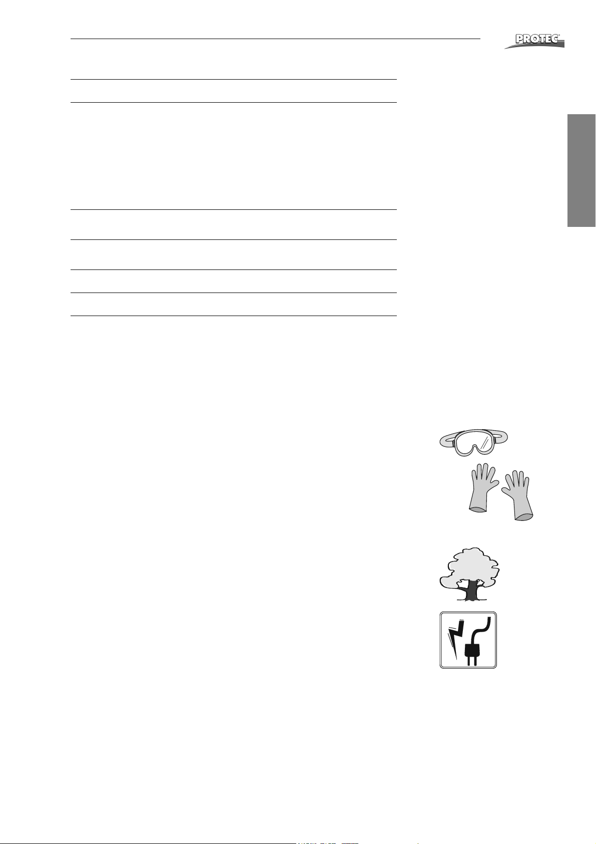
To ensure the safe operation of this processor, installation and use should
always conform to the instructions contained in this manual.
The developer and fixer chemicals used in the processor should be handled
according to the manufacturer´s instructions. In general: Non-diluted chemicals
are caustic. For this reason, chemicals should be handled very carefully. Avoid
contact with skin, always wear protective clothing, gloves and glasses when handling the chemicals - for example, when mixing and refilling. Also when taking the
racks out for cleaning or servicing. In case of chemicals getting into the eyes,
rinse eyes immediately with cold, running water for approximately 15 minutes,
and contact a doctor afterwards. Inhalation of chemicals can be dangerous to
your health and should be avoided. For this reason, always ensure that the room
in which the processor is installed is adequately ventilated.
Environmental regulations regarding the storage and disposal of waste chemicals should be obtained from the local water authorities and complied with.
Before opening the processor switch off the unit and unplug it from the electrical
socket. Service and repairs must be performed by trained service technicians
only. Use only manufacturers replacement parts.
OPTIMAX
®
5
Page 6
Installation
Installation
1. Requirements for installation
a. Fresh water connection: Stop cock with 3/4" outer-thread diameter (washing
machine connection), Water pressure 2 - 10 bar (29 - 145 psi).
Drainage connection: Plastic tube - inner diameter 50 mm (2”) or larger. A
ventilated syphon which serves as odor preventor should be included in the
planning. The drainage tubes should be installed with a fall of minimum 5 %.
Local Water Authorities regulations should be complied with.
b. Electrical connection: Fused wall socket with ground connection according to
electrical data (see Technical Specification, page 5). It is also required to
install a ground fault interrupt (with 25 A / 30 mA nominal error current).
Electrical connections should be carried out according to regulations by an electrician.
2. Set up of processor
Unpack the Processor. Remove cover and transport securing brackets on the sides
of the roller racks. Remove roller racks - start with the dryer rack.
In 220-240 V version the OPTIMAX® is delivered as a tabletop processor with a two
part floorplate. If the machine is upgraded with the optional stand or cabinet, the
small plastic strip has to be removed.
In 110-120 V version the OPTIMAX®is delivered as a tabletop processor with a
three part floorplate. If the machine is upgraded with the optional stand or cabinet,
both small plastic strips and the metal plate have to be removed and a special main
plate must be reconnected.
Table-top installation
In the event that the processor is to be installed on a work top or table, the adjustable feet should be levelled.
®
Attention!
Machine should not be installed on table-top without adjustable feet, as this would block the ventilation openings under the
machine and cause overheating.
Installing on processor stand or base cabinet
In the event that the processor is to be installed on the stand or cabinet (optional
accessory), the processor will be mounted directly to it. Mount processor according
to manual included with stand or cabinet (the adjustable feet inside the accessory
bag are not required).
Finally the processor needs to be leveled:
Place level across the sidewalls of processor and adjust the leveling feet accordingly. Replace the racks into the processor and close the latches.
6 OPTIMAX
®
Page 7
Installation
3. Connecting the processor
®
English
Drainage and
collecting
containers
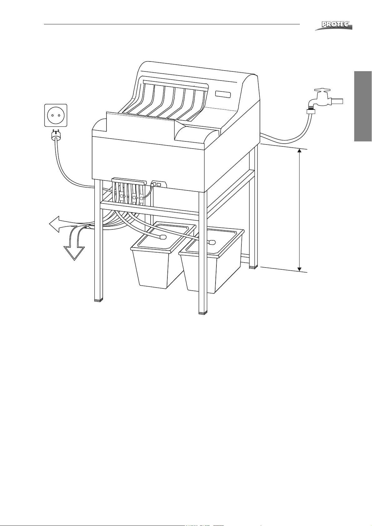
Water connection: Connect the water hose which comes out from the processor’s
back to the fresh water supply.
All other hoses (see diagram page 8): Connect the enclosed hoses according to
color system onto the front of the machine. Put hose clamps (enclosed in accessory
bag) over hose end, before attaching to connection. Warm up hose end (with hot
water or lighter) and push onto the respective connection. Finally push clamp over
hose and connection.
Cut hoses to required length. Then integrate the stop cocks into the three drainage
hoses in such a position, that they are easy to reach.
Connect the suction pipes to the hose ends for the replenishment tanks using hose
clamps. Put suction pipes through cover opening into respective replenishment
tanks and snap them in.
The overflow and drainage hoses from the developer and fixer should be guided
into their respective collecting containers.
The overflow and the drainage of the water can either be guided into the drainage
syphon or into respective collection containers.
min. 70 cm
OPTIMAX
®
7
Page 8
Installation
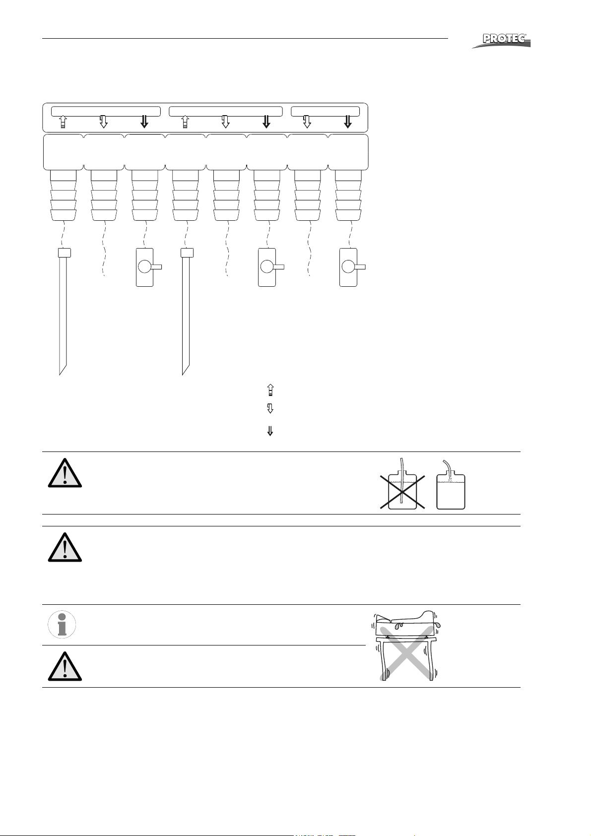
Hose connections
®
DEV FIX
Developer (red) Fixer (blue) Water (clear)
Overflow
Outlet
Replenishment tanks
Pay attention to the correct color connections:
Developer: red
Fixer: blue
Water: clear
Replenishment tanks
Overflow
Overflow
Overflow
Outlet
Replenishment
Overflow
Outlet
HO
2
Outlet
Danger of Overflow!
Use the included cable ties (accessory bag) to secure the hoses. Fix all hose ends which guide into syphon or collecting
container, so that they do not drop into the liquid.
Very important:
The hose piping should be straight (without the hoses going
up and down) with a constant fall. The hoses should be as
short as possible and without bends and kinks. This is very
important for the water overflow hose. Bad piping work will
cause the machine to overflow!
Inform yourself of the local water board regulations regarding
drainage. These regulations may differ from information in
this manual, but they should be complied with.
If the machine is installed table-top, ensure that the table is
stable enough and does not wobble.
8 OPTIMAX
®
Page 9

Initial Operation
Initial Operation
1. Test run
Important!
Processor should not be run dry!
Upon commissioning and every refilling the pumps must be
vented.
®
a. Close the three drainage stop cocks and fill the tanks and replenishment con-
tainers with water. Open water inflow tap. Connect electrical socket and
switch the machine on. Water now flows into water tank. The circulation pump
activates. If fluid does not flow, an air lock may be present. Momentarily open
the drain hose valves to ventilate the system.
b. Ventilation of the replenishment pump:
Set temperature dial to position “Manual pumping”. Keep dial to this position
until no more air bubbles rise in the tanks.
c. Ventilation of the circulation pump:
If air is in the circulation pump, a loud running noise can be heard. Switch the
machine off again. Open the stop cocks of the developer and fixer for five seconds and switch machine on again. Repeat this procedure until no more air
bubbles are visible in the developer and fixer baths and until the circulation
pump runs quietly.
d. Check all hose connections for leakage. Switch machine off and drain water
out.
2. Fill processor with chemicals
Prepare chemicals inside the replenishment containers according to manufacturers
instructions.
Fill up processor manually
By using a suitable container, pour chemicals into the respective tanks. First the fixer and then the developer. Caution: when filling, be sure that chemicals do no
splash from one bath into another. When fixer solution is mixed with developer solution, the developer chemical is destroyed.
Snap each suction pipe into the respective cover of it’s replenishment container and
close it carefully. Place containers under processor.
Using replenishment pump
Filling of processor can also be done by use of the replenishment pump (this takes
much more time). Snap each suction pipe into the respective cover of it’s replenishment container and close it carefully. Place containers under processor. Now set
temperature dial to “Manual pumping”. Keep dial in this position until tanks are filled.
After 20 minutes this function stops automatically - to restart a cycle, turn dial to another position and return to “Manual pumping”. Limitation: The function may fill up
tanks of developer and fixer to different levels. This may be due to different causes.
If this happens, then use a suitable container to fill up the tanks completely.
English
OPTIMAX
®
9
Page 10
Operation
Operation
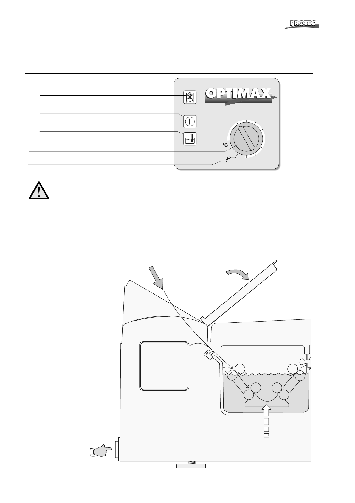
Short overview and control panel
LED displays
• Film feed
Wait with the next film until light goes off.
• Power
When power is on the LED lights up.
• Bath temperature
Flashes when temperature is not reached.
Temperature dial
Manual pumping
Important!
Safety function stops film transportation when cover is removed. Therefore keep cover placed on the machine when
processing films.
28
29
30
31
37
®
®
32
33
34
35
36
*Only machines with cassette box:
When processing roll films in cassettes, pull approx. 10 cm of film out of the cassette and fold the corners. Place cassette into cassette box and feed film into the
infeed. Notice that on processors with cassette box, the film switch is located in the
middle of the infeed.
Film input Light protection cover
Control panel
*Roll film cassette
Film
switch
Developing
Replenishment Developer
Replenishment Developer
Power switch
10 OPTIMAX
®
Page 11
Operation
Attention:
Upon first operation and each refilling of a developer check
the function of the circulation pump and vent the pump if required (see page 9).
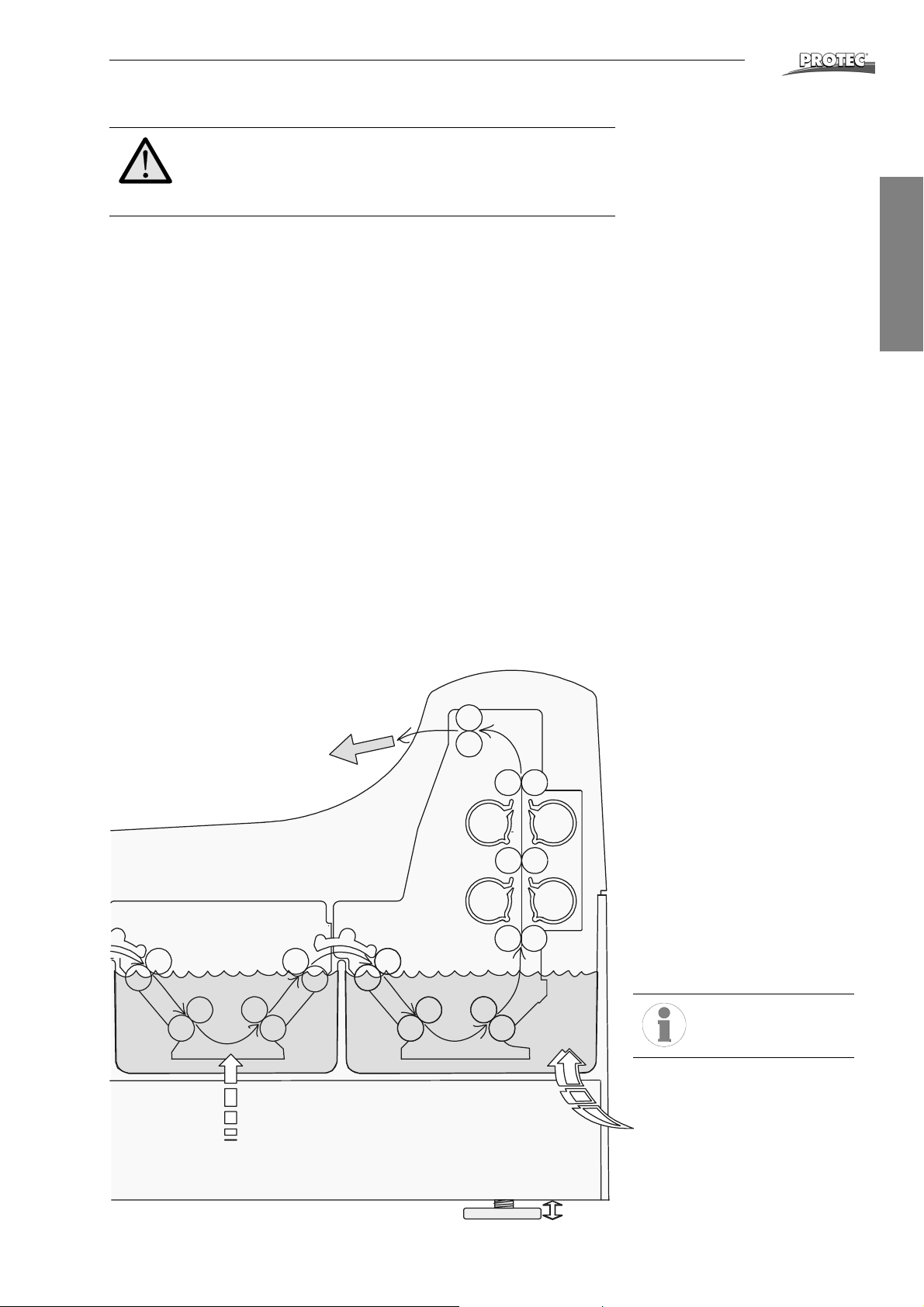
Before use...
1. Close water-drainage stop cock.
2. Open water tap.
3. Switch processor on.
4. Check liquid level in replenishment and drainage collecting containers.
5. Wait until the developer temperature is reached. If the temperature has not
been reached, the bath temperature light is flashing.
6. Run cleaning films through processor.
Working procedure
7. Processing films:
Open light protection cover. Important: Put film first on left side of feed tray
and then feed in. During processing films please watch the display “Film
Feed”. If this is lit, wait until it goes off again and an audible tone can be
heard, before inserting the next film.
®
English
After work...
8. Switch processor off.
9. Close water tap.
10. Open water-drainage stop cock and drain water out of the machine.
Film exit
Drying
Fixing
Washing
Do not place any
object on the processor.
Replenishment Fixer
OPTIMAX
Fresh water inflow
®
11
Page 12

Operation
Stand-by mode
When no film is being processed, the machine switches to Stand-by. The chemicals
remain at a constant temperature. The film transport and water inflow activate at intervals to avoid crystallization of the chemicals on the transport rollers. Entry of the
next film is possible at any time.
Switching the machine on
The processor is switched on at the main power switch on the front side. After
switching on, the water tank will be filled up and a replenishment cycle will be carried out. The developer will be heated up. Until the tempearture is reached the LEDdisplay “Bath temperature” will be flashing. When the processor is ready and the
bath temperature reached, a long signal tone can be heard.
Bath temperature
The processor heats up the chemicals automatically to the dial-set temperature.
When this temperature is reached for the first time after switching on the machine,
a long signal tone can be heard. This is also the case when the temperature is
changed by the dial switch.
If the difference between actual and dial-set temperature is more than 1 °C, the
bath temperature LED will flash. If a film has been fed in and the temperature is not
reached, a warning sound will be heard.
®
Display “Film feed”
If films are fed into the processor without clearance one after an other, then this may
cause a film jam. The light “Film feed” is on during feeding of a film. After the film
has been fed in completely the light goes off. Additionally an audible tone indicates
that the next film can be fed in.
Manual pumping
The function “Manual pumping” activates the replenishment pump and it pumps
chemicals into the tanks in addition to automatic replenishment. Turn the dial to the
position “Manual pumping” and chemicals will be pumped into the tanks. This function is only available during stand-by (no film in process). If the dial is left in this position, the pumping function is stopped automatically after 20 minutes. To restart a
cycle turn dial to a temperature and return to “Manual pumping”.
Please note: Films cannot be processed when dial is set to “Manual pumping”. Also
bath temperature is set automatical to 28 °C during “Manual pumping”. After ending
the manual pumping the temperature must be set again by turning the dial. It takes
some time until the temperature is reached (look at the bath temperature display).
Both chemical pumps - fixer and developer - are driven parallel
by only one motor and therefore they operate in unison.
Anti-crystallisation function
During the stand-by mode, the film transport, the dryer ventilation, the dryer heater
and the water inflow are activated every 20 minutes for a period of 20 seconds. This
prevents the build-up of crystals on the rollers.
12 OPTIMAX
®
Page 13
Operation
Time replenishment (Anti oxidation function, Flood replishment)
During the stand-by, the developer chemicals are subject to change which causes
their deterioration. By means of the time replenishment, a replenishment cycle is
activated after 60 minutes without replenishment. The pump runs for 15 seconds.
With this function, the quality of the developer chemicals are maintained even when
standing idle for long periods.
Automatic replenishment
Depending on the processed amount of films the chemicals are replenished automatically. This is done by pumping chemicals from the replenishment containers.
By means of the film-detection switch at the film feed tray, the surface of the processed films are calculated and after
duration is automatically activated. The replenishment quantity per cycle (at pump
setting 100 %) amounts to 150 ml. The chart below shows the replenishment rate
in ml per m
Film width Setting of replenishment pump*
2
surface in reliance on film width and setting of the pump.
2
0,25 m2 a replenishment cycle of 40 seconds
Replenishment Rates
®
English
100%** (85 %) 75 % (62 %)
35 cm
24 cm
18 cm
*Setting at 50 Hz current resp. settings at 60 Hz current are in brackets
**Standard setting
600 ml/m
870 ml/m
1150 ml/m
2
2
2
450 ml/m
650 ml/m
875 ml/m
2
2
2
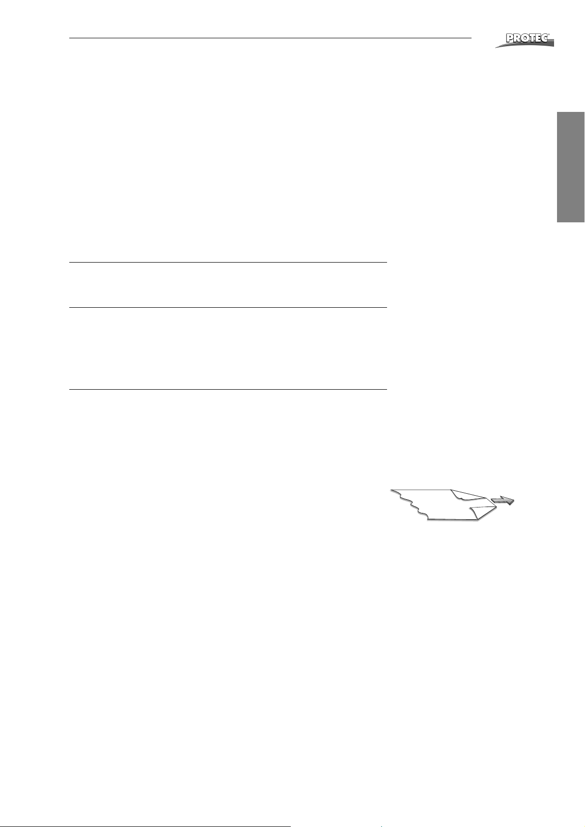
Rollfilms and paper films
Rollfilms can be transported into the machine when a leader film (10x10 cm) is attached, that has been prepared with a chemical resistant adhesive tape.
Rollfilms without leader films and paper should be folded on the corners as per
diagram displayed on the right.
OPTIMAX
®
13
Page 14
Care
Care
Daily Care
Before use...
• Remove dirt and dust from film feed tray with soft, lint-free cloth.
• Run 2 - 3 cleaner films through processor to remove all accumulated dirt and
dust from the rollers.
• Check the fluid level in the replenishment containers and if necessary refill.
After use...
• When work has been completed at the end of the day, drain water out of the
machine. This avoids the growth of algae in the water.
Attention: To prevent damage to the processor, avoid liquid
contact, except for designated areas such as the processor
tanks. Use extreme care to prevent any liquid contact with the
processor controls.
Weekly Care
The developer chemicals cause residue buildup in the machine. This residue has a
negative effect on the developing process of the film material. For this reason the
processor should be regularly cleaned. Proceed as follows:
1. Switch machine off and remove cover.
2. Loosen the securing latches (red, blue and beige) of the drive shafts of each
roller rack at the right side.
3. Remove the roller-racks. First of all remove the large dryer-rack (beige). The
racks are easier to remove and insert when they are slightly tilted. Use the
grey drip catcher forms to ensure that no chemicals splash when being carried. Then remove the fixer (blue) and developer (red) racks in sequence.
4. Rinse all racks thoroughly under warm running water and then leave to drain
off. It is advisable to use a soft sponge (do not use scouring-pad, as this
would scratch the rollers) and remove any dirt from the rollers.
5. Replace the racks: Red = Developer, Blue = Fixer. Beige = Washing/Drying.
Ensure that the racks are firmly installed and do not forget to close the securing latches on the drive shafts.
6. Replace machine cover and ensure it is securely closed.
7. Clean processor outer shell with damp cloth. Do not use aggressive cleaners
or solvents.
®
Please note: When removing the Rinsing / Drying roller-rack,
ensure that no water gets into the film dryer air channel.
14 OPTIMAX
®
Page 15

Care
Thorough Cleaning
Every three months (maybe earlier) a thorough cleaning is necessary, depending
on the quantity of films processed. Tank cleaners are available for developer and
water baths. The fixer bath is cleaned with water. When preparing chemical tank
cleaners, follow manufacturers instructions explicitly.
How to proceed:
1. Switch the machine off and empty all tanks by opening the stop cocks.
2. Remove machine cover. When all tanks are emptied, close stop cocks again.
Now fill the fixer tank with warm water. Prepare cleaner solutions for developer and water baths and fill into respective tanks.
3. Remove suction pipes from the replenishment containers and place them in a
deep container filled with warm water. Attention: Do not add chemical cleaners here!
4. Close machine cover and switch machine on.
5. Start film transportation and keep running for 10 to 20 minutes. To start the
film transport, place a film on the feed tray so that it activates the film switch
but will not be pulled into the processor. During the operation with water, the
installed roller racks will be cleaned.
6. Important: After completion of tank cleaning, the tank should be rinsed thoroughly with clean water. To do this, fill the machine with fresh water twice and
each time, let the machine run for a 10 minute period. Empty the tanks and reclose the stop cocks.
7. Take out the roller-racks and rinse them thoroughly with running water.
Remove remaining dirt from the rollers by using a sponge and clean thoroughly. Doing this, the rollers can be turned by turning the drive shaft.
Remove the sheet metal covers from the dryer rack and clean the rack in
warm water diluted with dishwashing soap, and rinse well after cleaning.
Reinstall the roller-racks in the machine.
8. Refill the tanks with respective chemicals. To avoid accidental contamination,
carefully refill the fixer tank first. If any fixer inadvertendly spills in the developer tank, thoroughly clean the developer tank and then refill the developer
tank. Replace the suction pipes into the replenishment containers. In certain
circumstances the circulation system must be ventilated: see page 9, item 1c.
9. For quality check, process test films.
®
English
Before You Go on Holiday...
When the processor will remain off and unused for periods longer than 2 weeks, the
processor tanks should be emptied. Immediately after draining the chemistry from
the tanks, the drain valves should be closed and water should be added to each
tank. Upon return and prior to use, the processor should be cleaned and filled with
fresh chemistry.
Attention: Do not use alcohol containing solvents to clean the
machine!
Colour changes in the containers are caused by the properties
of the chemicals and no cause for concern!
OPTIMAX
®
15
Page 16

Maintenance / Disposal
Maintenance / Disposal
Maintenance Protocol
Installation
Name: Machine type: Serial number:
Technician: Training: by:
Telephone: Date: Guarantee until:
Parameters Set
Developer temp.: Dryer temp.: Cycle time:
Dev. reg. volume: Dev. reg. volume: Anti-oxidation:
Developer: Fixer: Film type:
Changed by: Date:
Developer temp.: Dryer temp.: Cycle time:
Dev. reg. volume: Dev. reg. volume: Anti-oxidation:
Developer: Fixer: Film type:
Changed by: Date:
®
Developer temp.: Dryer temp.: Cycle time:
Dev. reg. volume: Dev. reg. volume: Anti-oxidation:
Developer: Fixer: Film type:
Changed by: Date:
Maintenance Performed (see page 17)
Maintenance work
performed
Date: Date: Date: Date: Date:
Name: Name: Name: Name: Name:
next maintenance: next maintenance: next maintenance: next maintenance: next maintenance:
Maintenance work
performed
Date: Date: Date: Date: Date:
Name: Name: Name: Name: Name:
next maintenance: next maintenance: next maintenance: next maintenance: next maintenance:
Maintenance work
performed
Date: Date: Date: Date: Date:
Name: Name: Name: Name: Name:
next maintenance: next maintenance: next maintenance: next maintenance: next maintenance:
Maintenance work
performed
Maintenance work
performed
Maintenance work
performed
Maintenance work
performed
Maintenance work
performed
Maintenance work
performed
Maintenance work
performed
Maintenance work
performed
Maintenance work
performed
Maintenance work
performed
Maintenance work
performed
Maintenance work
performed
16 OPTIMAX
®
Page 17
Maintenance / Disposal
Attention:
Never start the machine up unless it is filled with liquid!
Recommended Maintenance Work:
1. Functional check
film intake / film transport / replenishment / bath heating / dryer heating / water supply
2. Cleaning
2.1. Switch off machine, remove cover
2.2. Empty all three tanks
2.3. Close drain cocks and fill tanks with water
2.4. Install cover, switch machine on
2.5. Fill two additional vessels with water, put suction pipes into these vessels and activate replenishment for at
least two minutes (to remove residues of chemicals from replenishing hoses)
2.6. Switch machine on for a few minutes
2.7. Switch machine off
2.8. Empty all tanks
2.9. Prepare tank cleaning agent for developer and water tank according to manufacturer´s instructions
®
English
Attention:
Do not use chlorine containing cleaning agents!
2.10. Fill developer and water tank with tank cleaning agent (do not
2.11. Fill fixer tank with water
2.12. Place suction pipes into empty tanks
2.13. Install cover, switch machine on
2.14. Wait until the operating temperature is reached, approx. 30 °C (observe information concerning temperature,
time, cleaning procedure contained in the datasheet of the tank cleaning agent)
2.15. Activate manual programme and transport
2.16. After approx. 15 minutes (observe information concerning temperature, time, cleaning procedure contained in
the datasheet of the tank cleaning agent) switch film transport off
2.17. Remove cover, neutralise developer tank (observe information concerning temperature, time, cleaning proce-
dure contained in the datasheet of the tank cleaning agent)
2.18. Switch machine off
2.19. Empty all three tanks
2.20. Fill machine with water and switch it on
2.21. Put suction pipes into vessels with water
2.22. Activate regeneration pumps for at least five minutes
2.23. Check all pumps for tightness
2.24. Switch machine off
2.25. Drain tanks
2.26. Fill tanks 3/4 with water
2.27. Switch machine on
2.28. Activate replenishment pumps manually until tanks overflow
2.29. Activate film transport for a few minutes
2.30. Switch machine off and drain all three tanks
use the replenishment pumps to do so)
OPTIMAX
®
17
Page 18

Maintenance / Disposal
2.31. Repeat item 2.20 to 2.30 if required (observe information e. g. concerning temperature, time and cleaning procedure outlined in tank cleaner datasheet)
2.32. Remove roller racks from the machine and remove dirt under flowing water using a soft rag or sponge
2.33. Remove residual dirt particles in tanks and rinsing gutters.
2.34. Clean all toothed gear wheels, axles, bearings and rollers, check them for damage (replace if required)
2.35. Remove light protection flap and wipe its underside using a soft rag
2.36. Clean inlet plate using a soft rag
2.37. Reinstall light protection flap
2.38. Align roller racks and re-insert them in machine
2.39. Fill machine with chemicals
2.40. Switch machine on
2.41. Adjust bath temperature to previously adjusted value
2.42. Feed cleaning film (approx. 4 pieces)
2.43. Check function as described under item 1.
2.44. Approx. 15 minutes after reaching of the set bath temperature, measure it for confirmation and re-calibrate if
required (see operating manual page 39)
2.45. Perform sensitometric test
®
Please dispose of all old devices in an environmentally
friendly manner.
Old devices contain materials which need to be recycled. Please
have them collected separately and recycle appropriately.
18 OPTIMAX
®
Page 19
Problems and Solutions
Problems and Solutions
Troubleshooting Film Defects
Your processor has been constructed for long term use. However, if irregularities
occur, the following information can help to solve the problem. Please check the following items before calling for service.
Films are too light, not enough density
• Bath temperature is too low.
• Developing time too short.
• Exposure time is too short.
• Replenishment rate of developer too low.
• Developer is exhausted or over-diluted: Drain and replace old developer with
fresh developer.
• Fixer solution has been mixed into developer: Renew. Thoroughly clean and
rinse the developer tank before refilling.
• Circulation system is not operating properly.
Films are too dark, too much density
• Developer temperature too high.
• Developing time too long.
• Exposure time is too long.
• Replenishment rate of developer too high.
• Developer chemicals are too concentrated, mix with new developer.
• After replacing the chemicals: Starter is missing.
• Circulation system is not operating properly.
®
English
Films will not dry
• If warm air comes out of air channel in the dryer, chemicals and film type
should be checked.
• Fixer solution is exhausted or diluted.
Film has a yellow-green surface.
• Not fixed correctly. Check the film type and fixer chemistry.
• Fixer solution is exhausted or diluted. Replenishment rate of fixer is too low.
Scratches, pressure marks, dirt on film
• Prior to processing films, run cleaner films through the processor.
• Pressure marks caused by careless handling, finger nails etc.
• Rollers are dirty. Clean tanks and roller racks.
Cloudy film
• Level in developer is too low.
• First guide bar of fixer rack is dirty (condensation or crystals). Clean rollerracks.
• Developer is old or circulation not working.
• For single emulsion film, feed films emulsion (dull) side up.
OPTIMAX
®
19
Page 20

Accessories
Troubleshooting Machine Errors
Machine does not switch on
• Ensure that electrical plug is firmly inserted into socket.
• Ensure that electrical socket has power supply by testing with an appliance
(e.g. tablelight).
Film will not feed in but the dyer fan works
• Place cover firmly on machine, ensuring that the cover switch on the right
front side has been activated.
Machine does not start automatically
• Film switch, located on the left side of the feed tray, has not been pressed
down. Feed in the film to activate the switch.
Developer temperature too low
• The temperature dial is set between two positions.
Replenishment pump does not pump
• Check whether the replenishment containers are full and that the end of the
suction pipe is positioned under the liquid level.
• Check whether there is air in the replenishment pipes. If this is the case, then
check the pipe connections.
®
Rinsing water does not flow
• Open water ball valve.
• Water pressure in the water system is too low: Minimum pressure 2 bar (29
psi).
Water tank overflows
• Water drainage hose (overflow) is bent. The hose end should be positioned
above the drainage level in the syphon (see diagram on page 8).
• Water drainage in the tank, hoses and connections should be checked for
blockage and dirt/residue build-up. The drainage hoses should have a constant fall.
The film does not transport correctly
• Film is fed in and gets caught in the machine: Check the positioning of the
racks in the machine and make sure that the latches are closed.
Important notice:
Ensure that the racks are firmly installed and keep the securing latches on the drive shafts closed.
Don’t operate processor with empty replenishment tanks.
After a long machine shut down check developer and fixer levels and refill if necessary.
20 OPTIMAX
®
Page 21
Accessories
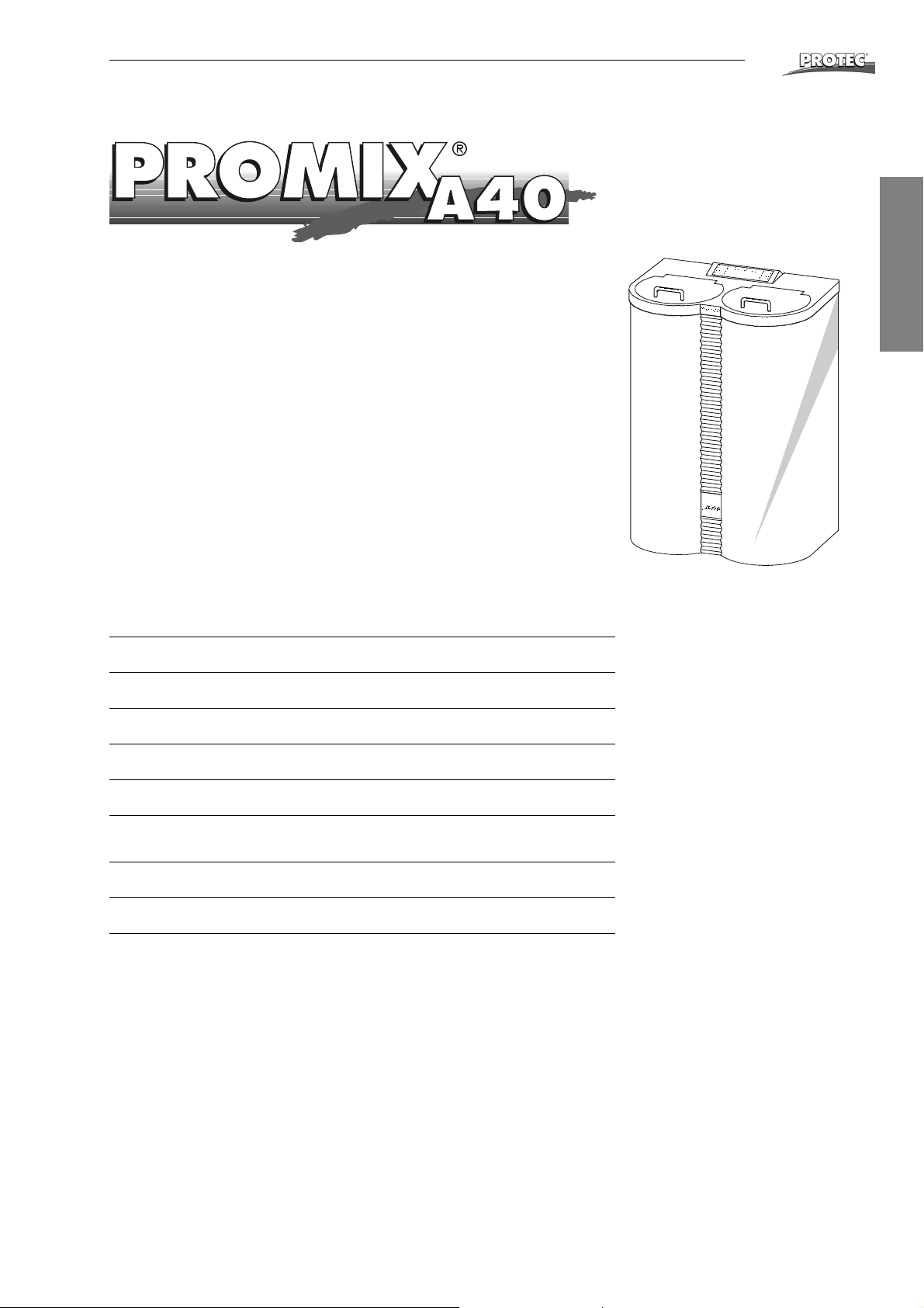
The PROMIX® A40 is a fully automatic chemical mixing machine for preparing
developer and fixer bath chemicals of either powder form or liquid concentrates.
All stages are guided and controlled by means of a microprocessor. Thanks to a
large reserve tank, up to 3 machines can be connected and continue to operate,
without having to interrupt the working process.
®
Due to its patented construction, the PROMIX
fast and virtually service free.
®
The PROMIX
Ask your local dealer for more information.
A40 replaces the usual replenishment tanks in the darkroom.
A40 is easy to operate, reliable,
®
English
Specifications
Tank capacities:
Reserve tank:
Water connection:
Pump capacity:
Mixing times:
Power source:
Weight:
Dimensions:
each 20, 25, 30 or 40 litres
each 13 litres
3/4", 2 - 10 bar (29 - 145 psi)
38 l/min
variable, 2, 3, 5, 10, 15, 20, 25, 30 minutes
220-240 VAC, 200 W, 50/60 Hz
Fuse: sb 2 A / 250 V
28 kg empty, 108 kg full
(WxHxD) 65 x 93 x 44 cm
OPTIMAX
®
21
Page 22
Accessories
At last you can breathe again
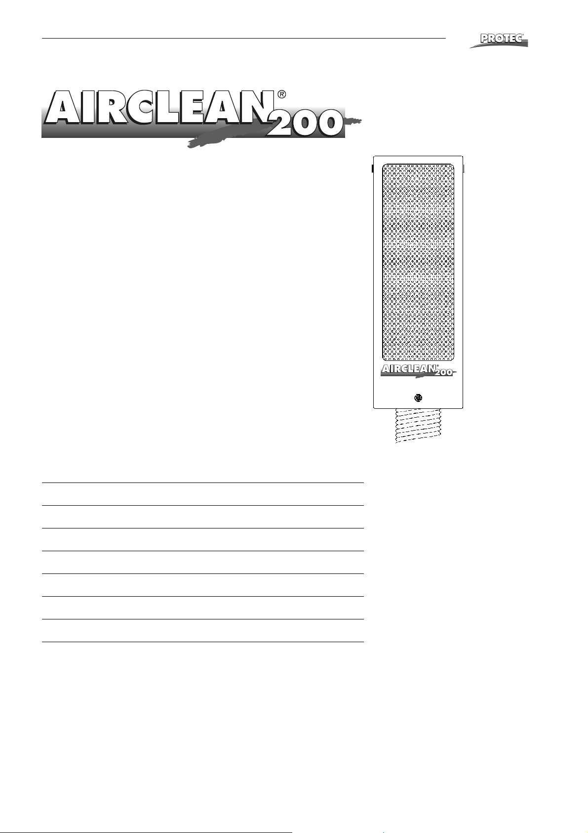
AIRCLEAN® 200 cleans the air from your processor. Unpleasant chemical odors
are absorbed through the large active charcoal filter. Allergies are prevented and
you can breathe again freely.
Simple installation directly on to the processor (no breaking through the wall).
Filter exchange cheap and fast approx. every 3 months.
Ask your local dealer for more information.
®
Specifications
Cleaning capacity:
Filter:
Power consumption:
Power source:
Weight:
Casing:
Casing dimensions:
3
approx. 200 m
Active charcoal
43 W
220-240 V, 50/60 Hz
7 kg
Stainless steel, plastic coated
(WxHxD) 21 x 63 x 17 cm
/hour
22 OPTIMAX
®
Page 23

Service Manual
Table of Contents
Installation Data ................................................................................................. 24
Trouble Shooting ............................................................................................... 26
Spare Parts List.................................................................................................. 31
Electric Diagrams............................................................................................... 37
®
English
OPTIMAX
®
23
Page 24
Installation Data
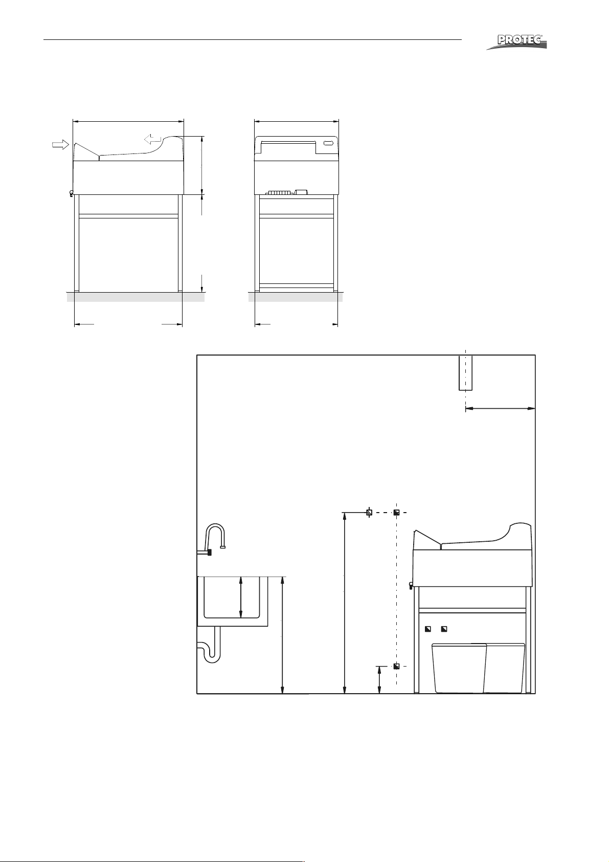
Installation Data
®
77 cm (30.3")
Optional working table or closed base
cabinet (accessory)
75 cm (29.5")
75 cm (29.5“)
1. Wall socket
220-240 V, 16 Aresp. 110 V,
15 A (depending on machine
model). Power lead should be
equipped with Earth-Leakage
Switch, 25 A / 30 mA nominal
error-current. In addition, a
power control switch can be
installed.
2. Fresh water connection 3/4”
with stop cock, permissible
pressure 2-10 bar, water temperature 5-25 °C.
3. Drainage plastic pipe (PVC)
∅ 50 mm (2“) incl. syphon.
4. Drainage resp. collecting containers for used developer.
5. Drainage resp. collecting containers for used fixer.
6. Storing space for replenishment tanks: Below machine or
externally.
7. Ventilation of darkroom is necessary.
8. Sink with freshwater and flexible hose. Inner dimensions
minimum (LxWxH)
60x40x30 cm (24x16x12“).
42 cm (16.5")
42 cm (16.5“„)
70 cm (27.6")
70 cm (27.6“)
Darkroom
8
Sink
60x40 cm (24x16“)
60x40cm (24x16’‘)
)
‘
m
’
c
2
0
1
3
(
59 cm (23.2")
59 cm (23.2")
59 cm (23.2“)
)
‘
’
4
3
(
m
c
5
8
85 cm (34“)
)
‘
’
1
5
(
m
c
0
3
1
130 cm (51“)
20 cm (8“)
12
)
‘
’
3
8
(
m
c
0
2
7
50 cm (20“)
50cm (20’‘)
4
5
6
Measures and positions are recommendations
24 OPTIMAX
®
Page 25
Installation Data
)
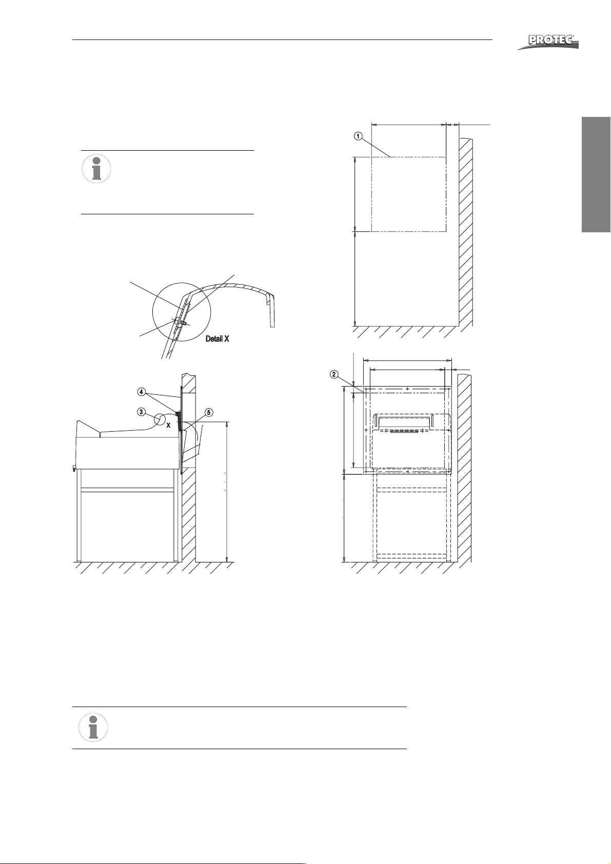
Through the wall mounting “film output”
Film output to the light room for OPTIMAX
Type 11 7 x - y-6000
®
processor
®
553 (21,7”) min. 100 (3,9”
All dimensions refer to PROTEC®
base table OPTIMAX
®
(1267-0-0000)
Dimensions in mm
Blind plate
1176-0-0607
Screw
M4x20
3079-8-5043
Strap
1253-0-0203
)
”
7
,
1
2
(
3
5
5
Wall break through
)
”
7
,
for film exit
7
2
(
5
0
7
English
705 mm (27.7“)
)
”
6
9
,
1
(
0
5
)
)
”
”
7
7
,
,
5
1
2
2
(
(
3
3
5
5
6
5
653 (25,7”)
553 (21,7”) 50 (1,96”)
)
”
9
,
0
4
(
m
m
0
4
0
.
1
Film exit height
1040 mm (40.9“
)
”
8
,
5
2
(
5
5
6
Lower edge of wall plate
655 mm (25.8“)
1. Wall opening according to drawing.
2. Fasten wallplate with enclosed eight screws (note markings).
3. Fix blind plate with screws and straps on the film outlet (Detail X).
4. Push processor up against wallplate and place foam rubber light protection
between processor and wallplate.
5. Hang in film catch basket at wallplate from the backside.
6. Check mounting-set for light imper-meability and function.
Please notice:
Pull sealing wedge off before removing machine cover.
OPTIMAX
®
25
Page 26

Trouble Shooting
Trouble Shooting
Summary
1 Algae ............................................................................................................ 26
1.1 Excessive algae growth in water tank....................................................26
2 General......................................................................................................... 27
2.1 Machine has no power...........................................................................27
3 Drive .............................................................................................................27
3.1 Filmfeed out of order, dryer-fan is working ............................................ 27
3.2 Machine does not start automatically ....................................................27
3.3 Machine doesn't stop automatically....................................................... 27
3.4 Drive motor does not run .......................................................................27
3.5 Transport stops before film comes out, changing the cycle time........... 27
3.6 Processing time and developer temperature relation ............................28
3.7 Changing the transport speed ...............................................................28
4 Bath ..............................................................................................................28
4.1 No circulation in bath .............................................................................28
4.2 Developer temperature too high ............................................................ 28
4.3 Developer temperature too low.............................................................. 29
4.4 Developer temperature too low, fixer temperature too high................... 29
4.5 Removing the turning knob.................................................................... 29
4.6 Calibration of developer temperature .................................................... 29
5 Film defects ................................................................................................. 29
5.1 Films will not dry .................................................................................... 29
5.2 The film does not transport correctly ..................................................... 29
5.3 Scratches, pressure marks, dirt on film ................................................. 29
6 Replenishment ............................................................................................30
6.1 Replenishment pump does not pump or does not pump sufficiently .....30
6.2 Replenishment rates are too high or too low .........................................30
6.3 Adjust replenishment pump ...................................................................30
7 Dryer............................................................................................................. 30
7.1 Dryer fan does not function or runs with reduced speed ....................... 30
8 Water ............................................................................................................30
8.1 Rinsing water does not flow...................................................................30
8.2 Water tank overflows .............................................................................30
®
1Algae
1.1 Excessive algae growth in water tank
• Algae growth inside the water tank is not only anoying, it causes increased
cleaning work and leaves residue on the films. When algae is present, corrective measures are required:
• When work has been completed at the end of the day, drain water out of the
machine.
• Clean dryer-water rack regularly. Use soft sponge and soap to remove residue from the rollers.
• Install a particle filter system in the fresh water supply for the processor.
• If water tank overflows due to algae growth blocking the overflow hose, then
the overflow hose can be attached directly to the connection at the water tank
inside the machine.
• If no other solutions can be found, then usage of Anti-Algae-Agents can be a
great improvement (automatic dispensers work the best). However, it is
known that cleaning agents containing chlorine may corrode rubber rollers
and high-grade steel in the tank area (check before use).
26 OPTIMAX
®
Page 27

Trouble Shooting
2 General
2.1 Machine has no power
• Ensure that electrical socket has power supply.
• Check machine fuse in main power switch.
• While power switch is on, check the following components: Voltage on contact
of main switch - if no voltage - change main switch. Check input voltage at
electronics. If the voltage is normal, exchange the electronics. if no voltage
check the cable wiring harness.
As replacement fuses, please excusively use PROTEC gold
fuses. These fuses are optimally adapted to the existing conditions.
3Drive
3.1 Filmfeed out of order, dryer-fan is working
• When placing processor cover on, the cover switch should be activated, readjust if necessary.
• Cover switch has no current passage when activated: Replace.
• Check screwing of chain wheel on motor- and driveshaft.
3.2 Machine does not start automatically
• Film switch is not correctly positioned or operator wire is bent. Re-adjust film
switch and operator wire.
• Check following parts: Film switch, wiring of film switch and microprocessor
board.
• Check wiring from electronic to the connections of components (motor, fan,
dryer heating, solenoid valve). If the connections have no fault then electronic
is possibly defective.
3.3 Machine doesn't stop automatically
• Display “film feed” is permanently illuminated: Wire band of film switch is
jammed. Readjust wire.
• Check following parts: Film switch, wiring of film switch and microprocessor
board.
3.4 Drive motor does not run
• Check cover switch.
• Check drive motor: If voltage can be detected on motor, then motor is defective.
• Dryer fan runs but no voltage on motor: Interruption in the wiring.
3.5 Transport stops before film comes out, changing the cycle time
The cycle time is the processing time which turns off after a film has passed the film
switch. Activate the switch in the feed tray with a film and remove the film. Measure
the time until the processor stops automatically.
Following times can be measured (+/- 5%):
®
English
Standard machine: 125 s Jumper 2-3
Mammography: 155 s Jumper 1-2
Optional type: 190 s Jumper removed
Change cycle time if necessary. This can be accomplished by changing the position
of the jumper on the upper side of the electronics.
OPTIMAX
®
27
Page 28
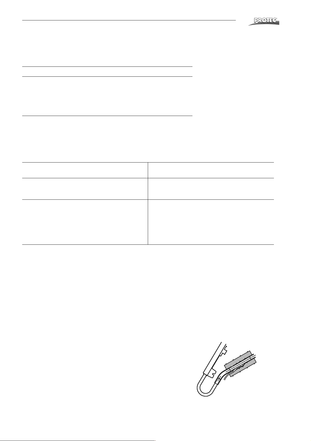
Trouble Shooting
3.6 Processing time and developer temperature relation
The following chart demonstrates guide value relations between developer temperatures and processing times. Variations are possible depending on the various films
and chemicals. Changing the transport speed see 3.7.
Processing time "Dry to Dry" Developer temperature
105 s 32 °C - 34 °C
118 s 32 °C - 34 °C
135 s 31 °C - 33 °C
143 s 30 °C - 32 °C
167 s 30 °C - 32 °C
3.7 Changing the transport speed
The processing speed can be changed by changing the gear wheels. To do this the
tanks need to be emptied and the machine be turned over. After removing the drive
motor the chain gears can be changed. Please note that the jumper on the PCB
needs to be placed to the indicated position.
Following gear combinations are available:
®
220-240 V, 50/60 Hz-Versions
110-120 V, 50 Hz-Versions
tGmGsJumper
position
105 t=17 t=16 2-3 29 48 105
118 t=16 t=17 1-2 32 43 113 14 17 2-3 31 17.6
135 t=14 t=17 1-2 37 37 124 12 16 1-2 34 16.0
143 t=14 t=18 removed 39 35 132 12 17 1-2 36 15.0
167 t=12 t=18 removed 46 30 139 12 18 1-2 38 14.3
t = Processing time in seconds
Gm = Chain wheel on motor shaft
Gs = Chain wheel on drive shaft
Devel-
oper time
(s)
Infeed
speed
(cm/min)
tGmGsJumper
(90)
110-120 V, 60 Hz Versions
Devel-
position
14 16 2-3 29 18.9
oper time
(s)
Infeed
speed
(in/min)
4Bath
4.1 No circulation in bath
• Circulation pump works but no circulation in bath: Air lock in heating and circulation system. Ventilate pump (see Page 9).
• Particles in the pump chamber. The pump chamber can be easily opened by
removing the four clips. When closing again ensure that the rubber seal is
positioned correctly and not damaged.
• Check connection of pump, circulation pump possibly defective.
4.2 Developer temperature too high
• Check attachment of temperature sensor. This should be firmly positioned on
tube and completely covered with foam rubber.
• Check sensor: At ambient temperature voltage between pin 3 (green) and
pin 2 (brown) must be between 0.1 and 0.5 V.
• If the sensor has no fault then the microprocessor board is defective.
28 OPTIMAX
®
Page 29
Trouble Shooting
3
4.3 Developer temperature too low
• Check circulation pump. Air lock in the circulation pump: Ventilate pump (see
Page 9). If no circulation can be detected: Check wiring of circulation pump,
pump possibly defective.
• Developer is not heated: Check temperature safety switch on heat-exchanger.
Check heating element: Current flow resistance should read approx. 66 Ω
(120 V-heating: 36 Ω).
• Check temperature sensor (see 4.2).
• If no error can be found then the microprocessor board is possibly defective.
4.4 Developer temperature too low, fixer temperature too high
• Air lock in the circulation pump: Ventilate circulation (see Page 9).
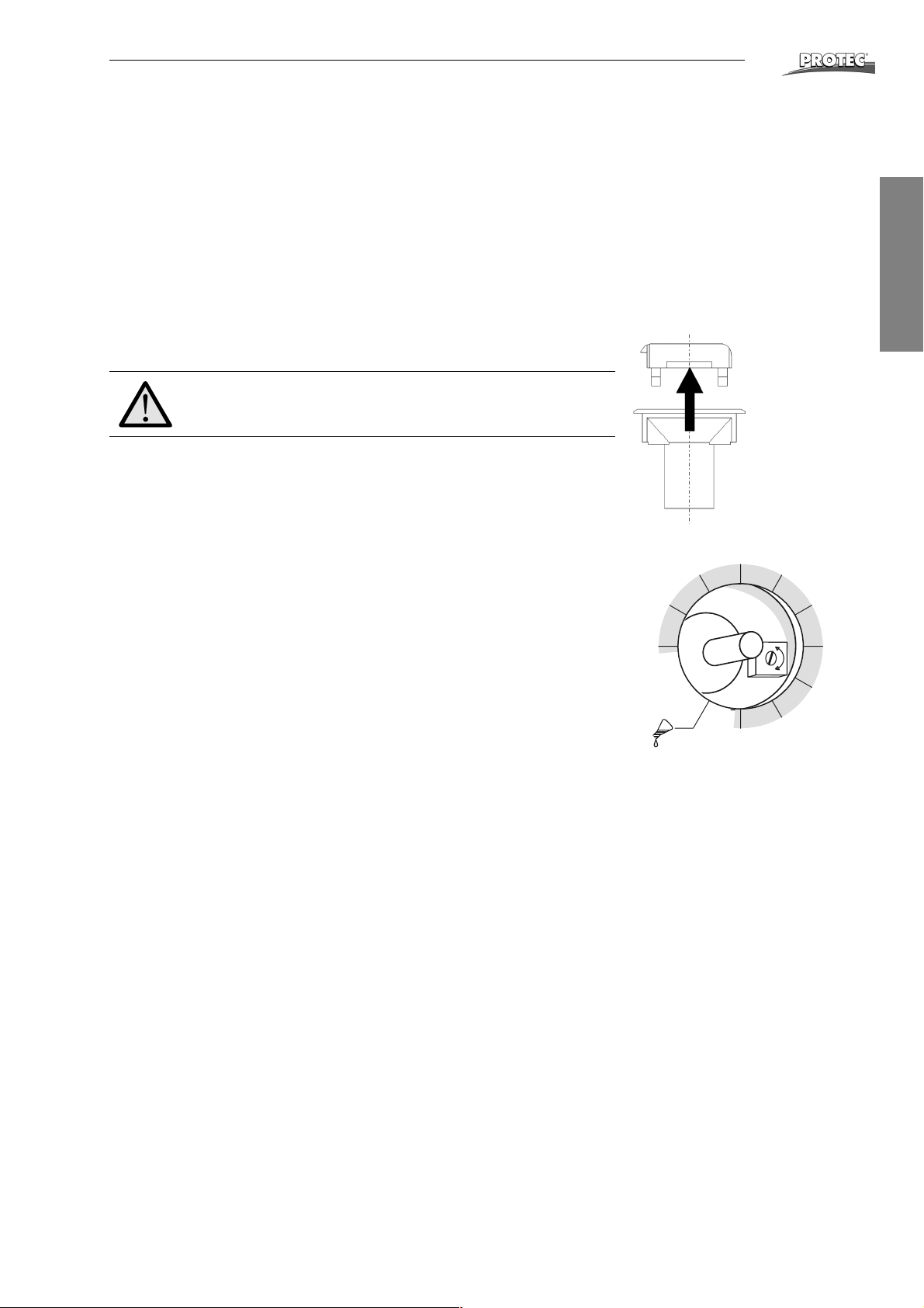
Do not exchange PCB without removing knob!
4.5 Removing the turning knob
• Using flat pliers pull the lever from the knob, while holding the bottom part
(knob) down with the other hand.
• Open the screw of the collet (Attention: don’t open completely) and pull the
knob out.
• When reinstalling the knob turn axis on PCB to end position counter clockwise. Fix the knob in that the pointer is at position of “Manual pumping”.
4.6 Calibration of developer temperature
Deviating temperatures within +/- 1.5 °C can be calibrated by a potentiometer on
the PCB. It can be reached after removing the turning knob (see 4.5) from above.
Turning clockwise decreases the temperature.
5 Film defects
5.1 Films will not dry
• No air comes out of air channel: Check wiring of dryer fan, fan is possibly
defective.
• Cold air comes out of air channel: Check wiring of heating element in the air
channel, heating element possibly defective.
• Hot air comes out of air channel, but the film is still not dried to satisfaction.
Check chemicals and film type. If this leads to no solution then the transport
speed of the machine can be reduced (see Changing the transport speed,
page 28).
29
28
°C
30
31
7
+
-
®
English
32
33
34
35
36
5.2 The film does not transport correctly
• Check the positioning of the racks in the machine and make sure that the
latches are closed.
• Check the roller racks: Position of the guide elements, rollers are in correct
position and are not loose, flat springs are not bent, all gears are in place.
• Motor runs: The worm gear of the drive shaft should be secured with a cotter
pin (see page 29, pos. 38) to avoid twisting. Check the screws and positioning
of the chain and chain wheel.
5.3 Scratches, pressure marks, dirt on film
• Straight scratches in the feed direction indicate faulty guide elements. Check
each rack and straighten up the guide elements. If mechanically damaged,
replace the guide elements.
• Pressure marks caused due to dirty or damaged rollers. Check rollers for visible damage. Rubber rollers sometimes swell. Exchange defective rollers.
OPTIMAX
®
29
Page 30
Trouble Shooting
6 Replenishment
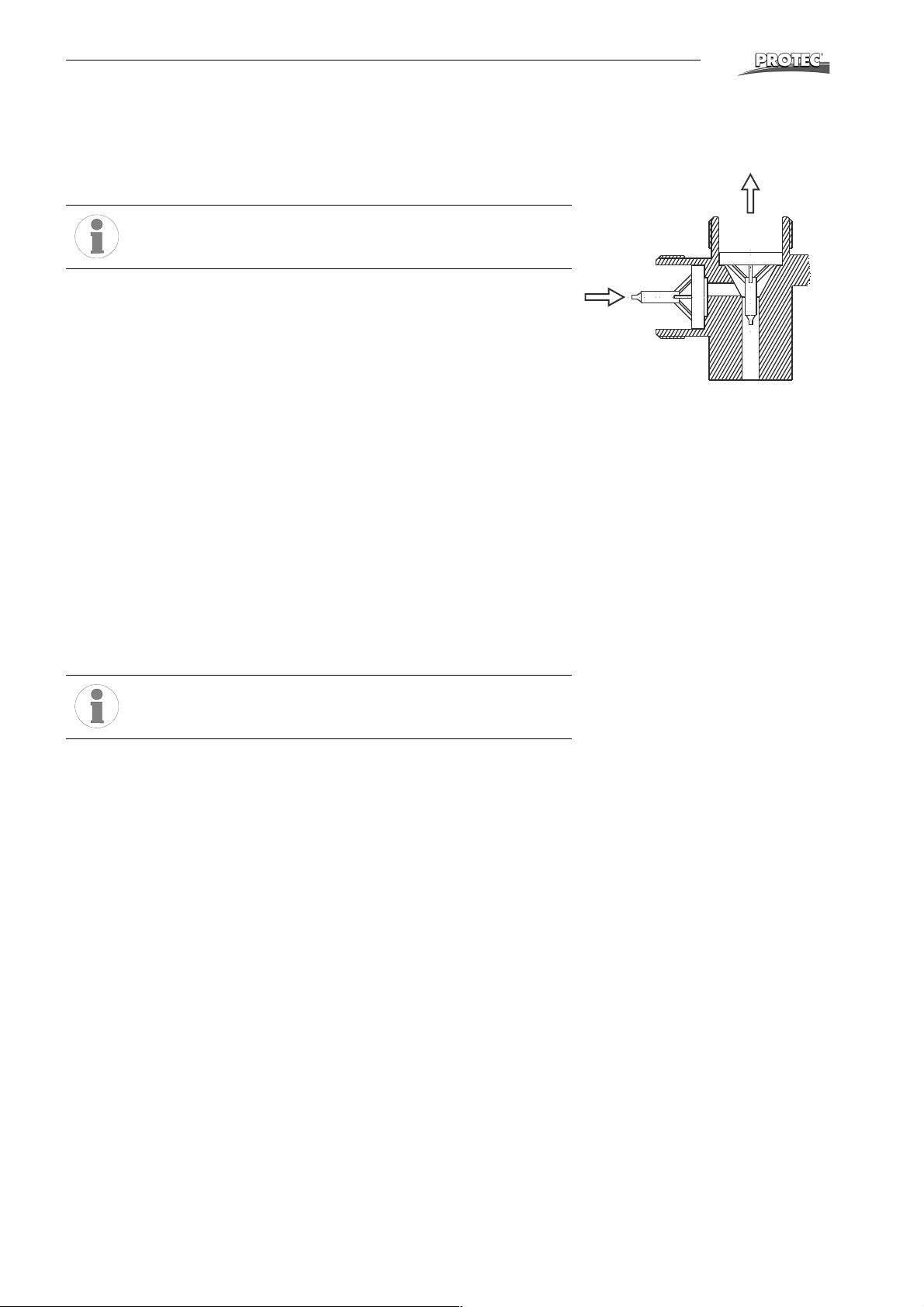
6.1 Replenishment pump does not pump or does not pump sufficiently
• Clean valve inside connection tube.
Install valve insert correctly: Pay attention to flow-through direction!
• Check filter in the suction pipe (repl. container) and clean it if necessary.
• Replenishment pump sucks air in. Check hoses and connections.
• Check eccentric position. Capacity approx. 240 ml/min at setting to 100 %.
(60 Hz: 240 ml/min at 85 %)
• Activate the “Manual pumping” and while on, check the voltage of connection
X2 on the power PCB. If no voltage can be registered - exchange power PCB.
6.2 Replenishment rates are too high or too low
• The replenishment rate can be changed by adjusting the stroke of the pump.
To do this, the eccentric on the replenishment pump must be adjusted. Maximum pump capacity is 240 ml/min(100 %).
®
6.3 Adjust replenishment pump
• For the adjustment of the eccentric first open the allan screw on the big
eccentric with the red line. If the screw is not reachable, then start the “Manual
pumping” (dial switch) for a short time. If the screw is not reachable, momentarily rotate the temperature switch to “Manual pumping”. When the screw is
reachable, quickly turn the temperature switch back to a temperature position.
• Turn the eccentric so that the red line will be at the desired position and fasten
the allan screw.
Minimum setting must not be below 75 %.
7Dryer
7.1 Dryer fan does not function or runs with reduced speed
• Check the correct connecting of the fan cables: bl = blue; bk = black;
br = brown.
• If the fan is connected improperly, then the fan runs only half power.
8 Water
8.1 Rinsing water does not flow
• Water pressure in the water system is too low: Minimum pressure 2 bar
(29 psi).
• Valve activates, no flow passage - filter at inflow is blocked.
• Check green water inlet hose inside the machine.
8.2 Water tank overflows
• Water drainage hose (overflow) should have a constant fall. The hose end
should be positioned above the drainage level in the syphon.
• Check water drainage in the tank and hose for blockage and dirt/build-up.
• When extreme algae growth is present, the overflow can be connected
directly onto the fitting of the water tank.
30 OPTIMAX
®
Page 31
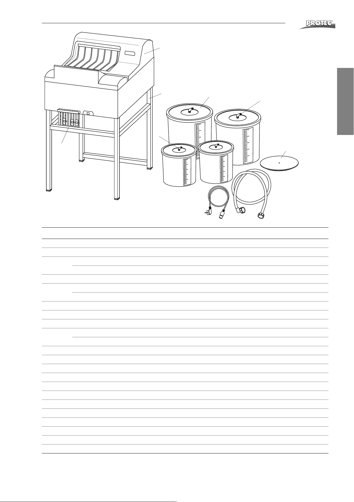
Spare Parts List
®
1
8
9
4
2
3
6
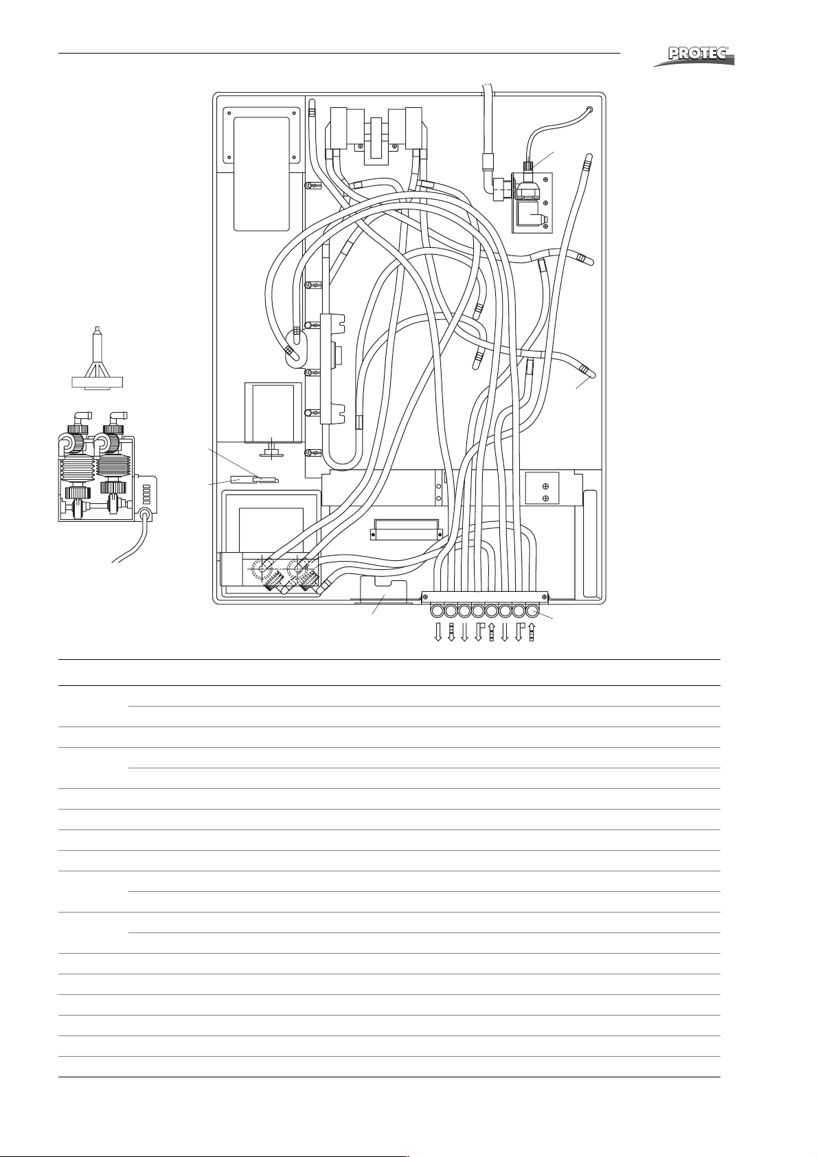
Pos. Order No. Description
1 1170-0-0200 Cover complete
2 2006-0-0005 Drain stop cock 10 mm
3 1170-0-2000 Replenishment tank 12 l dev.
1170-0-2100 Replenishment tank 12 l fix.
4 1170-0-1750 Suction pipe w. filter f. 12 l tank
6 2004-0-0003 Electrical power lead 220-240 V
2004-0-0021 Electrical power lead 110-125 V
7 2018-0-0001 Water inlet tube
8 1267-0-0000 Processor stand
- 1267-0-0010 Closed base cabinet
9 1101-0-2000 Replenishment tank 25 l dev.
1101-0-2100 Replenishment tank 25 l fix.
10 1101-0-1700 Suction pipe w. filter f. 25 l tank
11 1101-0-4100 Floating cover, developer
- 2018-0-0012 Hose 10 x 2 mm, clear, reinforced
- 2018-0-0009 Hose 10 x 2 mm, blue, reinforced
- 2018-0-0008 Hose 10 x 2 mm, red, reinforced
- 2018-0-0005 Hose 4 x 1 mm, green
- 2018-0-0003 Hose 9 x 2 mm, clear
- 2022-0-0004 Tube clamp
- 2022-0-0019 Wire tube clamp
- 2022-0-0026 Wire tube clamp
- 2022-0-0028 Wire tube clamp
- 2015-0-0001 Floating balls
10
English
11
7
OPTIMAX
®
31
Page 32
Spare Parts List
20a
®
21
29
(53)
(61)
28
(30)
26
20
27
25
(58)
20
22-23
Pos. Order No. Description
20 0202-1-0008 Replenishment pump 2KBA 220-240 V, 50/60 Hz
0202-6-0008 Replenishment pump 2KBA 115 V, 50/60 Hz
20a 0002-1-0008 Valve insertion f. pos. 20
21 2002-1-0013 Circulation pump 220-240 V, 50/60 Hz
2002-6-0013 Circulation pump 110 V, 50/60 Hz
22 1170-0-1400 Main switch combi 220-240 V UL
23 2010-0-0010 Fuse, slow blow in gold, 10 A / 250 V UL
22+23 2028-0-0036 Main switch 110-120 V UL
24 1170-0-0702 Angle connection (grey)
25 1170-5-1300 Electronic 220-240 V
0170-6-1300 Electronic 110-120 V
26 0170-0-2400 Micro-switch (cover)
0170-4-2400 Micro-switch (cover) UL
27 2007-0-0010 Operator for micro-switch
28 1101-0-0704 Angle fitting
- 0016-0-0002 PU - glue kit
29 2021-0-0001 Screw-in connector
- 1170-0-1250 Wiring harness V2 230 V
- 1170-0-1251 Wiring harness V2 115 V
24
32 OPTIMAX
®
Page 33
Spare Parts List
34 38 33 32
35
37
®
31
English
35
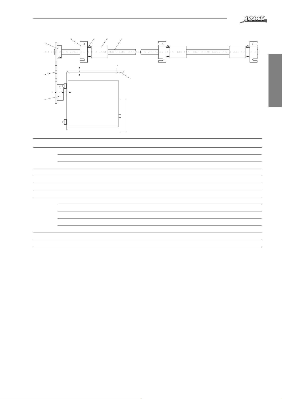
Pos. Order No. Description
30 2001-0-0003 Main drive motor 220-240 V, 50 Hz
2001-2-0003 Main drive motor 220-240 V, 60 Hz
2001-6-0003 Main drive motor 120 V, 50/60 Hz
31 1170-0-1101 Motor bracket
32 1170-0-1501 Drive shaft worm-gear
33 1170-0-1503 Worm-gear
34 1170-0-1502 Bearing block
35 1170-0-1506 Chain wheel t=12
1170-0-1504 Chain wheel t=14
1170-0-1505 Chain wheel t=16
1170-0-1102 Chain wheel t=17
1170-0-1507 Chain wheel t=18
37 2037-0-0002 Chain 6 mm with coupler link
38 3000-9-4013 Cotter pin 2.0x20 mm, inox
30
OPTIMAX
®
33
Page 34
Spare Parts List
®
60
55
54
56
58
61
62
63
59
51
64
50
65
53
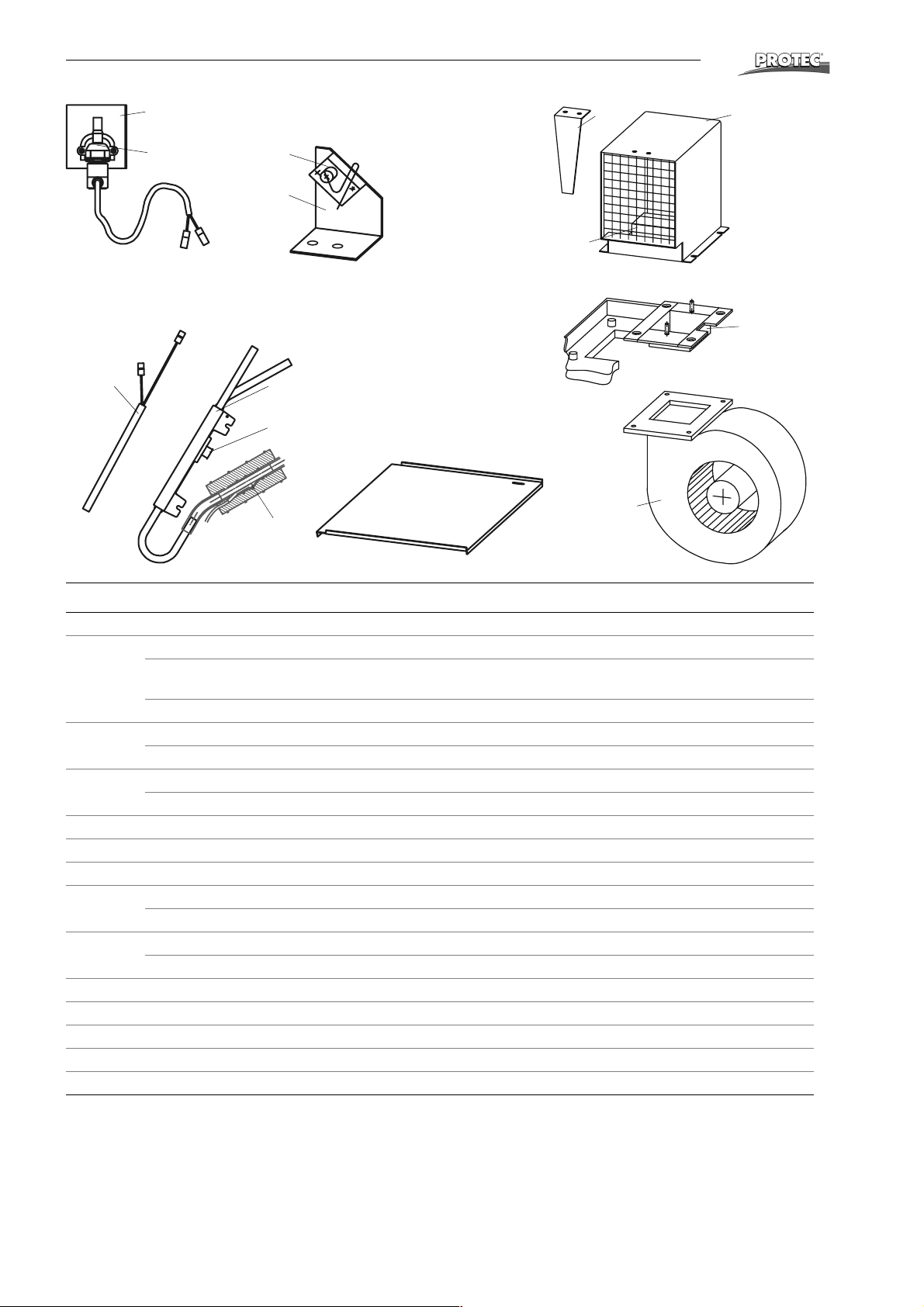
Pos. Order No. Description
50 1170-0-1301 Air channel
51 2003-5-0006 Heating elment 230 V, 1100 W
2003-6-0007 Heating element 110 V, 900 W
standard model
2003-5-0008 Heating element 230 V, 1000 W
53 2008-5-0007 Dryer fan 220-240 V, 50/60 Hz
2008-6-0007 Dryer fan 115 V, 50/60 Hz
54 0170-5-1900 Solenoid valve 220-240 V, 50/60 Hz
0170-6-1900 Solenoid valve 115 V, 50/60 Hz
55 1101-0-0121 Securing bracket
56 0170-0-0800 Micro-rotary-switch for film-detection with operator
58 1170-0-0804 Bracket for micro-rotary-switch
59 1170-0-0105 Film feed tray
1172-0-0105 Film feed tray graphic arts
60 2003-5-0002 Heating element 230 V, 800 W
2003-6-0002 Heating element 120 V, 400 W
61 1130-0-2101 Heat exchanger
62 2005-0-0005 Temperature safety switch mounted on heat exchanger
63 0190-0-2200 Temperature sensor
64 1170-0-1303 Plate for air channel
65 1170-0-1302 Channel dryer heating
34 OPTIMAX
®
Page 35
Spare Parts List
®
100
112
111
113
110
114
103
108
121
117
102
English
104
119
115
116
120
109 122
103
123
106
107
105
104
Standard roller racks
OPTIMAX
®
104
35
Page 36

Spare Parts List
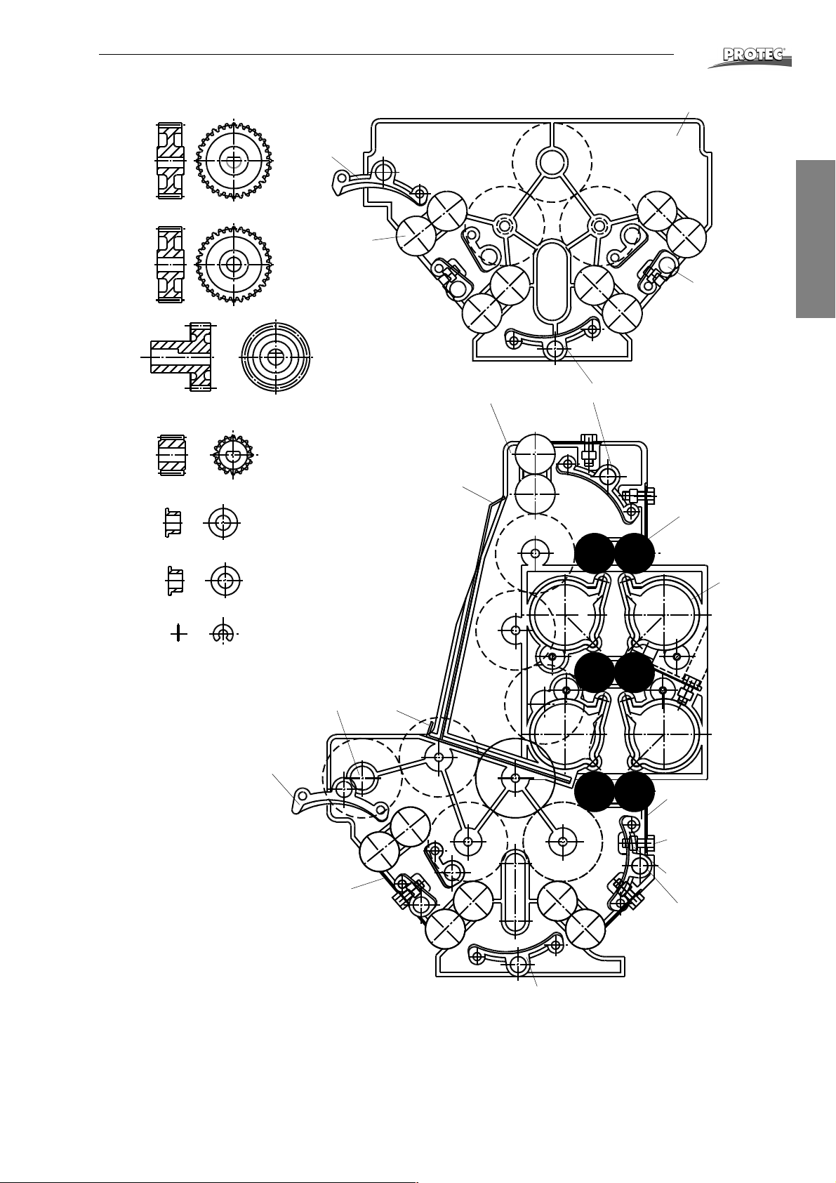
Pos. Order No. Description
Mammography Processor
- 1171-0-0600 Roller rack, dryer
Graphic Arts Processor
- 1172-0-0300 Roller rack, developer
- 1172-0-0600 Roller rack, dryer
Standard Processor
- 1170-0-0300 Roller rack, developer
- 1170-0-0400 Roller rack, fixer
- 1170-0-0600 Roller rack, dryer
100 0170-0-0301 Side plate dev. w. shafts (left)
1170-0-0301 Side plate dev. (right)
0170-0-0401 Side plate fix. w. shafts (left)
1170-0-0401 Side plate fix. (right)
102 1140-0-3800 Guide bar straight, short
103 1140-0-4500 Guide bar with nose
104 1140-0-3700 Guide bar, curved
105 1170-0-0304 Flat spring 55
106 3079-8-5013 Screw M4x10, A4
107 3009-3-4023 Hexagon nut M4, A4
108 1140-0-0301 PU-roller 35 ground
109 1170-0-0310 Drive shaft rack
110 1101-0-0302 Gear t = 16, D-hole
111 1101-0-0304 Gear t = 32, round hole
112 1101-0-0303 Gear t = 32, D-hole
113 1170-0-0302 Wormgear
114 1101-0-0305 Bearing bush
115 1101-0-0317 Bearing bush, black
116 2014-0-0001 Circlip
117 0170-0-0601 Dryer side plate left w. shafts
1170-0-0602 Dryer side plate right
119 1140-0-0302 Rubber roller 35
120 1140-0-0605 Air jet (35)
121 1170-0-0604 Dryer plate, large
122 1170-0-0603 Dryer plate, small
123 1170-0-0303 Flat spring 35
- 0170-0-0004 Maintenance set
®
36 OPTIMAX
®
Page 37
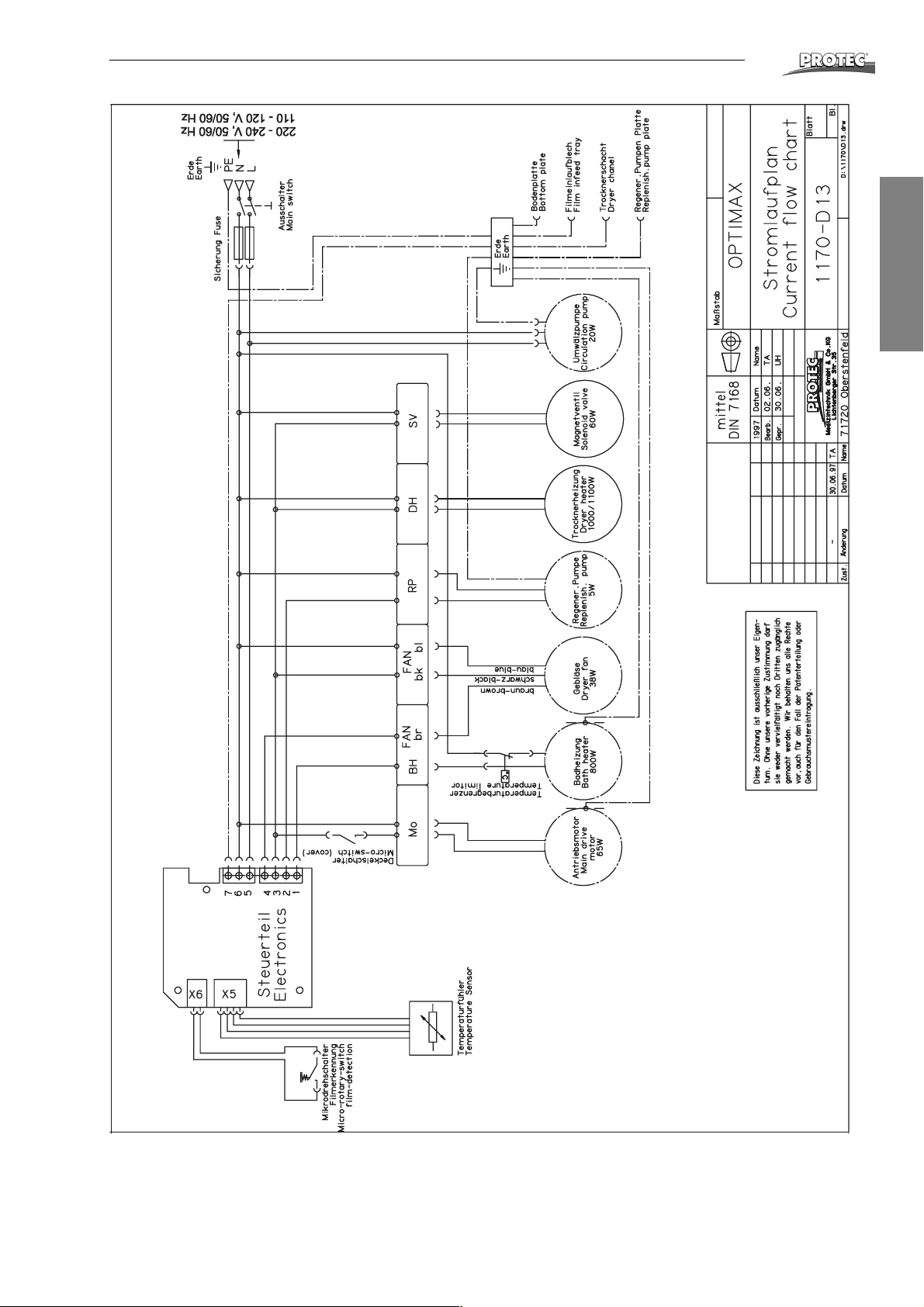
Wiring Charts
®
English
OPTIMAX
®
37
Page 38
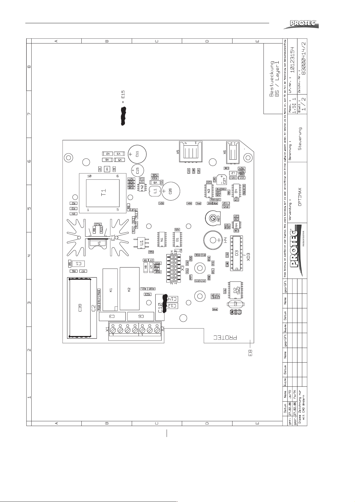
Wiring Charts
®
38 OPTIMAX
®
Page 39
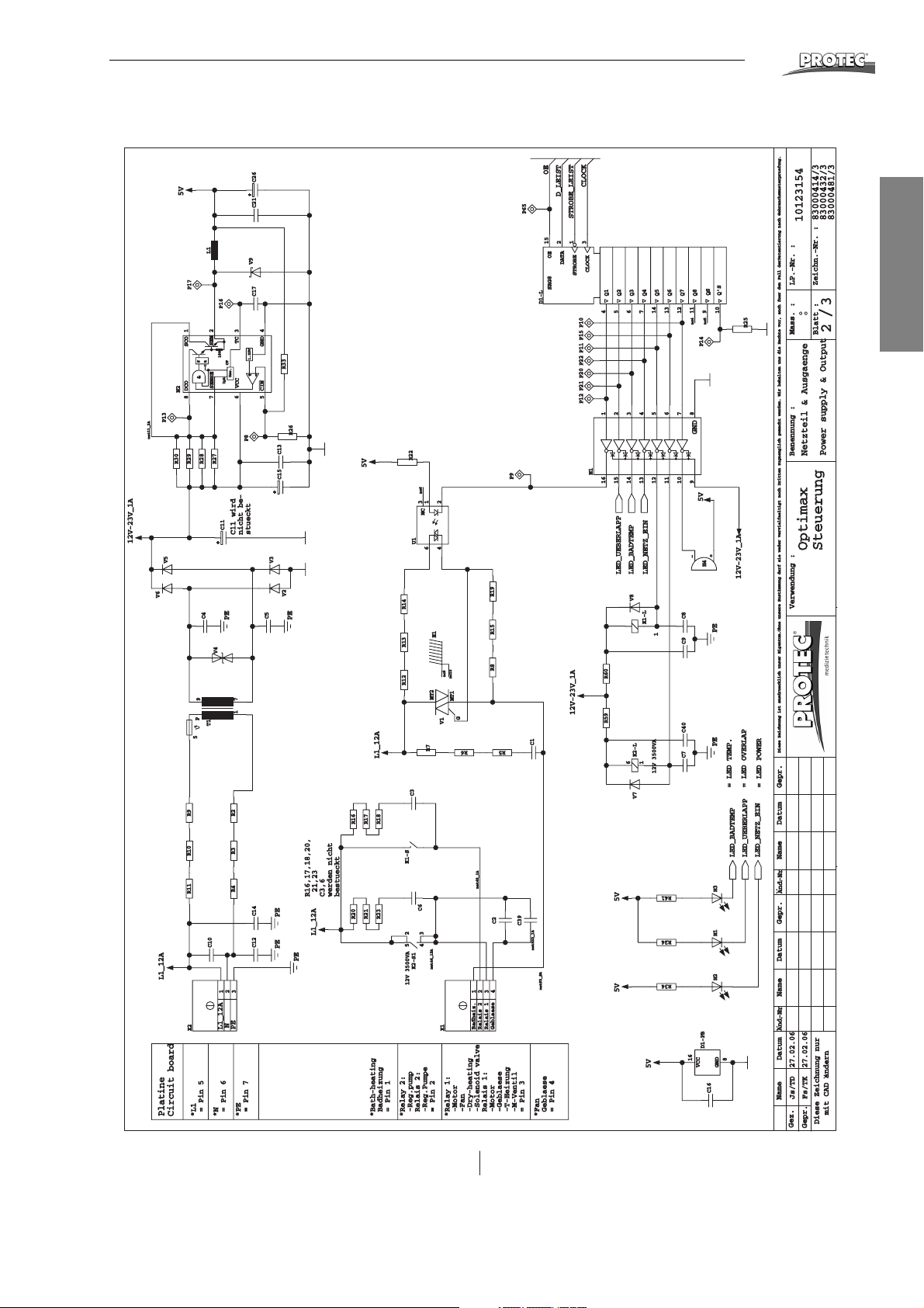
Wiring Charts
CLOCK
STROBE
DATA
OESRG8
QS
Q'S
Q8
Q7
Q6
Q5
Q4
Q3
Q2
Q1
VCC
GND
R6
..
And-Nr
..
And-Nr
Name Datum Gepr.
..
Name Datum Gepr.
..
Name
Datum
Gez.
Gepr.
Verwendung : Benennung :
Blatt :
Mass. :
:
/
Zeichn.-Nr. :
LP.-Nr. :
Diese Zeichnung ist ausdruecklich unser Eigentum.Ohne unsere Zustimmung darf sie weder vervielfaeltigt noch Dritten zugaenglich gemacht werden. Wir behalten uns die Rechte vor, auch fuer den Fall derPatentierung nach Gebrauchsmusterpruefung.
Diese Zeichnung nur
mit CAD andern
..
Netzteil & Ausgaenge
Power supply & Output
Optimax
Steuerung
Platine
Circuit board
R7
23
*L1
= Pin 5*N= Pin 6
*PE
= Pin 7
*Bath-heating
Badheizung
= Pin 1
*Relay 2:
-Reg.pump
Relais 2:
-Reg.Pumpe
= Pin 2
*Relay 1:
-Motor
-Fan
-Dry-heating
-Solenoid valve
Relais 1:
-Motor
-Geblaese
-T-Heizung
-M-Ventil
= Pin 3
*Fan
Geblaese
= Pin 4
16151413121110
9 8
7654321
N1
8
7
6
5 4
3
2
1
N2
321
X2
432
1
L1
X1
C11 wird
nicht be-
stueckt
V8
3
5
= LED TEMP.
= LED OVERLAP
= LED POWER
4
2
K2-S1
1
6
K2-L
K1-S
K1-L
-
+
G
H4
H2 H3H1
MT1
E1
DCO SCO
SENSE
VCC
CIN
+
-
GND
TC
SEM
R
S
Osc.
CT
Ipk
1.25V
&
100
Relais 1
MT2
12V 3500VA
V1
V9
V2
V4
V7
V3
V5
V6
P
3
4
6 1
2
U1
5
8
R8
16
R16,17,18,20,
21,23
C3,6
werden nicht
bestueckt
D1-PB
9
91011
12
13
14
765
4
Badheiz.
312
15
D1-L
C1
C26C21C17
C40
C13
C39
7
C2
C14C12
1
C15
C6
C3
C4
C5
T1
C11
C8C9C7
net93_8A
net532_1A
net46_12A
net42_1A
net11_2A
nc9
nc6
Geblaese
nc5
R15
nc4
Relais 2
nc10
R19
R12
+
STROBE_LEIST
+
PE
R13
PEPE
PE
PE
PE
PE
PE
R27
OE
N
LED_UEBERLAPP
LED_UEBERLAPP
LED_NETZ_EIN
+
LED_NETZ_EIN
LED_BADTEMP
LED_BADTEMP
L1_12A
L1_12A
P65
R14
L1_12A
P17
R22
R34
P16
L1_12A
D_LEIST
CLOCK
5V
5V
P13
5V
5V5V
5V
12V-23V_1A
12V-23V_1A
12V-23V_1A
12V 3500VA
R4 R2R3
C16
R33
R9R10
R18
1
C10
83000481/3
83000432/3
NC
10123154
R20
P8
Fs/TK 27.02.06
R21
R23
Js/TD 27.02.06
R17
R16
R26
R60R59
R11
83000414/3
P9
P14
R30
P10
GND
R29
R24
R41
R28
P15
R25
R5
P11P22P20P21P12
®
English
OPTIMAX
®
39
Page 40
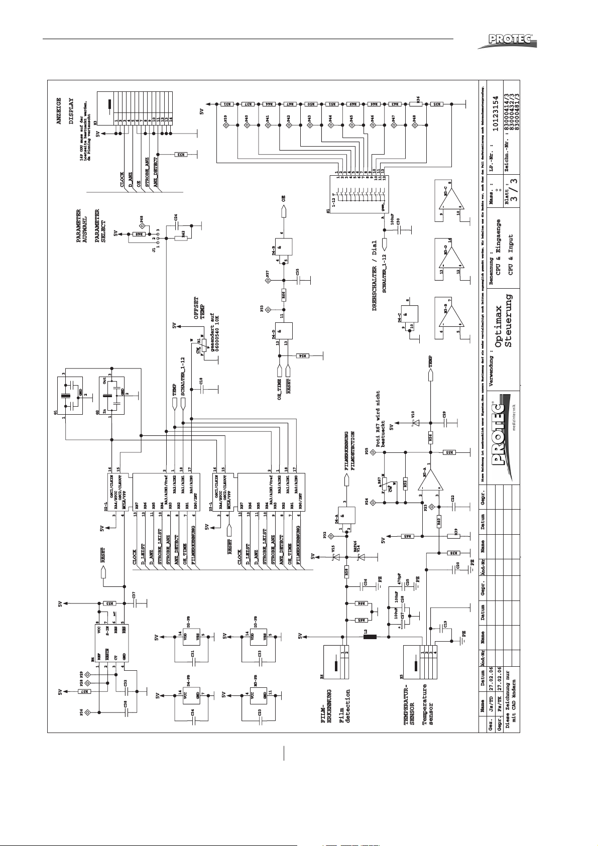
Wiring Charts
®
ANZEIGE
G1
1 3
5V
5V
DISPLAY
14P ODU muss auf der
Loetseite bestueckt werden,
da Pinning vertauscht
PARAMETER
AUSWAHL
GND
2
P29P28
R57
P36
X3
5V
PARAMETER
SELECT
31
OutIn
G2
16
OSC1/CLKIN
D2-L
5V
RESET
R53
876
VCC
S-IN
RESIN
REF
N4
CLOCK
5V
GND
15
OSC2/CLKOUT
MCLR/VPP
RA4/RTCC
4
3
nc7
54
RES
RES
GND
CT
321
C32C38
D_ANZ
2
OE
RB7
13
CLOCK
C37
P68
R48
STROBE_ANZ
ANZ_DETECT
3
2
1
J1
RB6
RB5
11
12
D_LEIST
D_ANZ
5V
5V
141312111098765432L21
R32
C24
R42
5V
TEMP
SCHALTER_1-12
2118&17
RA2/AIN2
RA1/AIN1
RA3/AIN3/Vref
RB4
RB3
RB2
RB1
9&10
STROBE_LEIST
STROBE_ANZ
OE_TIME
ANZ_DETECT
14
VDD
14
VCC
5V
OFFSET
TEMP
NF
W
R1
geaendert auf
cw
C18
RA0/AIN0
RB0/INT
D3-L
678
5V
FILMERKENNUNG
D2-PB
5
VSS
C31
D4-PB
7
GND
C34
P39
06000540 10K
16
15
OSC1/CLKIN
OSC2/CLKOUT
RA4/RTCC
4
3
5V
5V
R31
MCLR/VPP
RESET
P40
RB7
13
CLOCK
R37
RB6
RB5
11
12
D_LEIST
D_ANZ
D3-PB
14
VDD
N3-PB
4
VCC
R44
P41
6
&
D4-B
4
P37
P33
11
D4-D
12
OE_TIME
2118
RA2/AIN2
RA3/AIN3/Vref
RB4
RB3
STROBE_LEIST
STROBE_ANZ
ANZ_DETECT
5
VSS
C33
11
GND
C23
R47
P42
5
C35
R66
13
RESET
17
RA1/AIN1
RA0/AIN0
RB2
RB1
678910
OE_TIME
FILMERKENNUNG
R54
RB0/INT
5V
R50
P43
5V
R51
P44
1
143
1-12
S1
D4-A
P32
V15
X6
FILM-
ERKENNUNG
R49
P45
6
543
2
2
56789
FILMDETECTION
FILMERKENNUNG
3
2
1
V14
BAT46
R58
2
1
Film
detection
P46
9
8OE7
P25
P24
C36
R64
R65
R46
P47
12
11
10
101112
gem.
A
100nF
SCHALTER_1-12
DREHSCHALTER / Dial
5V
Poti R67 wird nicht
bestueckt
N
R67
cw
F
5V
PE
R43
P48
C30
8
&
D4-C
10
9
V10
W
R52
R45
470pF
C25
C28C27
100nF
100uF
+
X5
TEMPERATUR-
SENSOR
R35
R36
-
9
-
13
-
6
TEMP
R56
1
N3-A
+
-
2
3
P23
R40
PE
432
1
Temperature
sensor
83000481/3
83000432/3
83000414/3
10123154
LP.-Nr. :
Zeichn.-Nr. :
N3-C
N3-D
N3-B
8
+
10
14
+
12
7
+
5
/
:
33
Mass. :
Blatt :
CPU & Eingaenge
CPU & Input
Optimax
Steuerung
Controller
Verwendung : Benennung :
C29
R55
Diese Zeichnung ist ausdruecklich unser Eigentum.Ohne unsere Zustimmung darf sie weder vervielfaeltigt noch Dritten zugaenglich gemacht werden. Wir behalten uns die Rechte vor, auch fuer den Fall derPatentierung nach Gebrauchsmusterpruefung.
C22
R39
R38
Name Datum Gepr.
..
PE
C20
And-Nr
..
C19
PE
..
And-Nr Name Datum Gepr.
..
Datum
..
Fs/TK 27.02.06
Js/TD 27.02.06
Name
Gez.
Gepr.
Diese Zeichnung nur
mit CAD andern
40 OPTIMAX
®
 Loading...