

Page 1
Protec Fire Detection plc, Protec House, Churchill Way, Nelson, Lancashire, BB9 6RT, ENGLAND
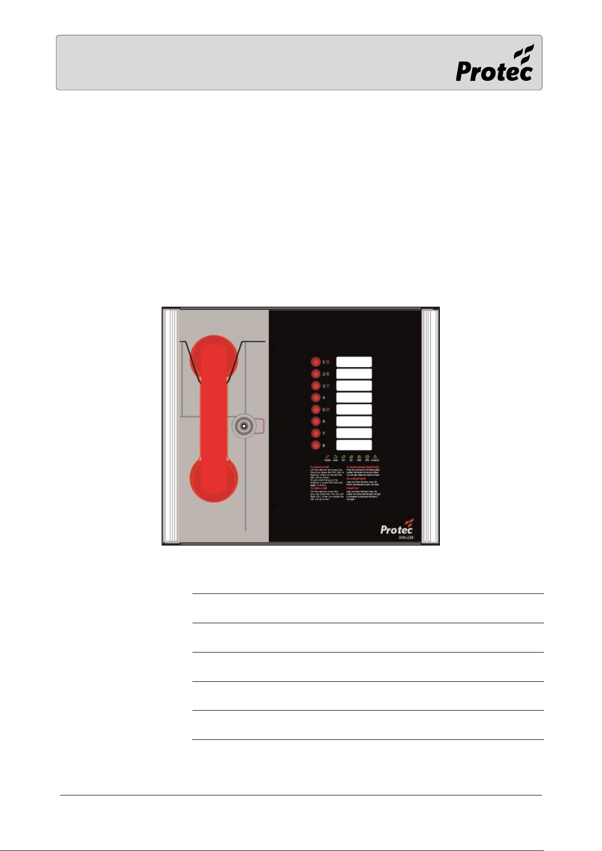
EVX-228 EVCS Master Station
USER MANUAL, CERTIFICATES AND LOG
BOOK
Site Name
Address
Contractor
Commissioned
Page 2

RDM0021/0 Page 2 of 16 © 2017 Protec Fire Detection plc
TABLE OF CONTENTS
1.0 INTRODUCTION .................................................................................................................................3
1.1 What is an Emergency Voice Communication System ..................................................................... 3
1.2 Suitability ................................................................................................................................................. 3
2.0 PRODUCT OVERVIEW .........................................................................................................................3
3.0 IMPORTANT SAFETY INFORMATION................................................................................................4
3.1 Battery Information ............................................................................................................................... 5
4.0 OPERATION ........................................................................................................................................6
4.1 Receiving a call ....................................................................................................................................... 6
4.2 Making a call ........................................................................................................................................... 6
4.3 Ending a call ............................................................................................................................................ 6
4.4 Putting a call on hold ............................................................................................................................. 6
4.5 Conference Call ...................................................................................................................................... 6
4.6 Acknowledging “Assist Call” alarms ..................................................................................................... 6
4.7 Accepting Faults ..................................................................................................................................... 7
4.8 Panel Indicator Test ............................................................................................................................... 7
5.0 INDICATIONS AND CONTROLS .........................................................................................................8
5.1 Mode Indicator Summary ..................................................................................................................... 8
5.2 Power supply and CPU indicator Summary ....................................................................................... 8
5.3 User Indicator Summary ....................................................................................................................... 9
5.4 Zone indicator summary ....................................................................................................................... 9
6.0 MAINTENANCE................................................................................................................................. 10
7.0 CERTIFICATE ..................................................................................................................................... 11
8.0 SITE SPECIFIC INFORMATION: ........................................................................................................ 12
9.0 TECHNICAL SPECIFICATION ............................................................................................................ 15
Page 3

RDM0021/0 Page 3 of 16 © 2017 Protec Fire Detection plc
1.0 Introduction
1.1 What is an Emergency Voice Communication System
An Emergency Voice Communication System, or EVCS, is a system that allows voice communication in
either direction between a central control point and a number of other points throughout a building
or building complex, particularly in a fire emergency situation. The control points, or outstations by
which they are more commonly referred, generally comprise of a Type A outstation, a Type B
outstation, or a Type C Combined Type outstation. “Assist Call” emergency assistance alarm systems
can also be incorporated into the EVCS.
EVCS is generally required in the following situations:
• In any building or sports or similar venue where there are disabled people, or people who may
have difficulty negotiating the evacuation route.
• In buildings with phased evacuation and/or firefighting lifts where it facilitates secure
communications for building managers, fire wardens, and attending fire officers.
• At sports venues and similar complexes, where it will assist stewards in controlling the
evacuation of the area in an emergency.
The EVX-228 Emergency Voice Communications System (EVCS) is designed to fully comply with BS5839
Part 9:2011 for use as a Fire Telephone system, Disabled Refuge Call system or as a combined system
when both Fire Telephones and Disabled Refuge Points are required.
1.2 Suitability
Fire telephone systems are recommended for all public buildings and multi-story buildings over four
floors by BS9999.
Disabled Refuge systems are required in buildings where the public or disabled staff gains access to
any floor other than the ground floor using lifts. Refuge areas are provided at each storey exit from
each protected stairway.
2.0 Product Overview
The EVX EVCS, or EVX-228, comprises of a Master Station and one or more outstations. Additionally
the “Assist Call” emergency assistance alarm system can either be connected to the same line as an
outstation, or connected to a dedicated line. As each line is powered from the Master Station, the
outstations and the “Assist Call” emergency alarm system do not require a separate power supply unit.
This has the additional benefit of each line being fully monitored and battery backed up.
Each EVX-228 Master Station can also perform as a EVX-228 Repeater Station. A EVX-228 Repeater
Station mimics the EVX-228 Master Station both in operation and indication. Any reference in this
document to the EVX-228 Master Station also applies to the EVX-228 Repeater Station, unless specified
otherwise.
The EVX-228 Master Station has been designed for radial star topology. In most cases this will reduce
the cable requirements for all ring-based systems. The topology consists of spurs formed of 1 off two
core 1.5mm CSA cables (soft skin enhanced up to 500m per leg, MICC 200m per leg) to each
outstation.
Page 4

RDM0021/0 Page 4 of 16 © 2017 Protec Fire Detection plc
3.0 Important Safety Information
This Equipment must only be installed and maintained by a suitably skilled and competent person.
This Equipment is defined as Class 1 in EN60065 (Low Voltage Directive) and must be EARTHED.
Caution
Indoor Use Only
Warning
Shock HazardIsolate Before Opening
Warning
TO REDUCE THE RISK OF FIRE OR
ELECTRIC SHOCK, DO NOT EXPOSE THIS
UNIT TO RAIN OR MOISTURE
Warning
THIS UNIT MUST BE EARTHED
Warning
NO USER SERVICEABLE PARTS
Each EVX-228 Master/Repeater Station requires a 3A spur, returning to a breaker clearly marked “EVCS
DO NOT TURN OFF”.
If the EVX-228 Master Station and the EVX-228 Repeater Station are distributed around a site, it is
essential that both EVX-228 Stations are on the same mains phase, as they are classified TEN 230V.
Powering from different phases can mean a 440V potential can be present in a EVX-228 Station during
a major fault incident.
Anti-static handling guidelines
Make sure that electrostatic handling precautions are taken immediately before handling PCBs and
other static sensitive components.
Before handling any static-sensitive items, operators should get rid of any electrostatic charge by
touching a sound safety earth. Always handle PCBs by their sides and avoid touching any
components.
Page 5
RDM0021/0 Page 5 of 16 © 2017 Protec Fire Detection plc
3.1 Battery Information
In the event of mains failure BS5839 Part 9:2011 requires battery backup for 24 hours standby and 3
hours operation thereafter.
A EVX-228 Master/Repeater Station requires one number 12V 7AH vent regulated sealed lead acid
battery. The battery is not supplied with the EVX-228 Master/Repeater Station.
Safety Information:
Sealed Lead Acid batteries contain sulphuric acid which can cause burns if exposed to
the skin. The low internal resistance of these batteries means large currents will flow
if they are accidentally short circuited causing burns and a risk of fire.
Exercise caution when handling batteries.
Power Up Procedure:
Always apply mains power before connecting batteries. When connecting batteries,
always connect the Positive (Red +) terminal first.
Power Down Procedure
Disconnect the batteries before removing the mains power. When disconnecting
batteries, always remove the Negative (Black –) terminal first.
Page 6

RDM0021/0 Page 6 of 16 © 2017 Protec Fire Detection plc
4.0 Operation
All conversations are under the command of the EVX-228 Master Station.
4.1 Receiving a call
One of the eight zone LEDs and the mode LED will flash red to indicate an incoming call. The flash rate
will identify the outstation type, with a Type A outstation having a faster flash rate than a Type B
outstation.
Lift the Master handset receiver. The User LED will illuminate Red.
Press the corresponding zone button (indicated by the red flashing LED). This LED and the User LED
will change to flashing green to show that this line is now connected, and a conversation can take
place.
4.2 Making a call
To make a call, lift the Master handset receiver and the User LED will illuminate red.
Press the zone button for the required outstation. The corresponding zone LED will flash red. This
flash rate will be slower than the flash rate for either an incoming Type A or Type B call.
When the outstation answers the call, the zone LED flashes green, the mode LED illuminates red and
the user flashes green to indicate this line is now connected and a conversation can take place.
4.3 Ending a call
To end the call from the outstation, either replace the Type A receiver back on its hook, or press the
call/cancel button for a Type B outstation.
To end a conversation from the EVX-228 Master Station, replace the Master handset receiver back on
its hook. Note: This will not end the call, only the conversation. The outstation will revert back to
requesting a call, and the zone LED will flash red to indicate this. The call MUST be ended at the
outstation.
4.4 Putting a call on hold
To put a call on hold, press the zone button for the required outstation that is already connected. The
zone LED will change from flashing green to flashing green/red. The hold tone will be heard in the
handset.
To reconnect the call, press the zone button for the required outstation again. The zone LED will
change from flashing green/red to flashing green to indicate the call is now connected again.
4.5 Conference Call
Depending upon the number of Line Cards fitted in the EVX-228 Master Station, up to eight lines can
be connected to the conference call. See 4.1 for receiving a call, and 4.2 for making a call to each
individual outstation. The EVX-228 Master Station controls which lines are involved in the conference,
and only one conference group is allowed.
4.6 Acknowledging “Assist Call” alarms
When an “Assist Call” goes into alarm, the appropriate zone LED will flash blue, and a two-tone buzzer
sounds to indicate that an “Assist Call” alarm has been operated.
To acknowledge the alarm, press the corresponding zone button, and the blue LED will illuminate
continuously with an intermittent buzzer tone every 15 seconds. If after 2 minutes the “Assist Call”
alarm has not been cancelled, the buzzer will resound and the LED will flash blue.
Page 7

RDM0021/0 Page 7 of 16 © 2017 Protec Fire Detection plc
4.7 Accepting Faults
Before accepting faults, the fault must be noted in the log book, along with the time the fault was
reported.
To accept the fault, enter either the access level 2 (code: 1664) or access level 3 (code: 1812) menu,
then press zone button 1. The buzzer will silence and the general fault LED will now go steady.
Press zone button 8 to exit this menu and to return to the menu options.
The buzzer will resound on each new fault.
4.8 Panel Indicator Test
To test the panel indicators, enter either the access level 2 (code: 1664) or access level 3 (code: 1812)
menu, then press zone button 2.
All LEDs will illuminate in a predefined sequence, and the buzzer will sound.
Press zone button 8 to stop the panel indicator test and to return to the menu options.
Page 8
RDM0021/0 Page 8 of 16 © 2017 Protec Fire Detection plc
5.0 Indications and Controls
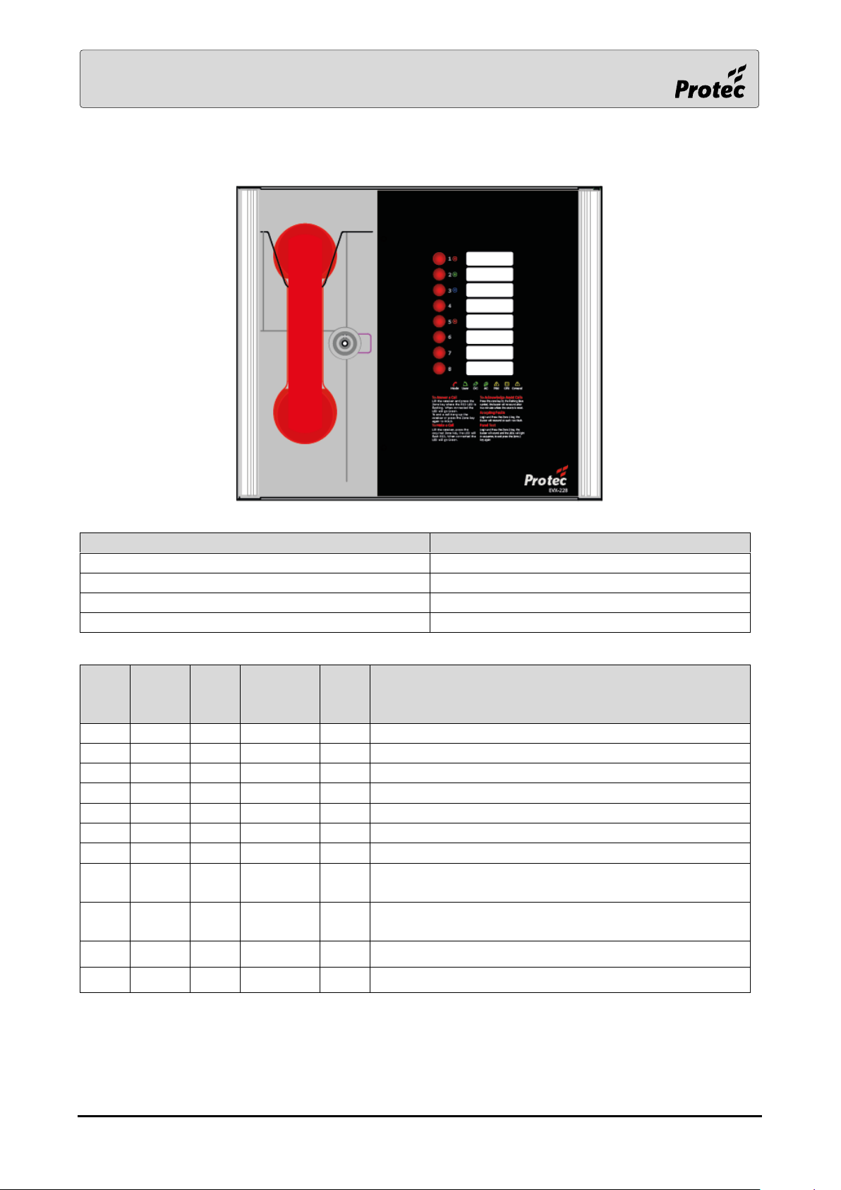
5.1 Mode Indicator Summary
Mode
Description
Green solid
Normal state
Red solid
Outstation off hook
Blue solid
Assist call active
Yellow Solid
Panel Disabled
5.2 Power supply and CPU indicator Summary
AC
DC
PSU
General
CPU
Description
✓
Mains OK
x Flash
Flash
Mains failure
✓
Battery OK
x Flash
Flash
Battery open circuit
x ✓ Flash
Battery short circuit
Flash
✓
Flash
Battery high impedance
✓ Flash
✓
PSU processor fail
Flash
✓
Display or Exchange Processor Fault or DisplayExchange comms flt
Flash
Display or Exchange Processor Fault or DisplayExchange comms flt on remote panel (if applicable)
Flash
Flash
Remote Battery fault
Flash
Flash
Remote Mains fault
✓ = LED illuminated
x = LED off
Flash= LED Flashing
Note: When faults are accepted the general LED illuminates solid.
Page 9

RDM0021/0 Page 9 of 16 © 2017 Protec Fire Detection plc
5.3 User Indicator Summary
Red
Master handset off hook
Flashing Yellow
Master handset open circuit
Cyan
User logged in
Magenta
Engineer logged in
Flashing green
Call connected
Flashing Red/Green
Call on hold
Solid Yellow
Master handset short circuit
Solid White
Call connected on remote master station
5.4 Zone indicator summary
Zone Indicator
Status
User Indicator
Status
Buzzer
Status
Description
Slow flash red
Off
Outgoing call
Fast flash red
Ringing
Incoming call from type A
outstation
Normal flash red
Ringing
Incoming call from type B
outstation
Normal flash green
Normal flash green
Off
Call connected to local master
handset
Normal flash
green/red
Normal flash
green/red
Off
Call on hold
Normal flash
green/white
Solid White
Off
Call connected via a remote master
handset
Solid yellow
On
Line Short circuited
Slow flash yellow
On
Line card missing
Normal flash yellow
On
Line Open circuit or EOL missing
Fast flash yellow
On
Line Earth fault
Solid cyan
Solid cyan
Off
Access level 2
Solid magenta
Solid magenta
Off
Access level 3
Normal flash blue
2 Tone Alarm
Incoming Assist Call alarm
Solid blue
Intermittent
double Beep
Assist call acknowledged
Page 10

RDM0021/0 Page 10 of 16 © 2017 Protec Fire Detection plc
6.0 Maintenance
It is a requirement of BS 5839-9:2011 that a maintenance agreement be in place for the EVCS. The
maintenance schedule should be as follows:
Frequency
Test
Weekly
Test a different outstation on the system each week and make a call to the control.
Repeat each week until all outstations and master stations are tested. Record these
results in the site log. *if more than one master station is present alternate weekly.
Biannually
Engineer call to check system operation, intelligibility, field strength of attached AFILS
equipment and check battery health. Record results and any variations into the site
Log Book
Yearly
Engineer call to check system operation perform 100% outstation and master station
operation, field strength of attached AFILS equipment and check battery health.
Record results and any variations into the site Log Book
5 Yearly
In addition to Yearly tests replace all batteries and record in Log Book.
Page 11

RDM0021/0 Page 11 of 16 © 2017 Protec Fire Detection plc
7.0 Certificate
Combined Certificate for Design Installation and Commissioning for an
Emergency Voice Communication System (EVCS) to BS5839 part 9 (2011)
Site Name
Address
Customer
Address
Areas Covered
System Design:
In accordance with section 1 of BS 5839 : Part 9 : 2011 sub clause 6 the system design is has in
accordance with the recommendations of this code except for the following:
Installation:
In accordance with section 3 of BS 5839 : Part 9 : 2011, the wiring has been inspected and tested
and been found to be in accordance with the recommendations of this code except for the
following:
Commissioning:
In accordance with Section 4 of BS 5839 : Part 9 : 2011: sub clause 22C)
1. Intelligible conversation is heard at all locations.
2. All controls and indicators operate correctly
Acceptance:
The system is accepted in good working order and, in accordance with BS5839: Part 9, 2011, record
drawings, operating instructions and a system log book have been supplied and received.
Attention has been drawn to the recommendations concerning user's responsibilities, particularly
those concerned with routine attention and test procedures in section 5, and an appointed
responsible person should be nominated by the customer in accordance with the recommendations
of Section 6 of BS5839 : Part 9 : 2011.
Engineer
Date
Position
Signature
Page 12

RDM0021/0 Page 12 of 16 © 2017 Protec Fire Detection plc
8.0 Site Specific Information:
Responsible Person
Date
Position
Signature:
Equipment Locations
EVX228 Location ______________________________________________________________________________________
Cable ID
Line
Area Served
1 2
3
4
5
6 7
8
Page 13

RDM0021/0 Page 13 of 16 © 2017 Protec Fire Detection plc
Log Book Page 1
Date
Event or Work Done
Engineer
Company
Signature
EVX System commissioned
Page 14

RDM0021/0 Page 14 of 16 © 2017 Protec Fire Detection plc
Log Book Page __
Date
Event or Work Done
Engineer
Company
Signature
Copy this page as many times as required
Page 15

RDM0021/0 Page 15 of 16 © 2017 Protec Fire Detection plc
9.0 Technical Specification
Product Code
EVX-228
Power Supply and Charger
AC Input
230Vac+10%- 20% 50/60Hz
Internal power supply
12Vdc nominal
Supply and battery
Monitored open, Short, Fuses
Protection
Deep discharge, Short, Thermals
Temperature
compensation
Yes
Battery information
Space for Up to 1x 12V 7AH VRSLA
Mains fuse
1A HRC(T)
Battery fuse
Self Resetting PTC
Max charge current
500mA
Inputs
Number of lines
Between 2 and 8
Remote enable
Short to use
End of line monitoring
10KΩ 0.6watt resistor
Relay outputs
Number and type
2: Fault and In use, volt free 30Vdc 1A
Controls
Number and type
8 push button zone keys
Indication
Number and type
8x RGB Line indicators
3x PSU Status Indicators
1 x CPU Fault Indicators
1x General Fault Indicator
1x RGB Mode Indicator
1x User Status Indicator
Enclosure Details
Back box finish
RAL 7035 Grey
Dimensions
350 x 300 x 95
Entries
14 knockouts top, 2x rear slots
Flush Cutout
352 x 302 x 85 deep
Page 16

RDM0021/0 Page 16 of 16 © 2017 Protec Fire Detection plc
This equipment has been manufactured in conformance with the requirements of all
applicable EU council directives and regulations.
Electrical or electronic devices that are no longer serviceable must be collected
separately and Sent for environmentally compatible recycling (in accordance with the
European Waste Electrical and Electronic Equipment Directive). To dispose of old
electrical or electronic devices, you should use the return and collection systems put in
place in the country concerned.
The policy of Protec Fire Detection plc is one of continuous improvement. As such we reserve the right
to make changes to product specifications at any time and without prior notice. Errors and omissions
excepted.
 Loading...