

Page 1
Protec Fire Detection PLC, Protec House, Churchill Way, Nelson, Lancashire, BB9 6RT.
Telephone: +44 (0) 1282 717171
Fax: +44 (0) 1282 717273
Web: www.protec.co.uk
Email: [email protected]
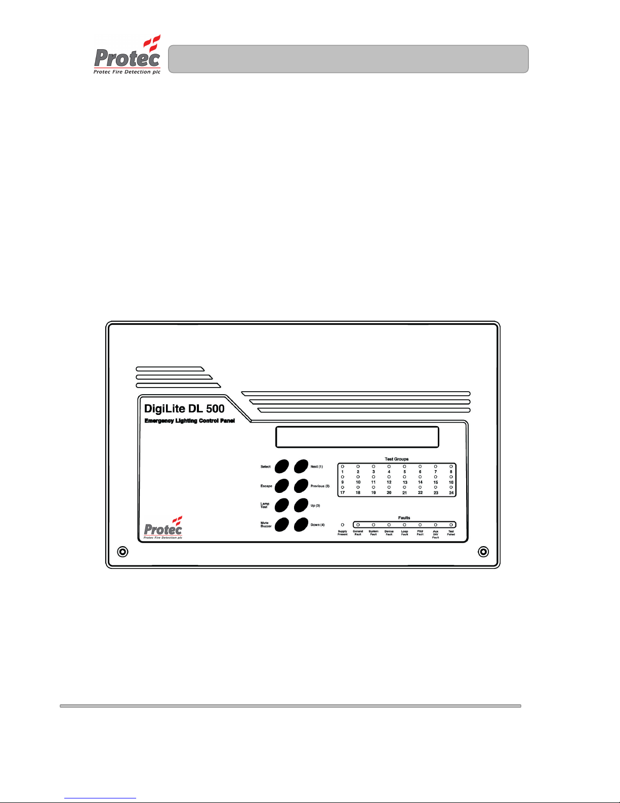
Digilite® Emergency Lighting
Control Panel
INSTALLATION MANUAL
Page 2

2
N93-561-85 Issue 0 © Copyright Protec Fire Detection plc 2009
Document Revision Details
Issue
Modification Detail
Author
Date
0 Document Creation NH 02/09
Page 3

3
N93-561-85 Issue 0 © Copyright Protec Fire Detection plc 2009
Table of Contents
1.0 IMPORTANT NOTES – PLEASE READ ........................................................................4
2.0 ITEMS SUPPLIED WITH THE DIGILITE® PANEL ........................................................4
3.0 INTRODUCTION .............................................................................................................4
4.0 CABLING REQUIREMENTS ..........................................................................................5
4.1 General .....................................................................................................................5
4.2 Mains Wiring .............................................................................................................5
4.3 Auxiliary Wiring .........................................................................................................5
4.4 Loop Wiring ..............................................................................................................5
5.0 INSULATION TESTING OF CABLING PRIOR TO CONNECTION ...............................8
6.0 INSTALLATION PROCEDURE ......................................................................................8
7.0 COMMISSIONING ........................................................................................................ 11
7.1 Connecting the Loop ............................................................................................. 11
7.2 Connecting the Mains ............................................................................................ 11
7.3 Installing and Connecting The Standby Batteries ................................................. 12
7.4 Switching On ......................................................................................................... 12
8.0 DIGILITE® TECHNICAL SPECIFICATION ................................................................. 13
9.0 APPENDIX 1 DIGILITE® SPARES LIST ..................................................................... 14
10.0 APPENDIX 2 DIGILITE® MAIN PCB DETAILS .......................................................... 15
Page 4

4
N93-561-85 Issue 0 © Copyright Protec Fire Detection plc 2009
1.0 Important Notes – PLEASE READ
• THE DIGILITE® PANEL AND ITS ASSOCIATED CONNECTIONS MUST BE INSTALLED,
COMMISSIONED AND MAINTAINED BY A SUITABLY SKILLED AND COMPETENT PERSON.
• THIS EQUIPMENT MUST BE EARTHED.
• THIS EQUIPMENT IS NOT GUARANTEED UNLESS INSTALLED AND COMMISSIONED IN
ACCORDANCE WITH CURRENT NATIONAL STANDARDS.
• THIS EQUIPMENT HAS BEEN DESIGNED AND MANUFACTURED TO CONFORM WITH
THE REQUIREMENTS OF ALL APPLICABLE EU COUNCIL DIRECTIVES.
• THIS MANUAL MUST BE THOROUGHLY READ AND UNDERSTOOD BEFORE
INSTALLATION AND COMMISSIONING OF THIS EQUIPMENT IS UNDERTAKEN.
• MAY CONTAIN TRANSMITTER MODULE FCC ID: ED9LMX9838.
• Digilite® IS A REGISTERED TRADEMARK OF PROTEC FIRE DETECTION PLC.
2.0 Items Supplied with the Digilite® panel
• Installation manual.
• Commissioning manual.
• User manual.
• Mounting template.
3.0 Introduction
The Digilite® control panel has been designed to automatically test emergency lighting fittings and
report any faults detected.
To facilitate testing the fittings may be programmed into groups (up to a maximum of 24). Each group
is tested on the corresponding day of each month, with the functional test being replaced by a full test
once every year.
Digilite® fittings generally incorporate an LED which readily displays the current status of the fitting.
Green is normal, Flashing green indicates the fitting is being tested, flashing amber indicates the unit
has a fault or has failed a test.
The panel logs all test results, which may be viewed or cleared at any time on the panel.
Test results, faults and panel status/configuration may be printed out by using the standard
Bluetooth® printer, or from a PC by specifying the optional TCP/IP network interface (assuming
relevant PC software has been set-up). The correct model of panel must be specified when ordering.
The TCP/IP interface may be used to network up to 32 panels, which may then be operated remotely
via a PC which instigates/aborts tests and logs panel events.
Page 5
5
N93-561-85 Issue 0 © Copyright Protec Fire Detection plc 2009
4.0 Cabling Requirements
4.1 General
All wiring associated with the system must conform to the current I.E.E Regulations and cabling must
conform to the relevant BS specifications. ECA recommended Cable Separation for Electromagnetic
Compatibility in Buildings must be followed.
4.2 Mains Wiring
The Digilite® panel requires a mains supply exclusive to the panel that uses fixed three core wiring
(between 0.75mm2 and 2.5mm2) which is fed from a double pole isolating fused spur, fused at 3A.
Unauthorised operation of the mains supply should not be allowed and the fused spur should be
labelled “EMERGENCY LIGHTING PANEL: DO NOT SWITCH OFF”
4.3 Auxiliary Wiring
Any auxiliary wiring (keyswitch, global contacts etc) should be wired in screened cable, with the
screen securely connected to the earthing point supplied in the panel.
The TCP/IP interface (if fitted) has a socket which accepts standard RJ45 type network cabling
connectors. The CAT5 network cable (supplied by the sites relevant IT department) should be plugged
into here.
4.4 Loop Wiring
The Digilite® loop wiring carries both power and data to the Digilite® fittings. In order for the system to
operate correctly the voltage drop along the loop must be kept within certain limits.
The loop wiring must be wired from the panel terminal marked ‘LOOP1 A’ round all the fittings and
reconnected at the panel terminal marked ‘LOOP1 B’.
Spurs off the loop are permitted, assuming that they meet the required resistance criterion.
Table 4.0 shows the general characteristics required for the loop cabling.
Table 4.0
Recommended Cable Type Twin core twisted or twin core screened (screen connected to
earth)
Recommended Size 1.0mm2 to 2.5mm2 (Depends on loop volt drop calculations)
Maximum Resistance 40Ω per conductor (cold resistance)
Maximum Capacitance 2µF per km
Maximum Cable distance 2km (Depends on loop volt drop calculations)
The voltage drop on the loop is a function of both the resistance of the loop cabling (determined by the
gauge of cable and the length of the loop) and the current that the loop must carry (determined by the
number of loop devices connected).
Each Digilite® fitting draws an average current of 200µA, but the loop cable must be able to support
the peak loop current of 400µA for data signalling purposes. The voltage drop on the loop must be
limited to 8V in order for the data to be received by the fitting.
Knowing these parameters an equation to determine the maximum loop resistance can be developed.
Page 6
6
N93-561-85 Issue 0 © Copyright Protec Fire Detection plc 2009
In order to select the required gauge of cabling for a given installation, the maximum cold resistance of
the cable must be calculated. Table 4.1 gives guidelines for cable selection, showing cable AWG
versus resistance per km.
Please note that the resistance of the actual cable being used on a particular installation must be used
to determine if the cable is acceptable or not. This data will be available from the cable data sheets,
available from the cable manufacturer.
Table 4.1 – Cable DC resistance guidelines
AWG
DC resistance (Ω per km)
12 5.5
13 7
14 9
15 11
16 14
17 17
18 21
19 27
20 34
Equations have been developed which allow the system designer to calculate a value of cable
resistance for a given installation type.
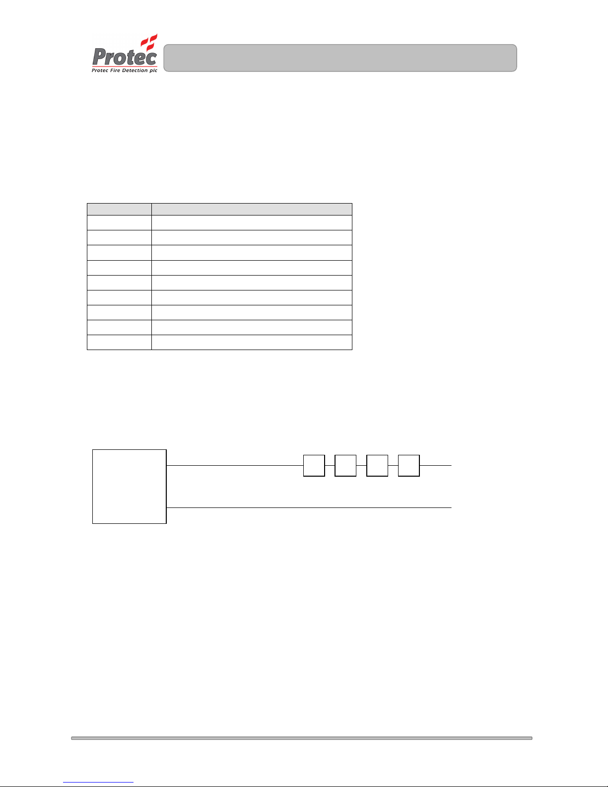
The equations assume worst case conditions where all the fittings are lumped at one end of a broken
loop (effectively a spur).
Equation 1 – Calculating the maximum cable resistance of a spur.
Loop resistance
(max)
= ( 8 / ( η x 0.0004 ) ) Ω (Equation 1)
Where η is the number of Digilite® fittings on the cable.
Worked Example 1
The following example shows a situation where 280 fittings are required on a 1.5km loop.
η = 280.
Loop resistance
(max)
= ( 8 / ( 280 x 0.0004 ) ) = 71Ω
This shows that the loop wiring must have a cold resistance of no more than 71Ω (or 35.5Ω per
conductor). So using table 3.1 20 AWG cable would be sufficient.
Digilite®
control panel
Number of fittings (η)
Loop broken
at one end
Page 7
7
N93-561-85 Issue 0 © Copyright Protec Fire Detection plc 2009
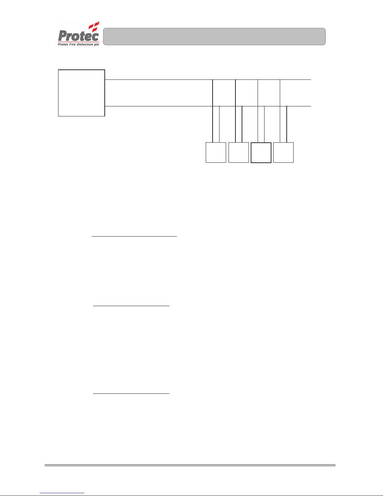
Equation 2 – Calculating the maximum cable resistance of a spur fed off a loop.
Where:
ηtotal is the total number of fittings on the total loop (loop and all spurs)
ηspur is the total number of fittings for a particular spur
Rloop is the go and return resistance of the main loop
Rspur is the go and return cold resistance of a particular spur
To calculate the maximum go and return cold resistance for a particular spur the following equation
may be used.
R
spur (max)
= 8 – ( R
loop
x η
total
x 0.0004 )
( η
spur
x 0.0004 )
Worked Example 2
The following example shows a situation where the main loop resistance is 25Ω and there are four
spurs fed off the loop, each with 70 fittings connected.
The maximum go and return cold resistance for a spur may be calculated as follows.
R
spur (max)
= 8 – ( 25 x 280 x 0.0004 )
( 70 x 0.0004 )
R
spur (max)
= 185 Ω
Worked Example 3
The following example shows a situation where the main loop resistance is 16Ω and there are four
spurs fed off the loop, two with 100 fittings connected and two with 70 fittings connected.
The maximum go and return cold resistance for a spur with 100 fittings may be calculated as follows.
R
spur (max)
= 8 – ( 16 x 340 x 0.0004 )
( 100 x 0.0004 )
R
spur (max)
= 145 Ω
Digilite®
control panel
Loop broken
at one end
ηspur
η
spur
η
spur
η
spur
Rloop (Ω)
Rspur (Ω)
Page 8
8
N93-561-85 Issue 0 © Copyright Protec Fire Detection plc 2009
5.0 Insulation Testing of Cabling Prior to Connection
Before connecting any external cables to any field device or the Digilite®, tests must be carried out
using a 500V DC insulation tester (‘Megger
TM’
). The readings between each cable core, and each core
and earth should be greater than 10MΩ.
Important Notes:
• Digilite® Fittings or the Digilite® panel must NOT be connected when high voltage insulation tests
are being performed on the cabling, the cabling must be completely discharged prior to
connection to any fittings or the Digilite® panel.
• Equipment connected to the cabling during insulation tests could be damaged with the high
voltages used during the test, invalidating any warranty.
6.0 Installation Procedure
The Digilite® panel circuit boards are housed in a plastic enclosure. When the front is removed from
the panel the main circuit board and the batteries are fully accessible. The panel can still be controlled
even though the front has been removed.
The panel may be surface or flush mounted (no extra bezel required).
The panel must be located internally in an area that is not subject to dampness, extremes of
temperature or physical abuse. The environmental limits are given in section 8.0
1) Unpacking
After opening the box remove the installation template from the packaging, leaving the
Digilite® panel in the cardboard box for protection.
2) Preparing the Mounting Position
Use the installation template in conjunction with a spirit level to mark out the fixing locations
for the panel. Drill and plug the mounting holes previously marked.
3) Removal of the Door
Remove the Digilite® panel from the packaging. Remove the two screw covers from the lower
two corners of the front door and unscrew the two front door fixing screws.
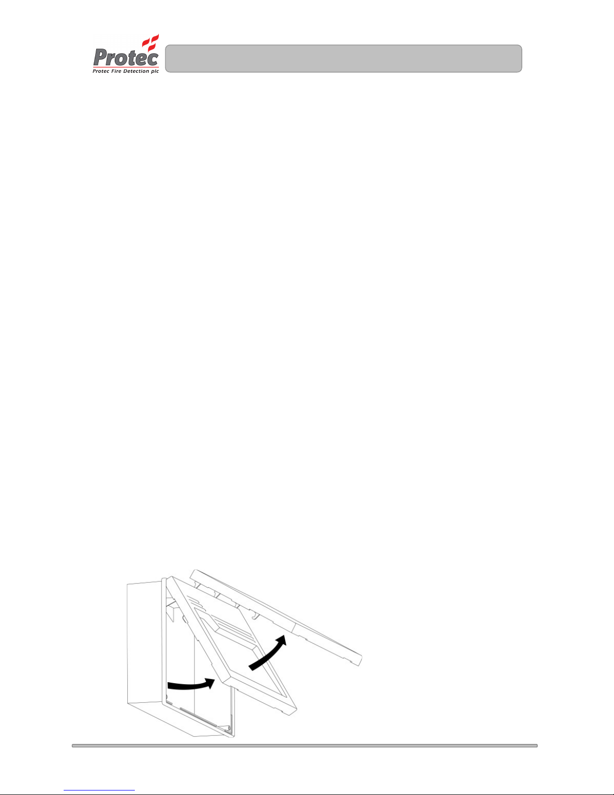
Swing the door upward from the bottom and lift away, see figure 6.0.
Put all removed parts in a safe, dry place.
Figure 6.0 – Removing the door from a Digilite® panel
Page 9
9
N93-561-85 Issue 0 © Copyright Protec Fire Detection plc 2009
4) Removal of the Main PCB.
NOTES ON ANTI-STATIC HANDLING OF THE PCBs
Before handling any of the circuit boards in the Digilite® it is vital that any operatives
discharge themselves of any static charge that may have built up on them. This can be
done by momentarily touching a solid earth point (a non-painted part of a radiator, for
example).
Handle the PCBs by their sides and DO NOT touch the electronic components on them.
The PCB should be stored in a clean, dry place away from the place of work. Retain the
PCBs in a cardboard box for safety until they are required.
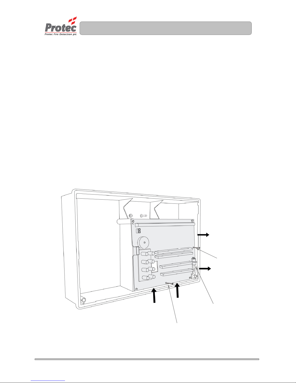
Disconnect the 3 way connector from the main PCB, taking care not to strain the connector or
the PCB. Leave the connector attached to the Power Supply PCB.
Unscrew and remove the two mounting screws on the main PCB. Carefully slide the Main
PCB upward (stage 1) and lift away from the plastic enclosure (stage 2). See figure 6.1. If the
optional TCP/IP or Bluetooth® printer PCB is fitted in the centre channel of the enclosure,
carefully disconnect the wire connected to the rear of the main board
Store all screws and PCBs in a safe, dry place.
Figure 6.1 – Removal of the Digilite® Main PCB.
.
PCB fixing screw
Stage 1
Stage 2
3 way power
connector
PCB fixing screw
Page 10
10
N93-561-85 Issue 0 © Copyright Protec Fire Detection plc 2009
5) Preparing and Fixing the Panel Back-box
The mains cable entry position must be kept away from other system cabling.
Using a screwdriver carefully remove the knock-outs at the required cable entry positions and
mount the enclosure at the position prepared in (2) whilst feeding the cables into the
enclosure.
6) Refitting the Main PCB
Note: Before re-fitting the main PCB the connections to the Power Supply PCB (see
section 7) and TCP/IP interface (if fitted) should be connected.
DO NOT SWITCH MAINS POWER ON AT THIS POINT !
Route the battery cables through to the battery compartment using the channels provided.
If fitted reconnect the wire from the rear of the Digilite® main board to the interface fitted in the
centre channel of the enclosure.
Replace the Main PCB (a reversal of removal), ensuring it is pushed fully down to the bottom
edge of the panel. Secure with the two screws removed previously. Take care not to over
tighten the screws.
Re-connect the three way cable from the Power Supply to the Main PCB, do not use undue
pressure and ensure the cable is clipped into the locking ramp on the PCB header securely.
7) Re-fitting the Door
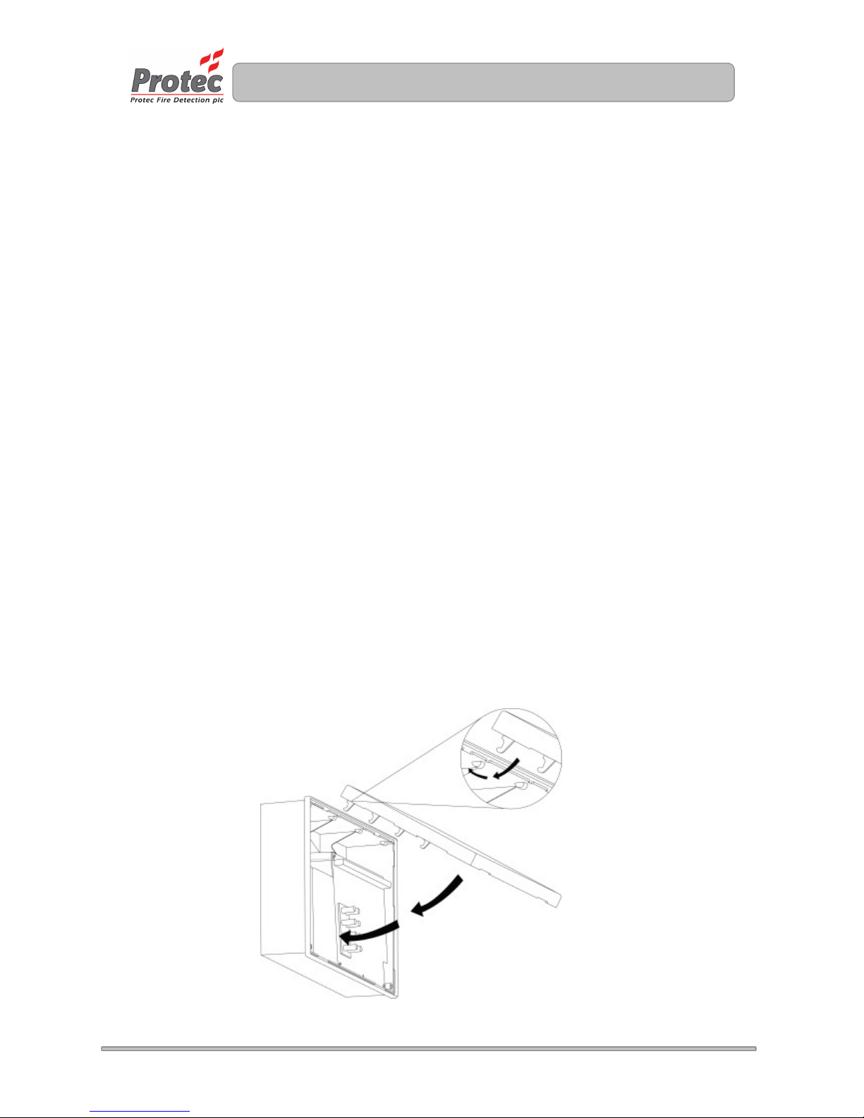
Replace the plastic door by offering the top of the door up to the groove at the top of the
plastic back-box.
Swing the door down and ensure it pushes fully home into the back-box, without fouling the
rubber keypad or light-guides on the main PCB. See figure 6.3 for details.
Tighten the two screws in the lower two corners of the door, and replace the screw covers.
Figure 6.3 – Refitting the Digilite® door.
Page 11
11
N93-561-85 Issue 0 © Copyright Protec Fire Detection plc 2009
7.0 Commissioning
7.1 Connecting the Loop
The Digilite loop wiring must always be connected as a complete loop from the panel to each
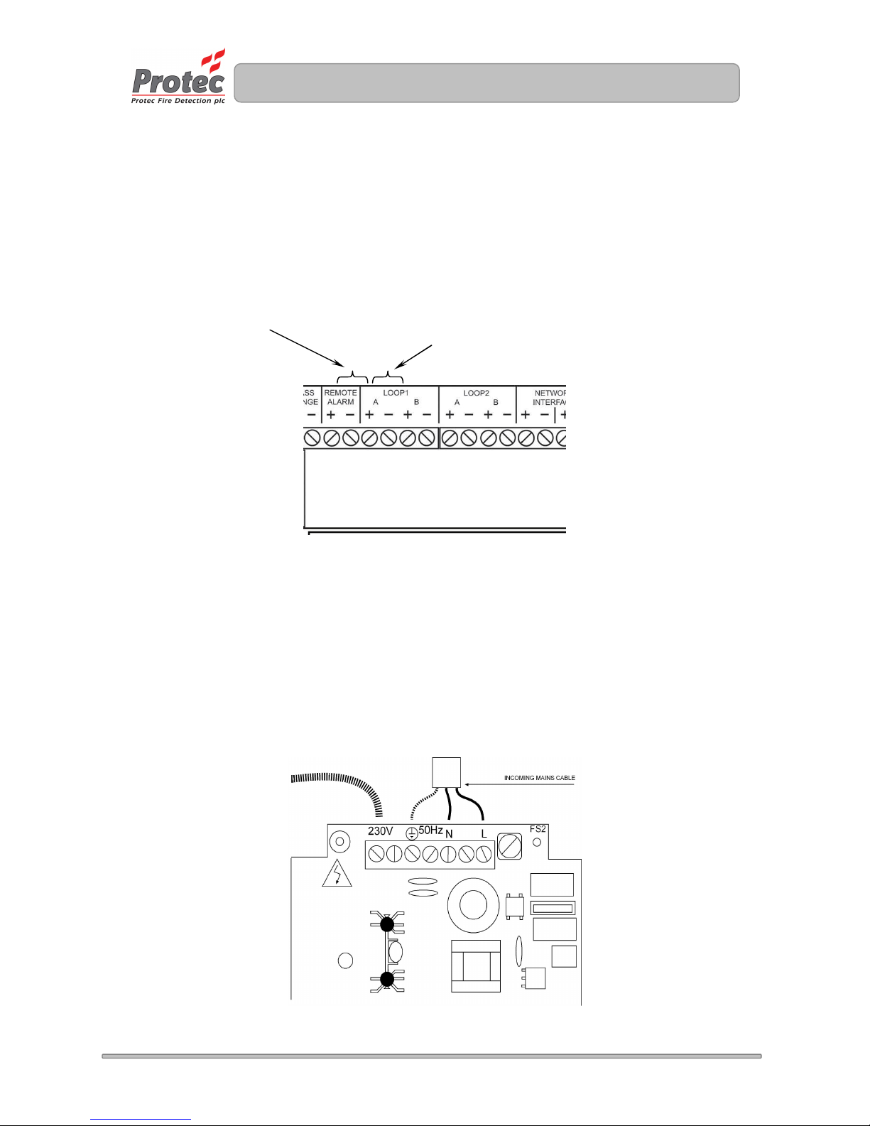
outstation, then back to the panel again. Please see figure 7.0
The loop wiring carries both power and bi-directional signalling to the Digilite outstations.
Figure 7.0 Loop Connection Details
7.2 Connecting the Mains
Important Note:
Pay particular attention that the earth cable is firmly connected to the earth terminal of the
power supply, and that the earth strap from the power supply PCB to the earth post is sound.
Ensure the fused double pole isolator is in the ‘OFF’ position then connect the incoming mains cable
to the appropriate terminals on the power supply PCB (see figure 7.1).
Figure 7.1 Power Supply Terminal Details
Outgoing loop connections
Return loop connections
Page 12
12
N93-561-85 Issue 0 © Copyright Protec Fire Detection plc 2009
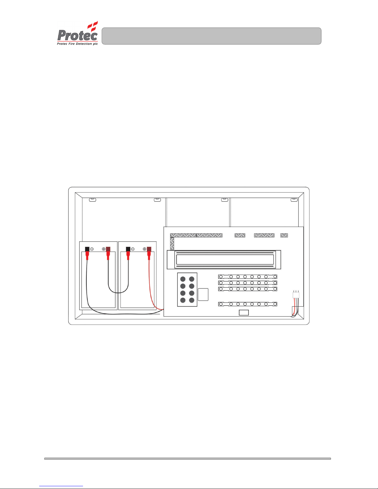
7.3 Installing and Connecting The Standby Batteries
The panel is designed to house two 12V 3.3Ah Valve Regulated Sealed Lead Acid (SLA) batteries.
These fit into the left hand compartment of the Digilite® and should be secured with the Tie-wraps
provided.
The two batteries must be connected in series, a connecting link is supplied for this purpose.
The batteries must then be connected to the power supply PCB using the wires provided, please
observe polarity when connecting.
Ensure all spade connectors are pushed fully home onto the battery terminals.
Figure 7.2 shows the location and connection details for the batteries.
Figure 7.2 Installation of Digilite® Standby batteries (shown with the lid removed)
7.4 Switching On
Switch the fused isolator to the ‘ON’ position. The ‘Supply Present’ indicator should illuminate on the
front of the panel and, assuming all other connections are correct the Digilite® should be displaying
the ‘System Healthy’ screen on the LCD.
The Digilite® is now ready to be commissioned and programmed.
Page 13

13
N93-561-85 Issue 0 © Copyright Protec Fire Detection plc 2009
8.0 Digilite® Technical Specification
Power Supply Mains 230V AC. Nominal (+/-10%)
Integral Charger 1A switch mode, temperature compensated, 250mA battery charge current.
Batteries monitored for disconnection, failure and deep discharge
Auxiliary 24V output 24V DC, 100mA max, monitored for fuse failure. (fuse self resetting)
Maximum Battery Size 2 x 12V 3.3Ah
Mains Fuse 1A HRC ceramic 20mm
Battery Fuse 1.6A F 20mm
Working Voltage 20V to 30V DC
Current Consumption 15mA (24V DC. Supply, not in alarm, mains failed, buzzer slow beeping,
General and PSU fault light illuminated) + loop load
Temperature Range 0 to 40 degrees C
Humidity Limit 85% Non-Condensing
Environment Meets IP30 if mounted in a dry position that does not exceed the temperature
and humidity limits given
Mounting 3 or 4 points surface mount
Page 14

14
N93-561-85 Issue 0 © Copyright Protec Fire Detection plc 2009
9.0 Appendix 1 Digilite® Spares List
Description Protec Stock Code
1.6A F battery fuse NK15-055-40
1A HRC mains fuse NK15-131-35
Red battery lead N41-791-64
Black battery lead N41-790-63
Battery inter-connection lead N41-796-44
Full spares kit N62-589-78
User Manual N93-560-84
Installation manual N93-561-85
Page 15
15
N93-561-85 Issue 0 © Copyright Protec Fire Detection plc 2009
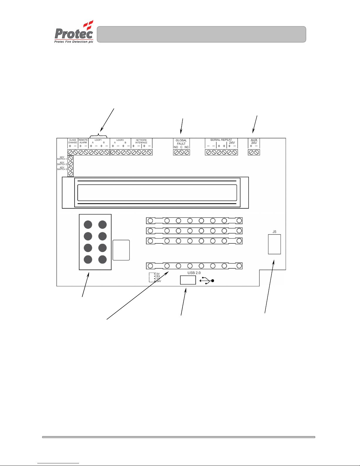
10.0 Appendix 2 Digilite® Main PCB Details
The diagram below shows the Digilite® control PCB and highlights the main connections and controls.
Connection to loop devices
Global fault contacts
Auxiliary 24V output
Keypad
USB PC connection
Connection to 24V
Power Supply Unit
LED showing current
group(s) in test
 Loading...